Evaluation of new GFRTP and CFRTP using epsilon caprolactam as matrix fabricated with VaRTM
-
 ,
,

Abstract
Thermoplastic resins used as a matrix of fiber reinforced thermoplastics (FRTPs) are composed of high polymers that remain highly viscous even at a higher temperature than their melting points. As a result, they need an even higher temperature, a higher pressure and a longer processing time to allow them to bond with fibers that require large and specialized equipment. In contrast, fiber-reinforced thermoset plastics (FRPs) can be easily molded owing to the use of lower viscosity liquid resin as the matrix using simpler devices. In this paper, a new fabrication method of FRTPs using in situ polymerizable ε caprolactam as the matrix is presented. This method uses vacuum-assisted resin transfer molding without the need for large and specialized equipment. The ε-caprolactam molecules were converted from their monomer form into a polyamide 6 resin, with ring-opening polymerization of ε-caprolactam during the molding process at a lower temperature than its melting temperature. The two kinds of FRTPs obtained using ε-caprolactam as the matrix had neither voids nor unfilled parts because ε-caprolactam had a very low viscosity before the polymerization. These FRTPs not only exhibit superior bending properties but also are suitable for high-speed molding, namely, within a few minutes of process time.
1 Introduction
Fiber-reinforced plastics (FRPs) have been widely used as a higher specific strength material in place of metallic materials. As thermosetting resin, a type of FRP matrix, changes into a permanent cross-link polymeric structure while it hardens, it cannot be remelted even by heating and thus it is difficult to recycle or reuse. In contrast, fiber-reinforced thermoplastics (FRTPs) use non cross-linked, straight-chain polymers as a matrix so that remelting and remolding are possible by heating. This means that they can be easily recycled and reused. Since materials that reduce environmental burdens have been explored for possible applications to automobiles, FRTPs as automobile structural parts are more favorable than metallic materials with respect to the specific strength and rigidity. In order to obtain a higher strength of FRTPs, they must be developed by using continuous fibers, which will increase their contents. However, it is not easy to fabricate such FRTPs.
Thermoplastic resins as the matrix for FRTPs are naturally in a solid state and are composed of high polymers that remain highly viscous even at a higher temperature than their melting points. Since they need a higher temperature, a higher pressure and a longer processing time to allow them to bond with fibers, FRTPs with pellets including short fibers [1–3] have been fabricated with a method of injection molding. In the case of long-fiber FRTPs, hot-press molding combined with thermoplastic films [4] has been used and this method requires a higher temperature and pressure, and a longer cooling process in order to prevent the distortion of FRTPs. Unlike FRPs, this method is not easily molded owing to the use of lower viscosity liquid resin as the matrix.
Other methods of fabricating FRTPs containing high volume fractions of continuous fibers have been studied by using a cyclic oligomer [5, 6] and in situ polymerizable epsilon-caprolactam (ε-caprolactam) as the matrix. This ε-caprolactam molecules were converted from their monomer form into a polyamide 6 (PA6) resin, with ring-opening polymerization of ε-caprolactam during the molding process at a lower temperature than its melting temperature. The authors in this paper [7, 8] and Yan et al. [9] developed a resin plate of PA6 and a glass FRTP (GFRTP) by using plain woven glass and in situ polymerizable ε-caprolactam. Next, a carbon FRTP (CFRTP) using carbon fabrics [10–12] and in situ polymerizable ε-caprolactam was also fabricated. These FRTPs had neither voids nor unfilled resin parts because ε-caprolactam had a very low viscosity before the polymerization. Furthermore, these FRTPs not only exhibited superior mechanical properties but also were suitable for high-speed molding, namely, within a few minutes of processing time, because they could be released from the mold without a cooling process.
This paper examines the effects of process conditions in VaRTM on the mechanical properties of GFRTPs and CFRTPs. Furthermore, the mechanical properties of GFRTPs and CFRTPs were compared with those fabricated with other hot-press molding methods. Hot-press molding uses the same reinforcements of glass fiber textiles and carbon fiber fabrics as in VaRTM and the PA6 films as a matrix.
2 Fabrication
2.1 Matrix and reinforcement
The matrix of FRTP was obtained from anionic ring opening polymerizing for a monomer of ε-caprolactam with sodium salt of ε-caprolactam as a catalyst and hexa-methylene diisocyanate as an activator. The reinforcements were twilled fabrics of carbon fibers and plain woven textiles of glass fibers. The thickness of the carbon fabrics was 0.22 mm, and their fabric densities were 12.5 tows/25 mm in both directions of the warp and the waft. The thickness of the glass textiles was 0.21 mm, and their fabric densities were 20 tows/25 mm in both directions of the warp and the waft.
The carbon fabrics were washed with acetone in order to remove the carboxylic acid of the binding agent before the installation into the lower metallic die because this agent gave undesirable effects on the hardening of ε-caprolactam.
In contrast, the surface treatment of glass fabrics was performed with a silane coupling agent.
2.2 Molding method
2.2.1 Vacuum-assisted resin transfer molding
The catalyst for the anionic polymerization of ε-caprolactam may lose its catalytic function owing to the humidity in the air, and polymerization may fail as a result. Therefore, to fabricate FRTP with ε-caprolactam, it may be necessary to use sealed (air tight) molding methods that can control the humidity in the system, e.g., resin transfer molding, vacuum-assisted resin transfer molding (VaRTM) and infusion molding using a vacuum bag. This study selected the VaRTM method in which a simple vacuum pump was used as a resin infusion system for fabricating two kinds of FRTPs. Figure 1 shows a schematic view of the VaRTM molding system.

Schematic view of VaRTM for FRTP.
At first, the fabrics were piled on the lower metallic die in a closed space bounded by the upper metallic die (sealing the mold) and they were heated at specified temperatures of 120°C, 140°C, 160°C and 200°C. At the same time, the interior of the mold dies was decompressed by a vacuum pump at up to -90% gauge pressure. After that, the monomer solution of ε-caprolactam was mixed with the catalyst and the activator at 110°C, and the mixed monomer solution was poured into the mold dies maintained at the specified temperature. After the mixed monomer was poured, the mold and the solution were kept heated for some curing time at the specified temperature. Finally, the FRTP plate composed of PA6 as the matrix and the reinforcement fabrics was removed from the mold without cooling.
The obtained FRTP plate had neither voids nor unfilled parts because ε-caprolactam had a very low viscosity before the polymerization. Figure 2 shows the fabricated GFRTP and CFRTP. Hereafter, they are called I-GFRTP and I-CFRTP, respectively, and the resin plate fabricated with VaRTM is called I-PA6. All of the dimensions were the same, and their lengths, widths and thicknesses were 710, 630 and 3 mm, respectively. They had a flange of 50 mm in depth and 50 mm in width around their four sides. The number of reinforcement fabrics was 15 for the GFRTP and 13 for the CFRTP, and the volume fractions were 42% for the GFRTP and 49% for the CFRTP, respectively.

Photographs of fabricated FRTP plates: (A) I-CFRTP and (B) I-GFRTP.
2.2.2 Hot-press molding
In order to compare the performance of thermoplastic composites using the in situ polymerizing matrix, other thermoplastic composites using films of PA6 were also fabricated by hot-press molding.
The film was produced from conventional PA6 pellets, and its thickness was 100 μm. Thirty-three sheets of the film were stacked and were heated under a pressure of 1 MPa at a temperature of 240°C for 5 min, and then they were cooled down to 30°C for 5 min in order to fabricate a thermoplastic resin plate (C-PA6) of 3 mm thickness by using a 3-mm-thick spacer.
In the case of FRTPs with thermoplastic films, the same carbon and glass fabrics as those of I-CFRTP and I-GFRTP were alternately stacked with the films through the thickness direction and their molding condition was the same as that of the C-PA6. These thermoplastic composites were labeled as C-GFRTP and C-CFRTP, and their volume fractions were estimated to be 42% and 49%, respectively, which were the same as those of the I-GFRTP and the I-CFRTP.
3 Methods
3.1 Measurements of heat of fusion and degree of crystallinity
In order to evaluate the crystallinity, the I-PA6 plate and the matrix of I-GFRTP and those of the C-PA6 and the C-GFRTP were measured. In the case of I-PA6 and I-GFRTP, their values were measured twice, namely, the heat of fusions for the I-PA6 and I-GFRTP specimens after the first molding was immediately measured (first heating). After remelting (over 250°C) and then cooling, the heat of fusions for the specimens was measured (second heating) in order to examine their values of crystallinity after the polymerization.
Each resin sample of 10 mg was placed in an aluminum pan, and a differential scanning calorimeter was used to evaluate its thermal properties in an atmosphere of nitrogen supplied at a rate of 40 ml/min.
The temperature of the samples was raised from room temperature to 160°C, 180°C, 200°C, 220°C, 240°C and 250°C at a rate of 20°C/min, and the heat of fusion was measured for the crystals formed upon the polymerization (first heating).
Next, in order to evaluate the heat of fusion in the samples of I-PA6, I-GFRTP and I-CFRTP after polymerization and to compare them with the results of C-PA6, C-GFRTP and C-CFRTP, the samples were heated again up to each fabrication temperature at a rate of 20°C/min to measure the heat of fusion for the crystals of the samples (second heating). With the heat of fusion obtained from the first and the second heating, the degrees of crystallinity (DC) for each sample were calculated by the following equation:
where ΔHm is the measured heat of fusion and
3.2 Measurements of unreacted monomer and water absorption
Since the monomer of in situ polymerizing ε-caprolactam left the unreacted state after the polymerization dissolved quickly in water, the percentage of the unreacted portion of the monomer in the matrices of I-PA6, I-GFRTP and I-CFRTP, and their water absorptions were measured using the following procedure. Just after the molding, a rectangular piece of size 10 mm×60 mm was cut from the respective plates of 3 mm in thickness. Each piece was dried at 60°C for 24 h in a depressurized chamber and its weight (W0) was measured precisely. Then each was soaked in hot water at 80°C for 72 h and then its weight (W2) was measured precisely. Finally, each was again dried at 60°C for 72 h in a vacuum chamber and then its weight (W1) was measured. With these weight values and Eqs. (2) and (3), the percentage of the unreacted portion of the monomer (Wu) and the water absorption (Wa) were calculated.
3.3 Three-point bending test
In order to obtain the bending strength and modulus of each specimen, namely, I-PA6 and C-PA6, I-GFRTP and C-GFRTP, and I-CFRTP and C-CFRTP, a three-point bending test was performed based on the JIS K 7017 standard. Each specimen had a dimension of 3 mm in thickness, 15 mm in width and 100 mm in length. The span length was 80 mm. Five specimens were tested for each case.
3.4 Izod impact test
The Izod impact test was performed based on the JIS K 7110 standard in order to evaluate the impact resistance of each specimen. The specimens were subjected to an impact with a hammer hitting in the normal direction to the surface (edgewise impact test). This surface had a width of 3 mm, a height of 80 mm, a depth of 10 mm and a notch of 2.54 mm deep.
3.5 SEM observation
In order to evaluate the adhesion between the fibers and the resin, the fracture surface of the cross sections after the bending test was observed with a scanning electron microscope. These observations were performed for the I-GFRTP and the C-GFRTP, and for the I-CFRTP and the C-CFRTP. After cutting the fractured specimens into pieces, they were polished using a waterproof abrasive paper and were finished with a silica polishing solution. The observation was performed under a vacuum atmosphere.
4 Results and discussion
4.1 Gel time and weight of average molecular weight
Figures 3 and 4 show the relations of the molding temperature to the gel time of the in situ polymerizing ε-caprolactam and the average molecular weight. In Figure 3, it can be seen that the heating accelerated the polymerization and the time to polymerization was within 2 min at a temperature of 140°C. This fact leads to a quicker fabrication time of FRTPs with in situ polymerizing ε-caprolactam. Since the average-weight molecular weight showed the maximum at around 160°C, the polymerization of ε-caprolactam was finished within a few minutes at this temperature.

Relation of gel time to temperature.

Relation of weight average molecular weight of polyamide 6 to polymerization temperature.
4.2 Degree of crystallinity
Figure 5 shows how the degree of crystallinity was affected by the molding temperature for the I-PA6 and I-GFRTP, and for the C-PA6 and C-GFRTP. In this figure, the first heating values were the degree of crystallinity of the I-PA6 and I-GFRTP measured immediately after they were molded at temperatures of 140°C, 160°C, 180°C and 200°C, respectively, and the second heating values were measured after they were cooled and solidified following remelting of the post-polymerization. It was found that the degrees of crystallinity just after the molding (first heating) were higher than the other values.
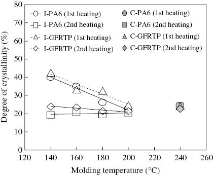
Effect of molding temperature on the degree of crystallinity for the first and second heating for I-PA6 and I-GFRTP.
Generally, crystallization occurs in two stages, namely, the generation of crystal nuclei and the growth of crystal. It is known that a higher temperature leads to greater difficulty in generating crystal nuclei. At a temperature of 140°C, the crystallization showed the highest value because the crystallization that occurred in the polymerization process grew faster owing to the presence of much smaller sizes of nucleus. In contrast, the values of crystallization became smaller at higher temperatures because the crystal nuclei with a smaller size did not grow well. The values of crystallinity after the second heating were smaller than those after the first heating because the I-PA6 and the matrix of I-GFRTP were already highly polymerized and their crystal growth speeds were also already small such that they were almost the same at each molding temperature.
If the results of the I-PA6 and the I-GFRTP are compared, the degree of crystallinity seems almost the same, which suggests that it is not affected by the presence of glass fiber reinforcements.
For C-PA6 and C-GFRTP, the degree of crystallinity was a constant value of around 23% for both the first heating and the second heating. This is probably because the C-PA6 resin and the C-GFRTP matrix were already highly polymerized at the molding process whereby the molecular motion did not differ from the first and second heating processes, namely, no change in the crystal growth speed.
In Figure 6, the case of I-CFRTP showed the same tendency as that of I-GFRTP for the change in molding temperature. The crystallization of I-CFRTP (the first heating) changed from 40% to 25% as the molding temperature increased. The value at 140°C (first heating) was larger than that of C-CFRTP, but the values after the second heating were almost the same as those of C-CFRTP.

Effect of molding temperature on the degree of crystallinity for the first and second heating for I-CFRTP and C-CFRTP.
4.3 Unreacted monomer and water absorption
For the cases of the I-PA6, I-GFRTP, C-PA6 and C-GFRTP, Figures 7 and 8 show the percentage of the unreacted monomer and the water absorption, respectively. From these figures, it can be seen that both the contents of the unreacted monomer and the water absorption were smaller over the molding temperature range between 140°C and 160°C for both I-PA6 and I-GFRTP, and their values were almost the same as the C-PA6 and the I-GFRTP. However, both the contents of the unreacted monomer and the water absorption increased at the molding temperature of 200°C. From these results, there was an appropriate range of polymerization temperature for ε-caprolactam. That is, the matrix resin molded at temperatures of 140°C to 160°C seemed to be highly polymerized such that the contents of the unreacted monomer and water absorption had decreased. For the results of the I-PA6 and the I-GFRTP, there was no difference in the tendency for the contents of the unreacted monomer and the water absorption. This indicates that the glass fibers used as the reinforcement rarely affect the polymerization of the I-PA6 and I-GFRTP.

Content of unreacted monomer of I-PA6 and C-PA6 and of I-GFRTP and C-GFRTP.

Water absorption of I-PA6 and C-PA6 and of I-GFRTP and C-GFRTP.
The water absorption of C-PA6 and C-GFRTP was approximately the same as that of I-PA6 and I-GFRTP molded at 140°C–160°C. This indicates that I-PA6 and I-GFRTP have approximately the same water absorption as C-PA6 and C-GFRTP made from already polymerized polyamide 6.
In Figure 9, the unreacted monomer of the I-CFRTP showed the lowest content at temperatures between 140°C and 160°C, and this value was almost the same as that of C-CFRTP. Figure 10 shows that the water absorption of I-CFRTP at 140°C and 160°C was almost the same as that of C-CFRTP. The optimum molding condition for water absorption was between 140°C and 160°C, which was the same as that of the unreacted monomer.

Content of uncreated monomer of I-CFRTP and C-CFRTP.

Water absorption of I-CFRTP and C-CFRTP.
The range of optimum molding temperature, which was not correlated much with the contents of unreacted monomer and the water absorption, was between 140°C and 160°C for in situ polymerizing ε-caprolactam.
4.4 Bending strength and modulus
Figures 11 and 12 show the bending test result for the I-PA6 and the C-PA6, and for the I-GFRTP and the C-GFRTP, respectively. These figures mean that both the bending strength and the modulus of the I-PA6 and the I-GFRTP showed the highest values when the molding temperature was 140°C–160°C. This dependency of the bending strength and modulus on the molding temperature seemed to be correlated to the lowest unreacted monomer contained in the matrix.

Results of the three-point bending tests for I-PA6 and C-PA6.
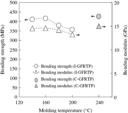
Results of the three-point bending tests for I-GFRTP and C-GFRTP.
In contrast, for the C-PA6 that was prepared for the purpose of comparison against the I-PA6, both the bending strength and the modulus were approximately the same as those of I-PA6 molded at 140°C–160°C. Likewise, C-GFRTP was approximately the same as I-GFRTP molded at 140°C–160°C in terms of both the bending strength and the modulus.
In the case of carbon fabric, the bending strength and modulus of I-CFRTP showed the highest values at the temperature range between 140°C and 160°C, which were the same as those of I-GFRTP in Figures 13 and 14. However, the strength of I-CFRTP was larger than that of C-CFRTP with hot-press molding; the reason for this will be explained in the following scanning electron microscopy (SEM) result.

Bending strength of I-GFRTP and C-CFRTP for molding temperature.
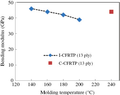
Bending modulus of I-GFRTP and C-CFRTP for molding temperature.
4.5 Impact strength
The impact tests of I-PA6, I-GFRTP and I-CFRTP were performed for the specimens fabricated only at 140°C, and this temperature was the optimum one for the unreacted monomer, water absorption and also the bending properties. Table 1 lists the results of the five specimens for each of the test plates. The symbols “C” and “H” represent the complete brake accompanying a separation of specimen and the partial brake with a hinged style of specimen after the impact, respectively. In the I-PA6, the average value was 2.83 kJ/m2 and all of the specimens showed a failure mode of “C.” In the impact test of I-CFRTP, the no. 3 specimen showed a failure mode of “H” and this value was the maximum value of 26.6 kJ/m2 among the I-CFRTP specimens. The average value was less than half that of I-GFRTP.
Impact strength of various kinds of specimens.
| Specimen number | Izod impact strength (kJ/m2) | ||
|---|---|---|---|
| I-PA6 | I-GFRTP | I-CFRTP | |
| 1 | 2.88 C | 67.8 H | 23.8 C |
| 2 | 2.98 C | 66.2 H | 24.7 C |
| 3 | 2.78 C | 66.2 H | 26.6 H |
| 4 | 2.89 C | 64.0 H | 24.0 C |
| 5 | 2.62 C | 66.6 H | 25.4 C |
| Average | 2.83 | 66.2 | 24.9 |
| Coefficient of variation | 4.4% | 1.6% | 4.1% |
4.6 SEM results
The cross-sectional views of I-GFRTP and C-GFRTP molded at various temperatures are shown in Figure 15. Much of the resin around the glass fibers in the specimen fabricated at 200°C did not remain, but the I-GFRTP fabricated at 140°C and 160°C and the C-GFRTP had a homogeneous impregnation of the matrix over the entire surface of the glass fiber reinforcement without defects such as voids. The monomer of ε-caprolactam used as the matrix of I-GFRTP was well impregnated into the fiber reinforcement because it was still in the state of the monomer with a lower viscosity, so that satisfactory impregnation could be obtained even in the case of using a long-fiber fabric that contains normally a larger amount of fiber reinforcement. Therefore, the in situ polymerizable FRTPs using a monomer of ε-caprolactam as the matrix did not need high-temperature and high-pressure molding systems such as the sheet stacking method, since they could be produced using simpler molding systems with lower energy consumption.

SEM observation of I-CFRTP and C-CFRTP.
From Figure 16, the interface strength of I-CFRTP at 140°C was larger than that of C-CFRTP because much of the resin remained around the fibers. In contrast, the resin around the surface of I-CFRTP at 200°C hardly remained. So the bending properties of I-CFRTP at 200°C became the lowest as shown in Figure 13.

SEM observation of I-CFRTP.
5 Conclusions
In order to apply FRTP to automotive structures, the GFRTP and the CFRTP that use glass plain woven textiles and carbon twilled fabrics as the reinforcement and in situ polymerizable ε-caprolactam as the matrix were newly fabricated with VaRTM. Their crystallites, unreacted monomers and water absorptions were examined according to the change in molding temperatures. Furthermore, three-point bending and impact tests, and SEM observation were performed for both GFRTP and CFRTP. In conclusion, the following items were observed in this study:
In the fabrication of GFRTP and C-FRTP, the molding temperature was considerably lower than the melting point of PA6, and the best molding temperature was from 140°C to 160°C.
The processing time using in situ polymerizing ε-caprolactam as the matrix in the FRTP was much shorter than that using PA6 films because of the absence of a cooling process.
No cooling process leads to a heating process up to the subsequent curing temperature. This method contributes to saving energy in the fabrication technology.
The values of unreacted monomer and water absorption in both FRTPs showed the lowest values at the best molding temperatures from 140°C to 160°C.
The bending strength of GFRTP using ε-caprolactam was almost the same as that of GFRTP using PA6 films.
The bending strength of CFRTP using ε-caprolactam was larger than that of CFRTP with PA6 films because the richer resin remained around the carbon fibers in the specimen fabricated at the best molding temperature.
The impact strength of GFRTP obtained from the Izod edge wise test was twice as large as that of CFRTP.
References
[1] Fu S-Y, Lauke B, Mader E, Yue C-Y, Hu X. Compos. Part A, 2000, 31, 1117–1125.10.1016/S1359-835X(00)00068-3Search in Google Scholar
[2] Rezael F, Yunus R, Barahim A. Mater. Des. 2009, 30, 260–263.10.1016/j.matdes.2008.05.005Search in Google Scholar
[3] Yashiro S, Okabe T, Matsushima K. Adv. Compos. Mater. 2011, 20, 503–517.10.1163/092430411X584423Search in Google Scholar
[4] Studer F. Mater. Des. 1983, 4, 804–808.10.1016/0261-3069(83)90179-6Search in Google Scholar
[5] Parton H, Verposet I. Polym. Compos. 2005, 26, 60–65.10.1002/pc.20074Search in Google Scholar
[6] Parton H, Baets J, Lipnik P, Coderis J, Verposet I. Polymer, 2005, 46, 9871–9880.10.1016/j.polymer.2005.07.082Search in Google Scholar
[7] Nakamura K, Ben G, Hirayama N, Nishida H. Effect of molding condition of impact properties of glass fiber reinforced thermoplastics using in-situ polymerizable polyamide 6 as the matrix. In: Proceeding of ICCM 18, Jeju, Korea, 2011.10.6089/jscm.37.182Search in Google Scholar
[8] Nakamura K, Ben G, Hirayama N, Nishida H. J. Jpn. Soc. Compos. Mater. 2011, 37, 182–189 (in Japanese).Search in Google Scholar
[9] Yan C, Li H, Zhang X, Zhu Y, Fan X, Yu L. Mater. Des. 2013, 46, 688–695.10.1016/j.matdes.2012.11.034Search in Google Scholar
[10] Ben G, Nakamura K, Hirayama N, Nishida H. Development of fiber reinforced thermoplastics composites using in-situ polymerizable polyamide 6 as matrix. In: Proceedings of Composite 2012. American Composites Manufacturers Association: Las Vegas, NV, 2012.Search in Google Scholar
[11] Ben G, Ozeki H, Nakamura K, Hirayama N, Namaizawa M, Kobayashi M, Azuma H. J. Jpn. Soc. Compos. Mater. 2013, 39, 127–134 (in Japanese).10.6089/jscm.39.127Search in Google Scholar
[12] Ozeki H, Ben G, Sakata K. Effects of molding condition on mechanical properties of hybrid FRTYP with VaRTM. In: Proceedings of US-Japan Conference of Composite Materials, Arlington, Texas, 2012.Search in Google Scholar
[13] Dole M, Wunderlich B. Makro Chem. 1959, 34, 29–49.10.1002/macp.1959.020340102Search in Google Scholar
©2015 by De Gruyter
This article is distributed under the terms of the Creative Commons Attribution Non-Commercial License, which permits unrestricted non-commercial use, distribution, and reproduction in any medium, provided the original work is properly cited.
Articles in the same Issue
- Frontmatter
- Original articles
- Experimental study on the mechanical properties of an epoxy-based nanocomposite using polymeric alloying and different nano-reinforcements: nanofiber, nanolayered and nanoparticulate materials
- A new method for preparation of low melting point polyamide-6 (LPA6) and properties of compatibilized blends of LPA6/glass beads/styrene and maleic anhydride copolymer
- The effect of zeolite particle modified by PEG on rubber composite properties
- Investigation of the effect of microstructural parameters on the initial yield surface of non-isothermal composites
- The relationship between geotechnical index properties and the pore-size distribution of compacted clayey silts
- Evaluation of new GFRTP and CFRTP using epsilon caprolactam as matrix fabricated with VaRTM
- Two-step gradation of particle size in an inorganic-organic hybrid
- Degradation of basalt FRP bars in alkaline environment
- Effects of B and V on microstructure of FeCrC cladding layers on the surface of Q235B mild steel by TIG welding
- Microstructural and mechanical properties of Cu-7vol.%ZrB2 alloy produced by powder metallurgy techniques
- Effect of consolidation parameters and heat treatment on microstructures and mechanical properties of SiCp/2024 Al composites
- Experimental investigation of process parameters for WEDM of Ti-6Al-4V/TiN composites
- Three-dimensional natural frequency analysis of anisotropic functionally graded annular sector plates resting on elastic foundations
- Energy absorption rate of composite tube as a function of stacking sequence using finite element method