Development of a high-efficiency and long-life 500W class H-Darrieus-type vertical axis wind turbine (VAWT) system using skin-spar-foam sandwich composite structure
-
Changduk Kong
 and
Haseung Lee
and
Haseung Lee

Abstract
Since the focus on the energy crisis and environmental issues due to excessive fossil fuel consumption, wind power has been considered as an important renewable energy source. Recently, several megawatt-class large-scale wind turbine systems have been developed in some countries. Even though the large-scale wind turbine can effectively produce electrical power, the small-scale wind turbine has been continuously developed due to some advantages; for instance, it can be easily built at a low cost without any limitation of location, i.e., even in the city. In case of small-scale wind turbines, the vertical axis wind turbine (VAWT) is used in the city despite having a lower efficiency than the horizontal axis wind turbine. Furthermore, most small-scale wind turbine systems have been designed at the rated wind speed of around 12 m/s. This aim of this work is to design a high-efficiency 500W class composite VAWT blade that is applicable to relatively low-speed regions. With regard to the aerodynamic design of the blade, parametric studies are carried out to decide an optimal aerodynamic configuration. The aerodynamic efficiency and performance of the designed VAWT is confirmed by computational fluid dynamics analysis. The structural design is performed by the load case study, initial sizing using the netting rule and the rule of mixture, structural analysis using finite element method (FEM), fatigue life estimation and structural test. The prototype blade is manufactured by hand lay-up and the matched die molding. The experimental structural test results are compared with the FEM analysis results. Finally, to evaluate the prototype VAWT including designed blades, the performance test is performed using a truck to simulate various ranges of wind speeds and some measuring equipment. According to the performance evaluation result, the estimated performance agrees well with the experimental test results in all operating ranges.
- Nomenclature
- B
Number of blades
- Ct
Tangential coefficient
- Cp
Wind turbine power coefficient
- C
Blade chord length
- CFD
Computational fluid dynamics
- dz
Length of blade element projected onto the leading edge
- FEM
Finite element method
- H
Half-height of blade
- K
Total sets of applied load cycle
- L
The chord length
- nt
Number of applied load cycles
- P
Power
- Q

- R
Local radius
- R
Maximum blade radius
- S
Projected frontal area of the vertical axis wind turbine
- V1
Uniform wind velocity
- VAWT
Vertical axis wind turbine
- Wu
Resultant air velocity relative to a blade element
- ηg
Generator efficiency
- ηm
Mechanical efficiency
- ρ
Air density
- ω
Angular velocity
1 Introduction
Since the focus on the energy crisis and environmental issues due to excessive fossil fuel consumption has been emphasized, the wind power has been considered as an important renewable energy source. Recently, several megawatt class large-scale wind turbine systems have been developed in some countries. Even though the large-scale wind turbine can effectively produce electrical power, the small-scale wind turbine has been continuously developed due to some advantages; for instance, it can be easily built at a low cost without any limitation of location, i.e., even in the city. In case of small-scale wind turbines, the vertical axis wind turbine (VAWT) is used in cities having frequent wind direction change, even though it has a lower efficiency than the horizontal axis wind turbine. The VAWT can be classified as a differential drag machine like the panemone, Lafond turbine, Savonious, screened machines, machines with flapping blades, machines with turning blades and machines with fixed, movable or cyclic pitch blades such as Darrieus [1]. Among them, the Darrieus-type VAWT, first proposed by Georges Jean Marie Darrieus, uses aerodynamic lift force. The aerodynamics, light structure, fatigue and generation system of the high-performance Darrieus-type wind turbines have been studied in the USA and Canada [2]. For instance, NCR developed the 4 MW class Darrieus-type VAWT in 1988 [3]. Recently, many studies have been performed on the improvement of bad starting behaviors at low wind speed and lower efficiency relative to the horizontal axis wind turbine system [4]. Furthermore, most small-scale wind turbine systems have been designed at the rated wind speed of approximately 12 m/s, but they have a great reduction of aerodynamic efficiency in low-wind-speed regions [5–7].
The objective of this work is to design a high-efficiency 500W class composite VAWT blade that is applicable to relatively low speed regions. In this work, an aerodynamic and structural design procedure, shown in Figure 1, is proposed to design a vertical wind turbine using the skin-spar-foam core sandwich structure having glass/epoxy skin and spar and a polyurethane foam core.

Proposed aerodynamic and structural design procedure.
2 Aerodynamic design
The aerodynamic design of the Darrieus-type rotor including the H-type vertical wind turbine follows Templin’s theory [8–10]. Its maximal power is approximated by the following expression:

where P, S and V are power (W), swept area (m2) and wind speed (m/s), respectively.
The swept area is given as a function of geometrical parameters by the expression:
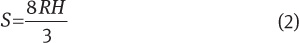
where R and H are the maximum radius and half of the rotor height, respectively.
The tip speed ratio λ0 is approximately related to the ratio R/l by the expression

where b and l are the number of blades and the chord length, respectively.
The power coefficient Cp is defined as

where Ct, Wu, V1, ω, r, z and θ are the parallel Lilienthal aerodynamic coefficient, the tangential component of the relative wind velocity, the upstream wind velocity, the rotor angular velocity, the vertical axis and the horizontal location angle of the blade element.
The aerodynamic power P and the electrical power Pe become respectively by the following expression:

where  W is the relative wind velocity, ρ is the air density, ηg is the generator efficiency and ηm is the mechanical efficiency.
An in-house aerodynamic design program based on the theory above is newly coded using Visual Basic. If the wind speed and design parameters are given as input data, the program can calculate the tip speed ratio, power coefficient and power considering Reynold’s number. Here, the look-up table of the local Reynold’s number of each airfoil is obtained by computational fluid dynamics (CFD) analysis. Figure 2 shows the front page of the aerodynamic design program.

Front page of the proposed user friendly aerodynamic design program of VAWT.
In order to validate the proposed aerodynamic design program, test results are compared with those of the Uppsala University H-type VAWT, which can produce a power of 12 kW with three blades. It has an NACA0021 airfoil, blade length of 5 m, turbine radius of 3 m and chord length of 0.25 m at the rated wind speed of 12 m/s [10]. Figure 3 shows the comparison between the proposed program results and the Uppsala University VAWT test results. Through this comparison, it is confirmed that the proposed program agrees well with the test results.

Comparison between the aerodynamic performance calculation results by the proposed and the test results of Uppsala University VAWT.
The optimal aerodynamic design of the 500W class H-type vertical wind turbine rotor is carried out by the proposed in-house program through a parametric study to find an optimal aerodynamic configuration having high efficiency in both low and high wind speed regions with the following design parameters: number of blades, solidity, airfoil, height-to-radius ratio, etc. Figure 4 shows the parametric case study results with solidity, airfoil, number of blades and height-to-radius ratio. Table 1 and Figure 5 show the optimal aerodynamic design results and the designed configuration using the parametric case study. Figure 6 shows the performance estimation of the power coefficient vs. tip speed ratio and the power vs. wind speed.
Aerodynamic design results of VAWT.
| Rated aerodynamic power (electric power) | 600 W (500 W) |
| Rated wind speed (m/s) | 8 |
| Rated rpm | 168 |
| Number of blades | 5 |
| Radius (m) | 0.9 |
| Blade length (m) | 2.56 |
| Blade chord length (m) | 0.27 |
| Airfoil | NACA0018 |

Parametric case study results with solidity, airfoil, blade number and height to radius ratio.

Designed 500 W VAWT configuration.

Performance calculation results of the designed wind turbine.
Prior to the performance test, the designed wind turbine is numerically analyzed using a commercial CFD code, ANSYS CFX. Figure 7 shows the flow pattern obtained by CFD analysis using this code. In the analysis, input data as an operating condition are the rotational velocity of 167 rpm and the rated wind speed of 8 m/s at sea level. In order to consider the rotating position of the blade, the dynamic moving mesh method is applied. Separate disconnecting zones are used for expressing the rotating and stationary regions. The shear stress transport (SST) turbulence model based on the κ-ω model is used [11]. The analysis ω shows that the calculation power of 663 W meets closely the design target rated output of 600 W.

Stream line distribution for fluid flow analysis using ANSYS.
3 Load case analysis and structural design
According to IEC 61400-2 design requirements for small wind turbines [12], a total of eight load cases are defined. However, this work considers three extreme load cases at normal operation, cutoff condition and standstill and storm conditions among eight load cases. The main loads acting on the blade are the aerodynamic load and the centrifugal force. The centrifugal force can be simply calculated from rotational speed, and the aerodynamic loads defined as the following expressions can be calculated at three load cases mentioned in Table 2.
Definition of load cases considered in structural design.
| Load case | |||
|---|---|---|---|
| Case 1 | Case 2 | Case 3 | |
| Reference wind speed (m/s) | 8 | 20 | 55.0 |
| Gust condition ±(20 m/s, 40°) | Without gust | With gust | Storm |
| Rotational speed | 167 rpm | 353 rpm | Stop |
The components of the aerodynamic force in the chordwise direction and normal to the blade element are

where N, T and cn/ct are the normal aerodynamic force, the chordwise aerodynamic force, and the normal tangential aerodynamic coefficient, respectively.
The shear forces and the bending moments can be defined by integrating the normal and chordwise aerodynamic force component distributions acting on each section of the blade depending on the wind speed and the incidence angle in various operating conditions. Table 2 shows the definition of various aerodynamic load cases having gust conditions and centrifugal body forces considered in the structural design. According to load case analysis, load case 2 is found to be the most severe condition. Therefore, the structural design is performed in consideration of load case 2.
In the structural design, the blade adopts the skin-spar-foam core sandwich structure concept. The glass fabric/epoxy composite material, which is supplied by a domestic company, is used for both skin and spar. The bending force is endured by the spar flange layered with the ply angle of 0°/90°, and the torsion is endured by the upper and lower skins layered with the ply angle of ±45°. Figure 8 shows the blade structural design concept with skin-spar-foam core sandwich. The material properties for skin, spar and core are presented in Table 3.
Mechanical properties of materials used for blade.
| Property | Materials | |
|---|---|---|
| Glass/epoxy fabric | Polyurethane foam | |
| E1, Young’s Modulus 0° (N/mm2) | 10,500 | 60.86 |
| E2, Young’s Modulus 90° (N/mm2) | 10,500 | 59.86 |
| G12, In-plane Shear Modulus (N/mm2) | 1450 | 19.18 |
| ν, Major Poisson’s Ratio | 0.27 | 0.2 |
| Xt, Tensile Strength 0° (N/mm2) | 283.9 | 2.63 |
| Xc, Comp. Strength 0° (N/mm2) | 184.6 | 1.41 |
| Yt, Tensile Strength 90° (N/mm2) | 283.9 | 2.49 |
| Yc, Comp. Strength 90° (N/mm2) | 184.6 | 1.41 |
| S, In-plane Shear Strength (N/mm2) Density (g/cc) | 15.0 | 0.71 |
| S, In-plane Shear Strength (N/mm2) Density (g/cc) | 1.705 | 0.1197 |
| Ply thickness (mm) | 0.25 | 12.5 |

Structural design concept of blade with skin-spar-foam core sandwich.
The initial design of the composite blade is carried out using the netting rule and the rule of mixture, which were used in the previous study [5–7], and then the designed feature is repeatedly modified by structural analysis results using a commercial finite element method (FEM) code, NASTRAN. The blade section profile shape is constant along the spanwise direction because it has the same relative wind velocity and angle of attack during operation. The thicknesses including lamination sequences for skin, spar and core are the same for easy manufacturing and design. Therefore, its weight may increase a bit. The lamination sequences of skin, spar and core are shown in Table 4.
Designed lamination sequence and thickness.
| Lay-up sequence | Thickness (mm) | |
|---|---|---|
| Skin | ±457 (Glass/epoxy fabric) | 1.75 |
| Spar | (0/90)13 (Glass/epoxy fabric) | 3.25 |
| Core | (Polyurethane foam) | 40.5 (max) |
In the FEM analysis, stresses, strains, tip deflections, buckling loads and natural frequencies are found. Skin, spar and core of the blade structure are meshed by 3584 PCOMP four-node shell elements, which can have good composite structural behaviors. In the FEM analysis, the aerodynamic loads calculated by the developed in-house code for the aerodynamic design are directly applied to the FEM model, and the centrifugal body force is applied to the model by the centrifugal body force application method of MSC NASTRAN using rotational speed, the centripetal center and blade mass. The aerodynamic loads are applied on the aerodynamic centers of the spanwise distributed blade airfoils, and the boundary condition is assumed as a fixed condition at the joint part between the connection support and the blade root. Figure 9 shows the FEM mesh generation results using PCOMP four-node shell elements.
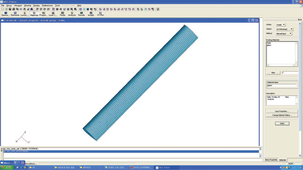
FE mesh generation results using PCOMP 4-node shell elements.
The results show that the highest stresses occur at the 1st ply of the skin and the 13th ply of the spar, respectively. Figure 10 shows the spanwise (y axis) stress contour on the blade illustrated by FEM analysis. Table 5 shows structural analysis results of the fiber direction at the 1st ply of the skin and the 13th ply of the spar. In order to check the resonance possibility, eigenvalue analysis is performed using FEM code MSC NASTRAN. Figure 11 shows the estimated natural vibration mode shapes and frequencies. To check the possibility of resonance, the Campbell diagram is drawn. Because all the five low natural frequencies do not coincide with the operating rotational speed of 167 rpm, resonance may not occur during operation shown as Figure 12.
Stress analysis results of small VAWT blade.
| Analysis result | Blade components | ||
|---|---|---|---|
| Spar | Skin | Connection support | |
| Max stress (MPa) | |||
| Ten. | 12.4 | 94.4 | 259 |
| Comp. | 21.1 | 92.8 | |
| Max stress failure criterion | |||
| Ten. | 0.04 | 0.3 | 0.91 |
| Comp. | 0.11 | 0.5 | |
| Tsai-Wu failure criteria | 0.23 | 0.78 | |

Spanwise (Y-axis) stress contour on the 13th ply of spar for load case 2 (MPa).

Natural vibration mode shapes and frequencies.

Campbell diagram to check resonance possibility.
Wind turbine blades should withstand the repeated fatigue loads during the required fatigue life operation. In this work, the load spectrum is obtained using the aerodynamic design program and the wind speed data were measured at Ganyeoam, Yeosu, Jeollanam-do in Korea. The measured wind speed data are divided into 13 intervals. In the load spectrum analysis, it is assumed that the rotor blade load is not produced at a wind speed of <2 m/s as well as more than 20 m/s. The rotational speed and the blade load at various wind speeds are calculated with the proposed aerodynamic design program. The 20-year cycles at each wind speed region are calculated from the rotational speed and the required fatigue life. The normalized cycles at each wind speed region are obtained from the cycles during 20 years divided by the cycles during maximum wind speed region of 20–40 m/s. Table 6 shows the load spectrum obtained by the aerodynamic design program and the wind data measured in a local Korean province, and Figure 13 shows the load spectrum calculated by the proposed load spectrum estimation program with the previously explained procedure using EXCEL.
Load spectrum obtained by the aerodynamic design program and the wind data measured at Ganyeoam, Yeosu, Jeollanam-do in Korea.
| Wind speed (m/s) | Operating time years (h) | Load/max load | Cycles during 20 years | Normalized cycles (divided by cycles during max wind speed region) | |
|---|---|---|---|---|---|
| Max | Min | ||||
| 2–3 | 1151 | 0.006 | -0.004 | 8×10⁷ | 12 |
| ∼4.5 | 935 | 0.13 | -0.01 | 1×10⁸ | 14 |
| ∼6 | 1022 | 0.023 | -0.018 | 1×10⁸ | 21 |
| ∼7.5 | 926 | 0.036 | -0.028 | 2×10⁸ | 30 |
| ∼9 | 881 | 0.052 | -0.04 | 2×10⁸ | 23 |
| ∼10.5 | 770 | 0.071 | -0.054 | 2×10⁸ | 24 |
| ∼12 | 626 | 0.092 | -0.071 | 2×10⁸ | 26 |
| ∼13.5 | 524 | 0.117 | -0.09 | 2×10⁸ | 25 |
| ∼15 | 400 | 0.144 | -0.111 | 1×10⁸ | 21 |
| ∼16.5 | 213 | 0.175 | -0.134 | 8×10⁷ | 12 |
| ∼18 | 127 | 0.208 | -0.167 | 6×10⁷ | 8 |
| ∼20 | 100 | 0.244 | -0.187 | 4×10⁷ | 7 |
| 20–40 | 97 | 0.009 | 0 | 6×10⁶ | 1 |
| Total | 7772 | 1×10⁹ | |||
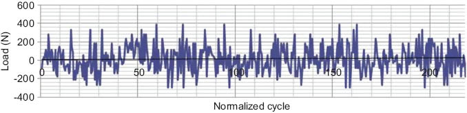
Normalized load spectrum calculated by the proposed load spectrum estimation program.
The required fatigue life is more than 20 years, and the fatigue life is estimated by Miner’s rule [12–16]. The cumulative damage is calculated using the S-N curve of the applied composite materials and the obtained load spectrum. The fatigue life can be estimated using Miner’s rule.
From stresses calculated by the load spectrum and the S-N curve used for spar shown as Figure 14, the fatigue life Ni at average stress level Si can be estimated. If the number of applied load cycles ni at average stress level Si is given, the required 20-year fatigue life can be confirmed by Miner’s rule: If the blade is accumulatively used at average? stresses Si during ni times, its fatigue life safety is evaluated by the following formula:
![Figure 14 S-N diagram for composite materials of spar [10].](/document/doi/10.1515/secm-2012-0110/asset/graphic/secm-2012-0110_fig14.jpg)
S-N diagram for composite materials of spar [10].
where k; total sets of applied load cycles at constant stress level Si.
If  <1 is safe from the fatigue, while
  ≥1 is unsafe from the fatigue. In the present study, the number of cycles and fatigue loads are obtained from the previously obtained fatigue load spectrum, and the fatigue lifelife Ni at stress Si is calculated by the S-N diagram of the glass/epoxy composite material. Therefore, because the calculated value of 0.7 is less than 1, the designed wind turbine blade has more than the required fatigue life of 20 years.
4 Manufacturing of prototype blade and structural test
In manufacturing, the hand lay-up and the matched die molding methods are applied [3]. In the manufacturing process, the styrofoam mold is first manufactured using steel plate templates and hot wires due to economic reasons, and then glass fabrics for the second mold are layered up on the styrofoam mold with a special coating. Again the glass fabrics are layered on the second mold for the final mold, and then glass fabrics for the upper and lower surface skins of the blade are layered on the final mold according to the structural design result. The cured upper and lower surface skins are bonded by epoxy, and then the polyurethane foam is injected into the space between the upper and the lower skins. After the blade is completely cured, the proper coating is applied. The manufacturing process and the first prototype blade are shown in Figure 15.

Applied manufacturing process and the first prototype blade.
The design loads for the static structural test are simulated by the three-point loading shown in Figure 16. The test is performed by the structural test equipment shown in Figure 17. The test results are compared with FEM structural analysis results. The deflection measured at the blade center is 51 mm, and the estimated deflection at the same position is 54 mm. The upper and lower surface spanwise strains measured at 50 mm from the blade center are 1060 μɛ and 870 μɛ, respectively. Estimated results at the same locations are 1010 μɛ and 762 μɛ, respectively. Figure 16 shows static strength test loads simulated by the three-point loading method, and Figure 17 shows a picture of the static structural test using three-point loading. In the structural experimental test, the aerodynamic loads are simulated using the three-point loading method shown in Figure 15 because the loading actuation system is limited. Therefore, the simulated bending moment is slightly different from the aerodynamic bending moment. It is surmised that the mesured deflection at the blade center is a bit smaller than the estimated deflection due to the constraint of the loading actuator, but the measured strain on the 50-mm position from the blade center is slight higher than the estimated results due to the simulated loading and incorrect dimension and surface treatment by unskilled hand lay-up manufacturing experience.
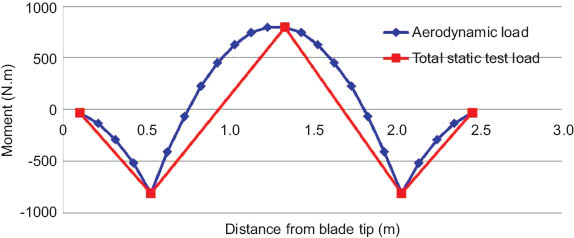
Static strength test loads simulated by the 3-point loading method.

Static structural test of the prototype blade using the 3-points loading.
5 Performance test of prototype small VAWT
To evaluate the target design performance, the performance test of the prototype small VAWT is done using a test purpose tower, generator, electrical loader, performance measuring instruments, etc. Because the wind tunnel for the aerodynamic test of the full-scale wind turbine system is not available, a truck is used for the performance test. In order to simulate various wind speeds, the truck is specially controlled by various speeds. The simulated speed range on the truck is 3–11 m/s. However, even though some errors in wind speed are expected due to measurement at a different location from the wind turbine blades, they are negligible because the measuring location is near the test machine.
To measure the electrical power produced by the wind turbine, a gearless generator SYG-A208-600-570 [14], which has some advantages such as simplicity due to lack of gears, easy blade mounting and low noise, is used. Additional test devices are a rectifier, resistances for electrical loading, a multimeter and a photosensor and an instrument to measure the blade rotational speed. Figure 18 shows the test setup for performance test of the prototype VAWT. Figure 19 shows the comparison between experimental test results and estimation results of electrical power produced by the prototype VAWT. In the test, the wind turbine starts to produce the electrical power from approximately 3 m/s, and the power is limited at approximately 700 W due to the limited power of the 500-W generator and its power control system. However, the developed wind turbine produces the design power of 500W at the rated wind speed of 8 m/s. This result reveals that the test result agrees well with the estimation result in all operating ranges.
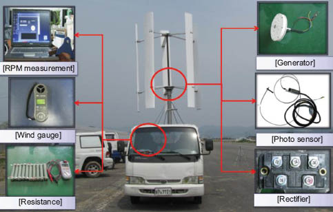
Test setup for performance test of prototype small VAWT.
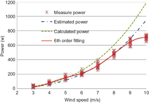
Comparison between test results and estimation results of electrical power produced by prototype small VAWT.
6 Conclusion
In this work, the aerodynamic and structural design procedure of a high-efficiency 500W class composite VAWT is proposed. In the aerodynamic design of blade, parametric studies are carried out to decide an optimal aerodynamic configuration.
The aerodynamic efficiency and performance of the designed VAWT is confirmed by CFD analysis. The structural design is performed by the load case study, the initial sizing using the netting rule and the rule of mixture, the structural analysis using FEM, the fatigue life estimation and the structural test. The prototype blade is manufactured by the hand lay-up and matched die molding. The experimental structural test results are compared with the FEM analysis results.
Finally, to evaluate the prototype VAWT including designed blades, the performance test is done using a truck to simulate the various wind speeds and some measuring equipment. According to the performance evaluation result, the estimated performance agrees well with the experimental test results in all operating ranges.
This work was supported by research funds from Chosun University, 2013.
References
[1] Kim KH, Lee JO. Trans. KSME B 1979, 3, 60–67.10.1029/EO060i006p00067Search in Google Scholar
[2] Templin RJ. Aerodynamic Performance Theory for the NRC Vertical Axis Wind Turbine. LRT-LA 160. National Research Council: Canada, 1974.Search in Google Scholar
[3] Project Eole – a retrospective. Bulletin, October 1983.Search in Google Scholar
[4] Pourboghrat F. Symposium on Bio-fuels and Wind Energy, Michigan State University, December, 2010.Search in Google Scholar
[5] Kong C, Bang J, Sugiyama Y. Energy 2005, 30, 2101–2114.10.1016/j.energy.2004.08.016Search in Google Scholar
[6] Kong C, Kim T, Han D, Sugiyama Y. Int. J. Fatigue 2006, 28, 1382–1388.10.1016/j.ijfatigue.2006.02.034Search in Google Scholar
[7] Kong C, Choi S, Park H. Adv. Compos. Mater. 2011, 20, 105–123.Search in Google Scholar
[8] Eggleston DM, Stoddard, F. Wind Turbine Engineering Design, Van Nostrand Reinhold Co. Inc., 1987.Search in Google Scholar
[9] Le Gourieres D. Wind Power Plants: Theory and Design, Pergamon press, 1982.10.1016/B978-0-08-029966-2.50014-6Search in Google Scholar
[10] Solum SA, Bernhoff H, Leijon M. Renewable Energy 2008, 33, 674–681.10.1016/j.renene.2007.03.027Search in Google Scholar
[11] Lee WL, Kim DH, Park GG, Oh MW, Choi HC, Kim YH, Kim SH. In: Proceedings of the 2010 International Symposium, Yanbian University of Science & Technology, 28 June, 2010.Search in Google Scholar
[12] IEC 61400-02. Part 2: Design Requirements for Small Wind Turbine, IEC, 2006.Search in Google Scholar
[13] IEC 1400-1. Wind Turbine Generator System. Part I. Safety Requirement, 1st ed., IEC, 1994.Search in Google Scholar
[14] Seoyoung Tech. Available at: http://www.evsmotor.co.kr. Accessed 11 May 2010.Search in Google Scholar
[15] Miner MA. J. Appl. Mech. 1945, 12, 159–164.Search in Google Scholar
[16] Mandell JF, Reed RM, Samborsky DD. Fatigue of Fiberglass Wind Turbine Blade Materials, SAND92-7005, Sandia National Laboratories: Albuquerque, NM, 1992.Search in Google Scholar
©2013 by Walter de Gruyter Berlin Boston
This article is distributed under the terms of the Creative Commons Attribution Non-Commercial License, which permits unrestricted non-commercial use, distribution, and reproduction in any medium, provided the original work is properly cited.
Articles in the same Issue
- Masthead
- Masthead
- Original articles
- Wetting and the reaction of multiwalled carbon nanotube-reinforced composite solder with a copper substrate
- Microstructural characteristics of SiC-B4C reinforced laser alloying composite coatings
- Effect of reinforcement percentage on wear behavior of SiCp reinforced ZA43 alloy metal matrix composites
- Prediction and optimization of stability parameters for titanium dioxide nanofluid using response surface methodology and artificial neural networks
- Heat-resistant antiflaming and friction mechanisms in nano-Fe2O3-reinforced silicon rubber
- Properties of orchard pruning and suitability for composite production
- Hybridization effect on mechanical properties of short basalt/jute fiber-reinforced polyester composites
- Influence of fungal infection on the long-term water absorption and morphological behavior of bagasse fiber/polypropylene composites at different exposure times
- Vibration analysis of sandwich beams with variable cross section on variable Winkler elastic foundation
- Utilization of water reed in production of various insulation panels
- Synthesis of AA-based SAR interpenetrated with PVA and AM
- Development of a high-efficiency and long-life 500W class H-Darrieus-type vertical axis wind turbine (VAWT) system using skin-spar-foam sandwich composite structure
- The effects of cement and natural zeolite additives on problematic clay soils