Study on vibration monitoring and anti-vibration of overhead transmission line
-
Weihua Yin
 and
Li Lin
and
Li Lin

Abstract
Numerous forms of dampers are used to eliminate the vibrations in transmission lines. In the contemporaneous editorial, a survey has been done on vibrations monitoring and anti-vibration of overhead transmission line of transmission lines having multiple dampers for dissimilar cable sizes. To investigate the outcome of the position of dampers on extreme strains created in the line. A comprehensive survey of the extreme strains created is also made for several wind power input conventions. A finite element technique is used to measure the frequency and manner figures of the cable with and without a damper. The response of the bare conductor, loaded conductor, the conductor for various dampers’ location is also studied. Spoilers and torsional dampers are maximum actual in diminishing electrode galloping, while dampers are quite the utmost effectual plans for aeolian shakings and spiral dampers are admirable for identical lesser width of electrodes.
1 Introduction
The enticement of wind is caused for wind vibration of overhead transmission lines. It indemnities conductors, equipment, and towers, which may be the reason fire and protection of public's life and goods [1]. Dampers are extensively used in transmission lines to diminish wind shaking levels to the safe level. The quantity and location of dampers on transmission lines are mostly resolute by investigated on the foundation of the energy balance principle [2]. The run-through particularly cannot precisely deliberate the end product of fixing the position of dampers and their active features. A proportion of hypothetical investigation about dampers. Nevertheless, it immobile seems broken stocks, the defeat of damper hammers, stern bending of steel strand produced by the wind shaking in genuine engineering. The inland investigation on joined shaking of transmission line and damper system is not sufficient [3]. The outcomes are not beneficial to industrial applications and absence active computer-aided design series around wind shaking. To eliminate vacillations in overhead transmission lines dampers are used transmission lines. Because of laminar wind, overhead transmission lines will be agitated [4]. Oscillations can lead to harm to the conductor. To diminish these vibrations and oscillations to an indiscriminating dimension, curbing systems will have to be connected in the overhead transmission lines. A Stockbridge damper is a modified mass damper used to eliminate wind-induced shakings on trim constructions for example above power lines and extended cantilevered signs. The dumbbell-shaped convenient contains dual masses at the culmination of a small dimension of cable or elastic pole, which is compressed at its internal to the foremost cable. The damper is designed to dispel the vitality of oscillations in the key cable to a satisfactory level. Its idiosyncratic figure provides it the name “dog-bone damper” [5]. To neutralize vibrations animated by the wind, supposed Karman vibrations. Contingent on the form of the rod, numerous damper kinds with numerous dissimilar simulations are obtainable. The term of the damper is because of the researcher H. Stockbridge [6], who progressive the extension of the damper in the 1920s. Spacers assist to create expanse among the limited conductors of a bundle line to avert the conductors from bumping together. Therefore evade damage done to conductors. Spacer dampers will be used if vibrations animated by wind need to be predictable. Damping [7] essentials amid the frame and the conductor clamps, the vibration generosities of the conductor can be abridged to a credulous facet. Numerous dissimilar prototypes of the inserts are obtainable for dissimilar bundle preparations. Wind-induced quivering [8] of the above conductors is conjoint worldwide and can reason conductor exhaustion nearby a hardware supplement. The essential for the transmission of message signals rise, several Optical Ground Wires (OPWG) are changing outdated ground wires. All Aluminum Alloy Conductors [9] (AAAC) have been a current optimal for the above conductors because of the compensations in both electrical and motorized features. Inappropriately AAAC is recognized to be disposed to Aeolian vibration. Shaking dampers are extensively used to mechanism aeolian shaking of the conductors and earth wires containing OPGW [10? –13]. Figure 1 shows the Spiral vibration damper. The high tension to mass ratio allows AAAC conductors to be pass through at advanced tension and extended spans than outdated ACSR (Aluminum Conductor Steel Reinforced) conductors. Inopportunely the self-damping of the conductor declines as tension rises. The wind control into the conductor rises with span dimension. Hereafter AAAC conductors are probable to involve more unembellished shaking than ACSR.

Spiral vibration damper
The essential for the transmission of message signals rise, several Optical Ground Wires (OPWG) are changing outdated ground wires. All Aluminum Alloy Conductors (AAAC) have been a current optimal for the above conductors because of the compensations in both electrical and motorized features [12]. A comprehensive survey of the extreme strains created is also made for several wind power input conventions. A finite element technique is used to measure the frequency and manner figures. This study aims to investigate the suppression schemes for a large crossing span of UHV eight-bundle conductor aeolian vibration.
First, the general conception of aeolian and the analytical models for the conductor, vibration-dampers, and damping wire is demonstrated.
Second, the equation of the energy balance method is introduced and terms in the equation are determined.
The article is thus organized in the following order. Literature reviews of various techniques and precession farming are detailed in Section 2. Section 3 discusses the vibration equation and model analysis. Methods of vibration control are discussed in section 4. The use of a damper is discussed in section 5. Finally, the manuscript is concluded in Section 6.
2 Literature review
The aeolian vibration of ground wires proceeds abode in a broad frequency varies of 6.3 to 111 Hz, contingent on the geometric airstream speed and ground wire constraints. Besides, a slightly stable airstream can reason aeolian shaking at a consistent frequency. Aeolian shaking is categorized by extended period. Understanding land and meteorological conditions demonstration that there can be extreme shaking at any instant in lines placed in level and blustery areas. Dampers were extensively used to overwhelm the aeolian shaking on above-ground wires meanwhile in the 1950s, which rough copy map. It is consists of three portions as presented [13]. The dampers show significant consequences to destroy the aeolian shaking, though approximately restrictions are accessible communication system. Anti-vibration influence is not perfect. The superior frequency of the ground wires on transmission lines with a size below 100 mm2 is normally above 100 Hz that needs the damper's extra broad resonance frequency range. While the FG-type damper has individual dual significance frequencies for its regular loads [14]. When the shaking frequency of the ground wires surpasses the frequency in smooth and blustery areas. The crushed wires at the clamp happen bulge and exhaustion breaking may happen [15]. The compress effortlessly slip-ups the grasp consequence on ground wires is not real since its iron-plate kind clamp holds the ground wires by revenue of the line interaction nearly. The clamp moveable owing to material move stealthily, which may reason ground wires smashing if not attached suitably [17]. Messenger cables are effortlessly stained. The tack hammer dampers are empty-cylinder type, its envoy cords are in biochemical and manual incorporation erosion in wide period because air pollution and another force act. The erosion will lead to the forte and inflexibility abridged and the resistance reduced. So the mallets are informal to sag afterward durable process and the anti-shaking consequence decay extremely [18]. To attain the finest anti-shaking result of the damper, it should be the code that the dispatch rider cables can crop extreme ricochet to ingest extra vitality in the assortment and fixing of the damper. Consequently, the ordinary frequency of the inhibition must be well-suited with the probable shaking frequency varies of the above lines to drive when shaking happens [19]. Typically impediments on EHV lines cannot destroy aeolian shaking well, so inhibitions with improved intended construction and a better frequency vary essential to be advanced as a spare for dampers. The damper, with adjustment fork-molded mallet and indiscretion abidance, was recognized [20]. The bulk of mallet and measurement of the envoy wires on the dual margins of fastening are unequal. An extra consequence can be attained by mixture inhibition.
To come across the greater necessities of shaking conquest in the Hexi lines, two types of FR-type inhibition with a mound hold were recognized. Figure 2 shows the general flow chart for the optimization of a Stockbridge damper. Initially, the frequency was intended rendering to the line factors and climate. Then, the impediments were envisioned creating on practices and philosophy [21].

General flow chart for the optimization of a Stockbridge damper
Thirdly, type trials were done and improvement was comprehended. A photo of the novel damper is obtainable in Figure 3. The mound clamp clenches the ground wire. During galloping, conductors at the suspension insulators can move along the line with amplitudes of up to 1 m, depending on insulator length. Thus, if not long enough to accommodate such motion, the ground lead will be stressed by these repeated movements. Stress-relieving clamp designs such as over armor rods reduce local stresses in-ground leads while some utilities even use a polymeric insulator in parallel with the slack ground lead to relieve strain associated with conductor and ground lead motions due to wind. That type of configuration has offered reliable long-term performance at the cost of only an additional 230 kV polymeric insulator, energized only if the arrester fails. This is the same configuration as the insulated hanger for distribution arrester designs

The novel Stockbridge dampering (a) and (b).
3 Vibration equation and model analysis
The transmission line can be elementary as tensioning beam with minor difficulty, and shaking. The equation can be inscribed as Eq. (1) [22]. The cord shaking model is secondhand to feign transmission line disregarding cable rigorousness as the extent of a transmission line is equal to a few meters [23]. Figure 4 shows the Stress investigation of the vibration conductor. The transmission line is abridged as an extended solid cylinder, whose symmetrical and substantial goods unaffected end-to-end extent of the transmission line and twisting inflexibility unnoticed. Therefore, the transmission line's vibration equation underneath the accomplishment of straight wind is engraved as Eq. (2).

Stress investigation of vibration conductor
The component rigorousness matrix and strain stiffness matrix are articulated.
Them is excellence of constituent length of line, Y is the movement of wind shaking, c is checking constant, T is normal stiffness, p(t) is excitation force, x is longitudinal organizes lengthways, n(x) is the position of the Nth damper, N f (t)is the consequence of dampers, Q is trim force, M is winding instant, A is the area, F is the amount of component early pretentiousness and additional axial force, L is the measurement of the unit, 1 C is ductile and condensation stiffness number, 2 C is stress arduousness constant. Once the unit draws, both 1 C and 2 C value1.0, when the unit is pushed, together 1 C and 2 C value 0.0
4 Result and discussion
Prevalent approaches of plummeting vibrations of power line performers can be alienated as follows: sleek structural approaches and mechanical approaches. Normally used apparatus for damping in the airpower line conductor vibrations comprises dampers of type Stockbridge, spiral dampers, torsional dampers, and spacers with damping possessions. Designated, actual mechanical dampers are labeled underneath. Stockbridge dampers are the utmost regularly used inhibitions on above your head power lines [24]. A typical Stockbridge damper contains dual ‘inertial masses’ fastened at the split ends of a mainly proposed small steel cord strand involved with a fasten to the checked conductor [25]. The dynamism of ambiances is degenerate over resistance caused by slippage among the messenger wires. When the damper is located on a vibrating conductor, the erect motion of the heaviness forces the steel conductor to bend, producing friction among the wires which dissolves the energy. The weights and damper geometrics affect the measure of energy degenerate for exact vibration occurrences [26]. A better form of the definitive damper topographies two dissimilar masses in the form of a bell, situated unevenly at the finishes of a steel galvanized messenger of perchance the best energy debauchery possessions [27]. Such a design of the damper doubles the number of character peaks from two obtained with the classic version of the Stockbridge damper to four in the improved version [28]. Modern Stockbridge dampers are envisioned for real energy assignment and debauchery for the entire spectrum of frequencies inside aeolian vibrations. To confirm actual damping, the first damper should be situated next to the supplement inside the shortest loop which is shaped at the maximum speed of wind (7 m/s). The Spiral Damper has been practical on minor diameter conductors (≤ 19 mm) for over 30 years. It is complete of uneven non-metal substantial in the technique of spiral of length 1.2 – 1.5 m, with an interior diameter beyond the conductor diameter. A spiral at the one end observes strappingly to the conductor [29,30,31,32]. Throughout aeolian vibrations, the restraining part of this spiral influences the conductor and reasons creation of impulses that upset conductor vibrations. An additional type of spiral hindrance is the Air Flow Spoiler. The Detuning Pendulum is used for single cables and cables in a bundle. A typical design of the damper is a weight attached to a cable or cable bundle. The length of the arm and weight depends mainly on the cable diameter and span length. Arm length and mass mandatory to the overwhelmed instant of ice and wind load, thus diminishing galloping. This damper separates frequencies of vertical vibrations from frequencies of torsional vibrations. Three-four dampers are connected along the span, using braids to decrease local cable tensions. It syndicates belongings of a torsional damper and detunes [33]. This damper uses a torsional motion of a conductor during galloping to damper vibrations and improves its effectiveness by separating frequencies of vertical vibrations from frequencies of torsional vibrations, as in pendulum dampers. This damper upsurges the worth of hustle of wind, overhead which galloping happens, and decreases its amplitudes.
For controlling galloping for single conductors and for controlling aeolian vibrations (in conductors of small diameters and spans) can be used AR Twister dampers. Three types of AR Twisters are manufactured: Piston, Kanister, and Slider Twisting is the main technique for galloping control in all these dampers. All AR Twister dampers reduce or eliminate galloping of a conductor by making the conductor rotate and – as a consequence – decrease the aerodynamic lift. The AR Twister is an inertial device made of [33]. Damping required to control aeolian vibrations is achieved by rubbing metal with metal, as a result of slight motions between the device body and its clamp. These devices are rigidly fixed to the conductor with standard vertical clamps or clamps which are angled at 45° to 60°. Such an arrangement of dampers causes an initial torsion of the conductor under gravity forces. In the event of galloping, inertial forces affect the device making the conductor twist again, in the opposite direction to its initial position.
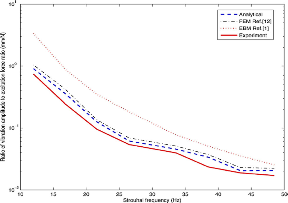
Table 1 and 2 show the: high-performance conductors and their specifications. When galloping, torsional oscillations increase, ice sediment is distributed over the greater surface of the conductor and the profile becomes smooth and less eccentric. At the same time, the aerodynamic lift force is reduced and the level of vibrations decreases. It is perceived from Figure 5 that the vigor balance scheme overvalues the retort of the unembellished electrode, through Figure 6 specifies that it underrates the retort of the encumbered conductor. The conspiracies in Figures 5 and 6 also demonstrate that the proportion of the trembling amplitude to the excitation force knowingly reductions with cumulative frequency. Though, the shuddering response of the electrode with the involved Stockbridge damper is much inferior to that of the naked conductor. For an excitation frequency of f ¼ 26.5 Hz, Figure 7 demonstrates the period retort turn of the electrode for numerous dampers’ locations. The vibration amplitude is suggestively concentrated by attaching a Stockbridge damper at mid-span. A span length of Lc ¼ 366m is designated for the subsequent mathematical instance. This miscellany confirms that the relation of the electrode slump to span length is characteristic of the prevailing transmission line. The equivalent wind force F0 ¼ 370.9 N. Figure 8 largess the no dimensional retort of the conductor. It is perceived that the electrode retort reduces when the Stockbridge inhibition is attached except for f ¼ 12.19 Hz which demonstrations a minor surge in the anode retort. The cause for this upsurge is as the position of the impediment for this exact frequency resembles a knob.
High performance conductors and its specifications
| Conductor cross section & type | ACSR 20/35 | ACSR 300/50 | ACSR 680/85 | AAAC 120 | AAAC 185 | AAAAC 241 |
|---|---|---|---|---|---|---|
| Standard | EN 50182 | EN 50182 | EN 50182 | EN 50182 | EN 50182 | SS 4240811 & SS 4240812 |
| Construction (n×mm) | 26×3.2al 7×2.49 St |
26×3.86 Al 7×3.0 St |
54×4.0 Al 19×2.4 St |
19×2.8 | 37×2.5 | 19×4.02 |
| Diameter (mm) | 20.3 | 24.4 | 36 | 14 | 17.5 | 20.1 |
| Weight (kg/km) | 844.1 | 1227.3 | 2549.7 | 321.2 | 500.3 | 663 |
| Breaking load (min) | 73.36 | 105.09 | 206.25 | 34.51 | 53.58 | 61.6 |
| Max. ratio (tension to weight) | Before creep: 2100 After creep 1670 |
Before creep: 2100 After creep 1670 |
Before creep: 2100 After creep 1670 |
Before creep: 1230 After creep 1100 |
Before creep: 2100 After creep 1780 |
Before creep: 2100 After creep 1780 |
| Regular Suspension clamps will include rods | + | − | − | − | − | − |
| Suspension clamps shall be AGS type | − | + | + | − | − | + |
| Length of the armor rod | 1930 | 1700 | 2235 | − | − | 1524 |
| Wedge tension clamp | + | + | + | + | + | + |
| Post insulators distribution ties | − | − | − | Length is 600mm | Length is 900mm | − |
Specification NCS 163 for Stockbridge type vibration dampers for distribution and transmission overhead lines
| Conductor cross & type | AAAC AL59 593 | AAAC AL59 774 | AAAC AL59 362 | AAAC AL59 118 | OPGW 245 |
|---|---|---|---|---|---|
| Standard | SS 4240813 & SS 4240813 | SS 4240813 & SS 4240814 | EN50182 | Specification NCS-8 | Specification NCS-8 |
| Construction | 61×3.52mm | 61×4.02mm | 37×3.52mm | − | − |
| Diameter | 31.7 | 36.2 | 24.71 | 14.84±0.26 | 20.58±0.36 |
| Cross section of conductor (mm2) | 593.6 | 774.2 | 362.1 | 118 | 245 |
| Breaking load (kN) | 143 | 178 | 86.91 | 40 | 70 |
| Max. ratio (tension to weight) | Before creep: 2100 After creep 1670 |
Before creep: 2100 After creep 1670 |
Before creep: 1230 After creep 1100 |
Before creep: 2100 After creep 1780 |
Before creep: 2100 After creep 1780 |
| Suspension clamps shall be AGS type | − | − | − | + | −+ |
| Suspension clamps shall be AGS type | + | + | − | − | + |
| Length of the armor rod | 2235 | 2235 | 1700 | 1140 | 1550 |
| Wedge tension clamp | + | + | + | + | + |
| Tension shall be with helical end type | − | − | − | − | − |
Corroboration for the undecorated electrode

Shuddering retort of a archetypal extent length of transmission line

Corroboration for the full conductor (Ld = ¼ Lc)

Meandering strain of a characteristic extent length of transmission line
5 Applications of dampers
Permitting to the concert features of the ground wire damper and mound damper, shared with involvement in the joining of ground wire dampers, the novel inhibitions were fit in agreement with the next values [33].
Ground wires in individual circuit lines, one FR-2 damper was predisposed on apiece cross of the extents below 300 m;
One FR-2 and one FR-3 damper
One FR-3 damper and two FR-2 dampers
The detachment among together dampers was 0.75 m, with an equivalent detachment among fitted dampers.
For ground wires in dual circuit lines, one FR-2 and FR-3 damper were close-fitting on spans below 300 m, and expedients that joint damper and damping cable were equestrian on spans above 300 m.
In total, above 12 000 sets of mound inhibitions were used from the foot by mound armor stick, it suitable, secure, and slip-resistant. Since the novel clamp averts stress absorption by armor rod in its place of a screw, it can diminution subtleties bendy straining at the clamp.
6 Conclusions
Shakings of above power line conductors produced by airstream may cause their obliteration. Consequently, decreasing the near of such feelings is significant owing to care of the whole edifice. Communal approaches of deprecation of conductor sensations are unreceptive: good decisive of the exterior shallow of an electrode, a good proposal of the self-damping and use of unusual hindering devices, contingent on the kind of excitations. Now, there is no one way to entirely diminish shakings through galloping, for which amplitudes may spread high standards. Permitting to the investigation works. Spoilers and torsional dampers are maximum actual in diminishing electrode galloping, while dampers are quite the utmost effectual plans for aeolian shakings and spiral dampers are admirable for identical lesser width of electrodes. It is also perceived that the supplement of the Stockbridge damper significantly decreases the trembling retort of the electrode. The grade of decrease needs on the position and the figure of the Stockbridge damper. Now, there is invincible to entirely decrease ambiances through galloping, for which amplitudes may spread high morals. Airflow spoilers and torsional curbs are of utmost actual in diminishing electrode galloping, while Stockbridge inhibitions are immobile the supreme effectual plans for aeolian ambiances and spiral hindrances are brilliant for actual minor width of electrodes. A new area of research that can be analyzed with the better control algorithm with the suitable dampers and actuators for the outrigger structural control. The adaptive control, stochastic optimal control, and robust control techniques can be incorporated for the control of the damped outrigger structure and other structural forms with the big data techniques involved in the performance improvement of the tall building vibration control techniques.
Acknowledgements
Key R&D Project of Hunan Provincial Department of Science and Technology (2018GK2033).
Funding information:
The authors state no funding involved.
Author contributions:
All authors have accepted responsibility for the entire content of this manuscript and approved its submission.
Conflict of interest:
The authors state no conflict of interest.
References
[1] Gołębiowska I, Dutkiewicz M, Usewicz B. Methods of damping of overhead transmission lines. TTS. 2015:12;2544–2548.Search in Google Scholar
[2] Shi L, Yin Q, Zhao J, Zhao J, Zheng Y, Zhang Y. Failure Analysis of Overhead Conductors Damaged by Preformed Helical Stockbridge Damper. IEEE 4th Conference on Energy Internet and Energy System Integration (EI2); 2020, 30 Oct–1 Nov; Wuhan, China. IEEE; 2020. p. 4374–4377. https://doi.org/10.1109/EI250167.2020.9346701.10.1109/EI250167.2020.9346701Search in Google Scholar
[3] Technical Report IEEE Power & Energy Society: An introductory discussion on Aeolian Vibration of Single Conductors, 2015.Search in Google Scholar
[4] Farzaneh M. Atmospheric icing of power networks. Springer; 2008. https://doi.org/10.1007/978-1-4020-8531-4.10.1007/978-1-4020-8531-4Search in Google Scholar
[5] Luongo A, Zulli D, Piccardo G. On the effect of twist angle on nonlinear galloping of suspended cables. Comput Struc. 2009;87(15–16):1003–14.10.1016/j.compstruc.2008.04.014Search in Google Scholar
[6] Vinogradov A, Iosif IS, Jean-Louis L. Highly efficient anti-galloping device TDD for transmission lines with bundled conductors-development, test, design version. International Conference Energy of Moldova; 2012 Oct 4–6; Chişinău, Moldavia. 2012. p. 223–228.Search in Google Scholar
[7] Conductor Galloping Basics. Report prepared by Preformed Line Products, 2016. AR Products LLC; 2015.Search in Google Scholar
[8] Zhang K, Houqiang, Huang W. Defect Detection of Anti-vibration Hammer Based on Improved Faster R-CNN. 7th International Forum on Electrical Engineering and Automation (IFEEA); 2020 Sept 25–27; Hefei, China. IEEE 2020. p. 889–893.10.1109/IFEEA51475.2020.00186Search in Google Scholar
[9] Li XH, Li BY, Xu NG. The response of overhead with dampers transmission wire to the gentle breeze. Zhongguo Dianji Gongcheng Xuebao. 1996;17(5):352–5.Search in Google Scholar
[10] Li Z, Yujiao Z, Guanteng X, et al. Electrostatic Field Calculation and Structure Optimization of New Shield Ring of 1000 kV Nan-Jing Loop Transmission Line. Trans Electr Electron Mater. 2021;22:274–281.. https://doi.org/10.1007/s42341-020-00233-9.10.1007/s42341-020-00233-9Search in Google Scholar
[11] Xu NG, Wang JC. Test research on vibration suppression of bundle conductor on 500kV transmission lines. Electric Power Construction. 1994;15(11):2–5. 12. Wang JC. Discuss anti-aeolian vibration plans on the large cross conductor. The 8th youth academic meeting of CSEE. 2004. p. 514–517Search in Google Scholar
[12] Takahashi Y, Fujiwara K, Iwashita T, Nakashima H. Parallel finite-element method using domain decomposition and Parareal for transient motor starting the analysis. Source COMPEL. Compel. 2019;38(5):1507–20.10.1108/COMPEL-12-2018-0516Search in Google Scholar
[13] IEEE Guide on Conductor Self-Damping Measurements, IEEE Standard 563, 1978.Search in Google Scholar
[14] Wolf H, Adum B, Semenski D, Pustaic D. Using the energy balance method in estimation of overhead transmission line aeolian vibrations. Strojarstvo. 2008;50(5):269–76.Search in Google Scholar
[15] Schmidt JT, Biedenbach G, Krispin HJ. Laboratory measurement of the power dissipation characteristics of aeolian vibration dampers. IEEE Trans Power Deliv. 1997;12(4):1614–20.10.1109/TDC.1996.545959Search in Google Scholar
[16] Braga GE, Nakamura R, Furtado TA. Aeolian vibration of overhead transmission line cables: endurance limits. IEEE/PES Transmission and Distribution Conference and Exposition: Latin America; 2004 Nov 8–11; Sao Paulo, Brazil. 2004. p. 487–492. https://doi.org/10.1109/TDC.2004.1432428.10.1109/TDC.2004.1432428Search in Google Scholar
[17] Zhang HT. Examples of aeolian vibration harmfulness on overhead transmission lines importance of its field measurement. Electr Power Constr. 1997;18(9):38–40.Search in Google Scholar
[18] Lu ML, Chan JK. An Efficient Algorithm for Aeolian Vibration of Single Conductor With Multiple Dampers. IEEE Trans Power Deliv. 2007;22(3):1822–9.10.1109/TPWRD.2007.899779Search in Google Scholar
[19] Claren R, Diana G. Mathematical Analysis of Transmission Line Vibration. IEEE Trans Power Apparatus Syst. 1969;60(2):1741–71.10.1109/TPAS.1969.292291Search in Google Scholar
[20] Kraus M, Hagedorn P. Aeolian Vibration: Wind Energy Input Evaluated From Measurements on an Energized Transmission Lines. IEEE Trans Power Deliv. 1991;6(3):1264–70.10.1109/61.85875Search in Google Scholar
[21] Verma H, Hagedorn P. Wind Induced Vibration of Long Electrical Overhead Transmission Line Spans: A Modified Approach. Wind Struct. 2004;8(2):89–106.10.12989/was.2005.8.2.089Search in Google Scholar
[22] Tompkins JS, Merill LL, Jones BL. Quantitative Relationships in Conductor Vibration Using Rigid Models. IEEE Trans Power Apparatus Syst. 1956;75(11):879–94.10.1109/AIEEPAS.1956.4499380Search in Google Scholar
[23] Rawlins CB. Recent Developments in Conductor Vibration. Aluminum Company of America, Alcoa Technical Paper. 1958;13:32.Search in Google Scholar
[24] Nigol O, Houston HJ. Aeolian Vibration of Single Conductor and Its Control. IEEE Trans Power Apparatus Syst. 1985;104(11):3245–54.10.1109/TPAS.1985.318838Search in Google Scholar
[25] Hardy C, Noiseau D, Leblond A, Brunelle J, Van Dyke P, Chevalier J et al. Modeling of a single conductor-damper system response - volume 1: theoretical and validation manual. Canada. 1996.Search in Google Scholar
[26] Noiseux DU, Hardy C, Houle S. Statistical Methods Applied to Aeolian Vibration of Overhead Conductors. J Sound Vibrat. 1987;113(2):245–55.10.1016/S0022-460X(87)80213-4Search in Google Scholar
[27] Zhang K, Houqiang, Huang W. Defect Detection of Anti-vibration Hammer Based on Improved Faster R-CNN. 7th International Forum on Electrical Engineering and Automation (IFEEA); 2020 Sept 25–27; Hefei, China. 2020. p. 889–893. https://doi.org/10.1109/IFEEA51475.2020.00186.10.1109/IFEEA51475.2020.00186Search in Google Scholar
[28] Gonçalves RT, Rosetti GF, Fujarra AL, Franzini GR, Freire CM, Meneghini JR. Experimental Comparison of Two Degrees of-Freedom Vortex-Induced Vibration on High and Low Aspect Ratio Cylinders With Small Mass Ratio. J Vib Acoust. 2012;134(6):0161009.10.1115/1.4006755Search in Google Scholar
[29] Barry O, Oguamanam DC, Lin DC. Free Vibration Analysis of a Single Conductor With a Stockbridge Damper. 23rd Canadian Congress of Applied Mechanics (CANCAM 2011); 2011 June 5–9; Vancouver, Canada. 2011. p. 944–946.Search in Google Scholar
[30] Barry O, Oguamanam DC, Lin DC. Aeolian vibration of a single conductor with a Stockbridge damper. IMechE: part C. Proc Inst Mech Eng, C J Mech Eng Sci. 2013;227(5):935–45.10.1177/0954406212452064Search in Google Scholar
[31] Barry O, Zu JW, Oguamanam DC. Analytical and Experimental Investigation of Overhead Transmission Line Vibration. J Vib Control. Forthcoming 2014.10.1177/1077546313517589Search in Google Scholar
[32] IEEE Power & Energy Society. IEEE Guide on Conductor Self Damping Measurements. Institute of Electrical and Electronics Engineers, New York, IEEE Standard No. 563–1978. 1978.Search in Google Scholar
[33] Rawlins CB. Power Imparted by Wind to a Model of a Vibrating Conductor. ALCOA Laboratories, Massena, NY, Report No. 93-82-1. 1982.Search in Google Scholar
© 2021 Weihua Yin et al., published by De Gruyter
This work is licensed under the Creative Commons Attribution 4.0 International License.
Articles in the same Issue
- Nonlinear absolute sea-level patterns in the long-term-trend tide gauges of the East Coast of North America
- Insight into the significance of Joule dissipation, thermal jump and partial slip: Dynamics of unsteady ethelene glycol conveying graphene nanoparticles through porous medium
- Numerical results for influence the flow of MHD nanofluids on heat and mass transfer past a stretched surface
- A novel approach on micropolar fluid flow in a porous channel with high mass transfer via wavelet frames
- On the exact and numerical solutions to a new (2 + 1)-dimensional Korteweg-de Vries equation with conformable derivative
- On free vibration of laminated skew sandwich plates: A finite element analysis
- Numerical simulations of stochastic conformable space–time fractional Korteweg-de Vries and Benjamin–Bona–Mahony equations
- Dynamical aspects of smoking model with cravings to smoke
- Analysis of the ROA of an anaerobic digestion process via data-driven Koopman operator
- Lie symmetry analysis, optimal system, and new exact solutions of a (3 + 1) dimensional nonlinear evolution equation
- Extraction of optical solitons in birefringent fibers for Biswas-Arshed equation via extended trial equation method
- Numerical study of radiative non-Darcy nanofluid flow over a stretching sheet with a convective Nield conditions and energy activation
- A fractional study of generalized Oldroyd-B fluid with ramped conditions via local & non-local kernels
- Analytical and numerical treatment to the (2+1)-dimensional Date-Jimbo-Kashiwara-Miwa equation
- Gyrotactic microorganism and bio-convection during flow of Prandtl-Eyring nanomaterial
- Insight into the significance of ramped wall temperature and ramped surface concentration: The case of Casson fluid flow on an inclined Riga plate with heat absorption and chemical reaction
- Dynamical behavior of fractionalized simply supported beam: An application of fractional operators to Bernoulli-Euler theory
- Mechanical performance of aerated concrete and its bonding performance with glass fiber grille
- Impact of temperature dependent viscosity and thermal conductivity on MHD blood flow through a stretching surface with ohmic effect and chemical reaction
- Computational and traveling wave analysis of Tzitzéica and Dodd-Bullough-Mikhailov equations: An exact and analytical study
- Combination of Laplace transform and residual power series techniques to solve autonomous n-dimensional fractional nonlinear systems
- Investigating the effects of sudden column removal in steel structures
- Investigation of thermo-elastic characteristics in functionally graded rotating disk using finite element method
- New Aspects of Bloch Model Associated with Fractal Fractional Derivatives
- Magnetized couple stress fluid flow past a vertical cylinder under thermal radiation and viscous dissipation effects
- New Soliton Solutions for the Higher-Dimensional Non-Local Ito Equation
- Role of shallow water waves generated by modified Camassa-Holm equation: A comparative analysis for traveling wave solutions
- Study on vibration monitoring and anti-vibration of overhead transmission line
- Vibration signal diagnosis and analysis of rotating machine by utilizing cloud computing
- Hybrid of differential quadrature and sub-gradients methods for solving the system of Eikonal equations
- Developing a model to determine the number of vehicles lane changing on freeways by Brownian motion method
- Finite element method for stress and strain analysis of FGM hollow cylinder under effect of temperature profiles and inhomogeneity parameter
- Novel solitons solutions of two different nonlinear PDEs appear in engineering and physics
- Optimum research on the temperature of the ship stern-shaft mechanical seal end faces based on finite element coupled analysis
- Numerical and experimental analysis of the cavitation and study of flow characteristics in ball valve
- Role of distinct buffers for maintaining urban-fringes and controlling urbanization: A case study through ANOVA and SPSS
- Significance of magnetic field and chemical reaction on the natural convective flow of hybrid nanofluid by a sphere with viscous dissipation: A statistical approach
- Special Issue: Recent trends and emergence of technology in nonlinear engineering and its applications
- Research on vibration monitoring and fault diagnosis of rotating machinery based on internet of things technology
- An improved image processing algorithm for automatic defect inspection in TFT-LCD TCON
- Research on speed sensor fusion of urban rail transit train speed ranging based on deep learning
- A Generalized ML-Hyers-Ulam Stability of Quadratic Fractional Integral Equation
- Study on vibration and noise influence for optimization of garden mower
- Relay vibration protection simulation experimental platform based on signal reconstruction of MATLAB software
- Research on online calibration of lidar and camera for intelligent connected vehicles based on depth-edge matching
- Study on fault identification of mechanical dynamic nonlinear transmission system
- Research on logistics management layout optimization and real-time application based on nonlinear programming
- Complex circuit simulation and nonlinear characteristics analysis of GaN power switching device
- Seismic nonlinear vibration control algorithm for high-rise buildings
- Parameter simulation of multidimensional urban landscape design based on nonlinear theory
- Research on frequency parameter detection of frequency shifted track circuit based on nonlinear algorithm