The centrally cracked Brazilian disc: implications and solutions in case of closing cracks
-
Christos F. Markides


Abstract
A recently presented closed-form analytic solution for the displacement field and stress field in a cracked Brazilian disc, under uniform radial pressure along two symmetric arcs of its periphery, revealed that for a wide range of crack-axis inclinations, the lips of the crack tend to overlap each other, leading to a kind of an “unnatural” geometrical configuration. It is here proven that this behavior is a consequence of the inability of the mathematical model to simulate the change of the boundary conditions that appears (for some special configurations) in the physical problem and render the mathematical problem an “ill-posed” one. Indeed, what happens in praxis is that for a given interval of crack inclination angles, the initially stress-free lips are coming in contact and contact stresses appear violating the boundary conditions initially adopted in the mathematical model. This problem is here solved by superposing to the above-mentioned solution the respective one of an auxiliary mixed fundamental problem solved according to Muskhelishvili’s complex potentials method. In this way, physically acceptable displacement fields and stress fields are obtained all over the cracked disc independently from the crack inclination angle. In addition, the contact stresses developed along the crack lips are determined. Moreover, naturally sound formulae for the corresponding stress intensity factors (in case of cracks with lips in contact to each other) are obtained, which are of crucial engineering importance. The solution obtained enlightens some critical aspects related to the practical application of the cracked Brazilian disc as a tool for the standardized determination of the fracture toughness of brittle rock-like materials and concrete.
1 Introduction
The mutual contact and overlapping of initially stress-free crack lips were extensively studied around the early 1970s in conjunction with the partially closed Griffith crack and the influence of crack closure on the stress intensity factors (SIFs) [1–5]. Although contact and overlapping were studied in parallel, it is clarified that while the first one is a naturally acceptable and observable phenomenon, the latter is rather a theoretically predicted than an actually observed phenomenon. In fact, overlapping is a consequence of the inherent inability of linear elastic fracture mechanics (LEFM) to depict (in this case) reality. Indeed, according to the classic elastic solution for an infinite cracked plate with a stress-free crack, loaded at infinity, crack opening or overlapping are both possible to appear without the need of additional loads along the crack lips. However, in practice, overlapping is prohibited by the non-zero thickness of the plate. Therefore, only crack closure appears in practical applications, inevitably accompanied by the development of contact stresses that modify the initially adopted boundary conditions, rendering, in this case, the mathematical model unable to provide physically acceptable solutions.
In case of an internal crack in an infinite sheet under in-plane bending, the problem was studied by Bowie and Freese [6] assuming that a physically acceptable solution is obtained admitting crack closure over segments of the crack without overlapping. The latter is achieved by fulfilling the condition KI=0 at the crack tip, where overlapping occurs and implies an increasing of the SIF at the other crack tip. Dundurs and Comninou [7] indicated that contact between crack lips appears for specific combinations of the resultant force and couple at infinity, providing various such critical combinations.
Theocaris et al. [8] presented an exact solution for the elastic displacements of the lips of a crack in an infinite medium loaded biaxially. They provided expressions for the shape of the deformed crack and explored the limits of validity of the elastic theory in connection to the overlapping phenomenon. The overlapping was also studied by Pazis et al. [9], who concluded that it “… defines cases where the basic concept of LEFM, that is the complex SIF, which … characterizes the singular stress field, should be reconsidered. This follows from the fact that if flank overlapping occurs, the initial boundary conditions of the problem are strongly invalidated”. They also indicated that “… all mode-II loaded internal cracks present … overlapping flanks and therefore they belong to the physically unacceptable solutions, which should be reconsidered”. Similar conclusions were drawn by Theocaris and Sakellariou [10] in their attempt to answer the question of whether it is possible to have a pure mode II crack.
The closing Griffith crack and the contact stresses appearing on the crack lips are still under intensive study both theoretically and numerically. Beghini and Bertini [11] proposed a solution for the effective SIF for a partially closed Griffith crack in bending. They indicated that a simplified linear approach that ignores the effect of contact is not adequate. Recently, Corrado et al. [12] and Carpinteri et al. [13] introduced the “overlapping crack model” to describe the behavior of cracked concrete beams. The model adequately describes, among others, the size effect, i.e., the influence of the specimen’s size on the strength. From a purely theoretical point of view, Chen et al. [14] proposed a solution of the contact problem for an arc crack based on hypersingular integral equations. From a completely different point of view, they concluded that “… if one does not consider the contact effect for a contact arc crack, the obtained solution for the SIFs is of no sense”.
Recently, very interesting conclusions about the actual shape of the crack and the structure of the crack tip region were obtained by Exadaktylos et al. [15], who considered an elastic cracked body with surface energy adopting the gradient elasticity theory introduced by Aifantis and coworkers [16–19].
All the approaches mentioned above deal with an infinite medium with an internal Griffith crack or to an interfacial crack again within an infinite body. Solutions for bodies of finite dimensions are limited in spite of their high practical interest. This is extremely pronounced for the cracked Brazilian disc, which is widely used for the determination of the critical SIFs in case of brittle geomaterials. On the basis of the experimental technique of caustics, Theocaris and Sakellariou [20] already from 1990 made the distinction between a crack and a slit (of finite distance between its lips) in a Brazilian disc, indicating that for mathematical cracks (without any gap between the flanks), “… not only the negative KI-mode is impossible, as the inward movement of the crack lips is not allowed, but also, the presence of shear stresses would necessitate sufficient amount of KI-tensile mode to develop”. The problems appearing in case of mixed-mode loading conditions due to the crack closure have been also indicated, for example, by Fowell and Xu [21]. Jia et al. [22] determined specific combinations of the crack inclination angle with respect to the loading direction, for which the loading mode of the crack becomes compressive, leading to crack closure.
Similar conclusions were recently drawn by Markides et al. [23]. They presented an analytic solution for the stress and displacement fields in a centrally cracked Brazilian disc under uniform radial pressure along two finite symmetric arcs of its perimeter, assuming that the crack lips are stress free. The solution was based on the complex potentials method introduced by Kolosov [24] and Muskhelishvili [25]. It was clearly pointed out that “… for the wider part of the crack inclination angles (30°<ϕo<90°) the crack is closing and contact stresses inevitably appear. Ignoring this closure the present solution leads to a mathematical overlapping of the crack lips which is, obviously, unacceptable from a natural point of view”.
It is exactly this unnatural overlapping that is attempted to be cured in the present article by constructing a general mixed fundamental problem capable of providing physically acceptable displacements and stresses all over the disc for any loading geometry. This is achieved by superposing to the initial solution a suitable auxiliary displacement field eliminating overlapping. The solution of the problem also permits the calculation of the contact stresses that developed owing to the inevitable contact of the crack lips. The deformed crack shape is also discussed thoroughly. Finally, some applications are considered for the quantitative features of the solution to become evident, and some critical points are discussed related to the potential application of the solution for the sound determination of the SIFs.
The article is structured as follows. A very brief outline of the solution of the first fundamental problem for a centrally cracked disc with a short stress-free crack is presented in Section 2.1 [23]. This problem is denoted as “Initial” and its solution is physically acceptable only as long as the lips of the crack remain open. An auxiliary mixed fundamental problem is constructed and solved according to which certain displacements are imposed on the crack lips, eliminating overlapping (Section 3). This problem is denoted as “Inverse”. The Initial and the Inverse problems are superimposed, and a new mixed fundamental problem is formulated, called the “General” problem (Section 4). The solution of the General problem provides physically acceptable closed-form stress and displacement fields for any geometry all over the cracked disc as well as on the lips of the crack.
2 The Initial problem: the Brazilian disc with an opening central crack [23]
2.1 The complex potentials and the displacement field for the Initial problem
Consider a Brazilian disc with a central mathematical crack (i.e., of zero distance between its lips) of length 2α under uniform radial pressure p along two symmetric arcs of its periphery L (Figure 1). The crack is short compared with the disc’s diameter, 2R. Each loaded arc is of length 2Rωo and its axis of symmetry forms an angle ϕo with respect to the x-axis, which is also the axis of the crack. It is assumed that the disc lies in the z-complex plane, with z=x+iy=reiϑ. The origin of the Cartesian reference is the center of the disc, and any point z on L is denoted by t=Reiϑ. The end points of the loading distribution are tj, j=1,2,3,4. The disc’s material is homogeneous, isotropic, and linearly elastic. In case the crack is under opening mode, the problem was recently solved [23], and according to that solution the complex potentials and the horizontal (u) and vertical (v) components of the crack lip displacements are

Configuration of the mathematical problem and definitions of symbols.
Index “1” designates the Initial problem and x takes values in the closed interval [-α, +α]. The (+), (-) indices correspond to the upper and lower crack lips, respectively, while κ is Muskhelishvili’s constant, related to the elastic properties of the material through the expressions κ=(3-ν)/(1+ν) for plane stress and κ=3-4ν for plane strain (ν is Poisson’s ratio and μ the shear modulus of the disc’s material). ℜ and ℑ denote the real and imaginary parts, respectively. Finally, the overbar denotes the complex conjugate value.
2.2 Physical implications of the Initial problem’s solution
The “linear” term of Eqs. (2) and (3) is responsible for an almost rigid body rotation of the crack, accompanied by either “lengthening” or “shortening” of the crack lips. At this intermediate stage, the crack is of almost linear form and is called “false crack” (according to Theocaris et al.’s [8] and Pazis et al.’s [9] terminology). The elliptic term, in turn, is responsible for either “opening” or “overlapping” of the crack lips depending on the combination of angles ϕo and ωo. In both cases, the final shape of the crack is almost elliptic and its longitudinal axis does not coincide with that of the false crack. A characteristic example depicting the exact shape of the deformed crack and the transition from open to overlapped crack lips is illustrated in Figure 2. The plots of this figure were drawn employing Eqs. (2) and (3) for a disc of radius R=0.05 m and half-crack length α=0.005 m. The disc is assumed to be made from a material with Young’s modulus E=3.19 GPa and Poisson’s ratio ν=0.36 [26]. Plane strain conditions are considered and an overall external load Pframe=20 kN is applied. For the above values, the angle ωo attains a value equal to ωo=11.876° [27]. Concerning angle ϕo, the following values were considered: 0°, 20°, 28.9°, 45°, 70°, and 90°. These values result to either opening of the crack lips (Figure 2A,B) or to overlapping (Figure 2D–F) of the crack lips. Especially, angle ϕo=28.9° (Figure 2C) is the critical one, ϕcr, at which contact of the crack lips appears [23].

The exact shape of the deformed crack for various crack-axis inclinations: A and B correspond to opening cracks, C to a crack with lips in contact, and D–F to cracks with “overlapping” lips.
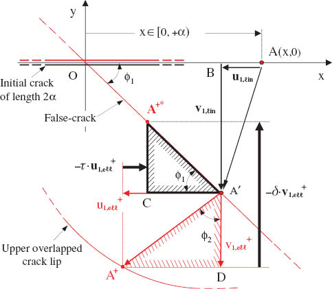
Given that the case of opening cracks was analytically discussed in Ref. [23], only “overlapping” (closing) cracks are considered here. For this case, the successive action of the “linear” and elliptic terms of Eqs. (2) and (3) is schematically depicted in Figure 3 (out of scale for clarity). The double-point A, which initially belongs to both the upper (red and assigned by +) and the lower (assigned by -) crack lips, is displaced according to the linear term to the “double-point” A′ of the false crack. Then, owing to the action of the elliptic term, point A′ splits to two points, A+ and A-, on the upper and the lower lips of the overlapped crack, respectively. In addition, the crack lips slide with respect to each other so that the tips of the overlapped crack do not coincide with the displaced tips, -α′, +α′, of the initial one.

Schematic representation of the overlapping phenomenon of the crack lips (out of scale).
Clearly, for lips in contact (or even more for overlapped lips), the mathematical problem becomes unacceptable from the physical point of view, because overlapping could never occur in practice because of the non-zero thickness of the real disc. In fact, instead of overlapping, the lips of the crack come in contact to each other and contact stresses appear along the lips. Obviously, these stresses cannot be provided from the above solution as the crack lips were initially assumed stress free. (Recall here that analogous problems were met in the solution of the infinite cracked plate [8, 9].) It is emphasized, however, that the above statements do not imply that the solution of the Initial problem [23] has any inherent mathematical mistake. Indeed, given that the crack lips are stress free, the theoretically predicted overlapping is equally well possible as the opening of the crack. This becomes clear considering an extremely thin and flexible cracked medium under an in-plane compression normal to the crack. In this case, even an infinitesimally small force normal to the surface of the medium would lead to overlapping. In other words, although the mathematical overlapping cannot take place in practice, it describes, at least, the deformation tendency of the material.
In any case, it is reasonable to accept that the contact stresses developed in the real problem are somehow related to the overlapping of the mathematical solution. Obviously, if these stresses were known, then by applying them to the mathematical crack, overlapping would be erased and then one would have reached the appropriate first fundamental problem (known stresses both on the disc’s periphery L and also on the crack lips). Unfortunately, these stresses are not a priori known and cannot be estimated by intuition. In this case, the Ariadne thread permitting escape from the dead end is the fact that (contrary to stresses) the displacement field, which could prevent mathematical overlapping, can be determined (it will be proved in next paragraph). Indeed, these displacements are the opposite ones of those that caused overlapping in the Initial problem and are already known. Then, in turn, the contact stresses can be calculated from these displacements through the elastic law adopted.
3 The Brazilian disc with a closing crack
3.1 The Inverse problem
Without loss of generality, it is assumed that in the real case, the final deformed crack is somewhere between its “unnatural” overlapped state and its undeformed position, without overlapping but with its lips under contact stresses. Moreover, it is considered that in the extreme limiting case, the crack lips will have slightly slid relatively to each other in the sense dictated by the external loading. In this context, the actual displacement field for the deformed crack is obtained in terms of a parameter [the number τ, see Eq. (5) below] that, by tracing all its possible values, provides the whole range of the physically acceptable positions of the deformed crack (between its initial and overlapped state) in case overlapping is impending in the Initial problem. This is achieved by superposing on the displacement field obtained in the Initial problem for the overlapped lips an appropriate auxiliary displacement field opposing to overlapping. This field is here considered to consist of both normal and shear (elliptic) components, denoted, respectively, as
where

The confrontation of the overlapping and the physically acceptable deformed crack (out of scale).
It is to be noted that the tips of the deformed crack do not coincide with those of the initial one. New material points, in the neighborhood of -α′, +α′, stand now as the deformed crack tips (Figure 3). Although such a sliding is not likely to be measured in any real material (other than perhaps extremely deformable ones), it describes the deformation tendency.
The values of parameters τ and δ must fulfill the following conditions (analytically obtained in Appendix I):
where
Eq. (5) indicates that for τ=0, δ becomes maximum, implying the maximum possible relative sliding of the two lips (it corresponds to zero friction). On the contrary, for τ=1, δ becomes minimum (δ=1), implying zeroing of the relative sliding of the lips (corresponding to infinite friction or to forces responsible for the sliding of the lips constantly lower than Coulomb’s threshold value for dry friction). In this case, the tip of the initial crack also remains the tip of the deformed crack, and the final deformed crack coincides with the false crack.
From a mathematical point of view, the auxiliary displacement field superimposed to annihilate overlapping is introduced with a mixed fundamental problem called “Inverse”: a disc of radius R with a short central crack of length 2α lies on the complex plane (the origin of the Cartesian reference coincides with the center of the crack aligned with the x-axis); its periphery is stress free, while displacements as well as rotation are assumed to be zero on L. In addition, the auxiliary displacement field is imposed to the crack so that the boundary conditions on the crack lips read as
Index “2” indicates the Inverse problem. This auxiliary displacement field corresponds (as it is thoroughly discussed in Section 4) to contact stresses on the real crack lips. The nature of these stresses and their correspondence to the auxiliary displacement field are presented in Figure 5. Actually, in Figure 5B, the

Schematic representation of the generation of contact stresses (out of scale).
3.2 The complex potentials for the Inverse problem
Introducing Eq. (6) in the familiar formula for displacements in terms of the complex potentials [25]
the following equation is obtained on the crack lips:
Addition and subtraction of Eq. (8), in conjunction to Eqs. (2), (3), and (6), yields
where
Using the two-valued function
whence it follows that [κφ2(z)-ω2(z)]/Xo(z) is holomorphic everywhere on the disc. Assuming that [κφ2(z)-i2(z)]/Xo(z) vanishes on L (in view of the supposition, the small central crack does not influence the disc periphery) dictates that
at any point on the disc. Introducing Eq. (13) in Eq. (10) and solving for φ2(z) yield
where a holomorphic function is omitted from the right hand side of Eq. (14) as φ2(z) is to vanish on L and the integral of Eq. (14) becomes zero on L because of the short crack assumption [see Eq. (15) below for z on L against a small α]. Combining Eqs. (2), (3), (11), and (14), one obtains
where Bk, k=1, 2, 3, 4 are complex constants defined as
Differentiating φ2(z) and ω2(z), Φ2(z) and ω2(z) are obtained, respectively, as
where Dk, k=1,2,3,4 are complex constants defined as
3.3 The General problem
By superposing the solutions of the Initial and the Inverse problems, one obtains the solution of the so-called General problem (also a mixed fundamental problem), which is physically acceptable even for the case of closing cracks. In this general case, the displacement field along the crack lips reads as
or by using Eqs. (2) and (3)
The expressions referring to the General problem carry no indices. The boundary conditions on L are obviously those of the Initial problem. When overlapping is impending in the Initial problem (for specific combinations of the loading angles ϕo, ωo), by ascribing proper values to τ and δ [according to Eq. (5)], then Eqs. (20) and (21) do provide a physically acceptable deformed crack without overlapping (Figure 4). When overlapping is not impending in the Initial problem, then by setting τ and δ equal to zero, Eqs. (20) and (21) are just reduced to Eqs. (2) and (3) of the Initial problem, which in that case provide a rather natural solution.
The complex potentials Φ(z) and Ω(z) for the General problem are easily obtained by the summations Φ(z)=Φ1(z)+Φ2(z) and Ω(z)=Ω1(z)+Ω2(z) of the corresponding formulae of Eqs. (1) and (17). In turn, introducing these, Φ(z) and Ω(z), in the familiar formulae [25]:
the stress field is obtained in closed form for any point of the disc. However, owing to the lengthiness of the respective expressions, only the stresses along the direction of the crack and normal to it (i.e., along the x- and y-axis) are given in Appendix II, for any arbitrary crack inclination (angle ϕo) with respect to the loading axis. Concerning the stresses along x-axis, a distinction is made between the crack lips and the remaining portion of the axis.
4 The contact stresses and the parasitic stress field
The determination of the contact stresses, developed on the lips of closing Griffith cracks, is also a crucial and still open problem. It is mentioned that Eqs. (II.1) and (II.3), given in Appendix II, concerning normal and shear stresses along the lips of the crack, do not provide exactly the contact stresses, as it might be expected, at least for the present problem. In fact, only a portion of them represents the contact stresses because Eqs. (II.1) and (II.3) were obtained by imposing a kind of an “unnatural” displacement field on the crack lips, namely the auxiliary displacement field introduced in the Inverse problem.
To make this obscure point clear, consider the ϕo=90° case. The Initial problem yields for the displacements of the crack lips

The development of parasitic stresses (out of scale).
As it is seen from Eq. (23),
Proceeding in a similar way, it is proved that in the general case (i.e., arbitrary values of ϕo), parasitic stresses are detected in both the normal [Eq. (II.1)] and the shear [Eq. (II.3)] stress components, obtained as
Therefore, one should subtract these parasitic stresses, Eqs. (25) and (26), from the stresses given by Eqs. (II.1) and (II.2) to obtain the actual contact stresses developed on the crack lips, as
Before concluding, it is emphasized that according to Eqs. (27) and (28), the contact stresses obtained are not singular at the crack tips.
5 Applications
The formulae for the stress field – along the crack lips [Eqs. (27), (28), and (II.2)], along the x-axis excluding the crack itself [Eqs. (II.4), (II.5), (II.6)], and along the y-axis [Eqs. (II.7), (II.8), (II.9)] – are applied now for some characteristic values of the geometrical parameters of the problem in order for some critical aspects of the present solution to be enlightened. A disc with R=0.05 m is considered with a central crack of length 2α=0.01 m. For the disc’s material, E=3.19 GPa and ν=0.36. Plane strain conditions are assumed. The external load is Pframe=20 kN, and the contact arc is calculated equal to ωo=11.876° [27]. In accordance to Figure 2D–F (where the unnatural overlapping is shown), the values assigned to angle ϕo are equal to 45°, 70°, and 90° to illustrate the method proposed here to cure the problem and determine the naturally accepted stress field in these cases. The value of the parameter τ is chosen equal to τ=0.80 for ϕo=45°, 70° and τ=0 for ϕo=90° resulting, according to Eq. (5), to δ values equal to 1.00506, 1.00084, and 1.000, respectively.
Upon applying the aforementioned formulae, attention should be paid to the values of the arguments of logarithmic terms that appeared regarding the relative position of points
while if z=iy, then
The above-calculated components of the naturally accepted stress field are plotted in Figure 7 for ϕo=45° both along and normally to the crack (i.e., along the x- and y-axis). Concerning the distribution along the crack axis (Figure 7A), it is observed that all three stress components vary smoothly all along the radius of the disc and only as x→α they exhibit strong local fluctuations, while σxx tends to infinite tensile values. Then, for x∈[0, α) and considering the upper crack lip, it is observed that both σyy and σxy are almost constant. On the contrary, σxx decreases smoothly and changes its sign at about the midpoint of the semi-crack length becoming compressive.

The variation of the stress components along the (A) x- and (B) y-axis for the case with ϕo=45°.
The respective distribution along the y-axis (Figure 7B) is smoother for the whole range of y values in the [0, R] interval, and all three stress components are of a negative sign.
The results for ϕo=70°, plotted in Figure 8, are of more or less similar nature and only quantitative differences appear.

The variation of the stress components along the (A) x- and (B) y-axis for the case with ϕo=70°.
In case the crack is normal to the load axis (ϕo=90°), things are different. As expected, the shear component disappears (owing to symmetry), while the distribution of normal stresses resembles closely that predicted by the classic solution for the intact disc [28, 29], assuming that one does not closely approach the crack tips. For x→α (Figure 9A), σxx changes sign, becoming compressive and then at x=α “jumps” abruptly to tensile values remaining almost constant in the [0, α) region equal to about 30 MPa. On the contrary, σyy remains constantly compressive and only a relatively small “jump” is observed at x=α. In the region [0, α), σyy remains again almost constant equal to about -40 MPa. Normally to the crack, the normal stress distribution again resembles that given by Hondros’ solution [28] for the intact disc, the only difference being the fact that as y→0, both stresses start increasing their absolute values instead of remaining constant.

The variation of the stress components along the (A) x- and (B) y-axis for the case with ϕo=90°.
6 Discussion and conclusions
An attempt was presented to confront the so-called “ill-posed” first fundamental problem of linear elasticity for a medium (finite of infinite) with a stress-free crack. As it has been concluded, among others by Markides et al. [23], the stress-free lips of a short central crack in a Brazilian disc appear to overlap each other for a wide range of configurations (i.e., direction of the external loading with respect to the crack axis), rendering in this case the mathematical solution of the Initial problem unnatural. Indeed, overlapping can never occur in practice. Actually, instead of overlapping, the lips of the real crack come in contact and contact stresses are developed along them, which cannot be provided by the mathematical solution of the Initial problem. It was mentioned, however, that apart from overlapping, the Initial first fundamental problem is rather natural. Starting from this point, it was clearly stated in the present study that the solution of the Initial problem in the case of overlapping is not inherently mathematically wrong, and therefore could be proven useful. Actually, overlapping is the deformation tendency of the material and obviously somehow proportional to the real contact stresses. On the basis of this statement, it was made possible to eliminate overlapping and construct a physically acceptable mixed fundamental problem, the General one, which is capable to provide also the contact stresses on the crack lips.
The solution of the General problem was restricted to the determination of the displacements only along the crack lips and also of the stresses along both the x-axis (including the crack itself) and the y-axis (normal to the crack). The expressions for stresses and displacements at an arbitrary point z in the disc, although can be obtained in a similar manner, are omitted here only owing to their lengthiness.
Given that the most important application of the cracked Brazilian disc configuration is the determination of the SIFs, it is worth mentioning that according to the present solution, the SIFs appear to depend (although slightly and indirectly) on the material properties of the disc and the jaw. Indeed, formal application of the standard definition of SIFs (as it can be found in any standard “fracture mechanics” textbook) yields the following expressions (recalling again that the crack is assumed relatively small with respect to the radius of the disc, i.e., ρ=α/R<0.25):
where Pframe=2pRωot is the overall external force applied on the disc. Clearly, the factors FI and FII do depend on the materials’ properties (as angle ωo is directly related to the relative stiffness of the disc’s material with respect to that of the jaw). Therefore, the SIFs-load relations are not linear. This can be clearly seen in Figure 10 where the dependence of KI is plotted versus the externally applied load for a disc made from PMMA with R=0.05 m, t=0.01 m, ϕo=0°, and two ρ-values equal to 0.1 and 0.2.

The mode I SIF for a disc made of PMMA with ϕo=0°. The deviation from linearity (dotted lines) is clear for both crack lengths considered. The square and rhomboid symbols correspond to the values experimentally obtained with the aid of the reflected caustics technique.
Obviously, the above material dependence of the SIFs is due to the fact that the SIFs are commonly defined for the first fundamental problem configuration. The specific definition, if formally applied also for the mixed fundamental problem, is “responsible” for the above-mentioned (peculiar at a first glance) dependence. It is thus imperative to reconsider the concept of SIF in case the crack lips come in contact, to relieve the SIFs obtained for closing cracks from their material properties dependence, as it is proposed, for example, by Markides et al. [30].
Another point that should be carefully considered is related to the assumption that the axis of the final deformed crack is identical to that of the false crack. That choice was made as the displacements due to the “linear” term (responsible for the appearance of the false crack) do not contradict to the physical sense, while those due to the elliptic one (causing overlapping) do. Clearly, one could have chosen as a final naturally acceptable deformed crack another configuration in between its undeformed and overlapped states, different from that having the direction of the false crack. Namely, one could have considered a more complicated auxiliary displacement field that could have an “inverse” effect also to the “linear” term of the displacements, i.e., by reducing the rigid body rotation and the lengthening or shortening of the crack, or even more by admitting a curved final deformed crack rather than a straight one. Such an alternative auxiliary displacement field (of the crack lips) would be perhaps more natural and possibly closer to reality and could solve the problem related to the generation of the parasitic stresses. However, in that case, the mathematical procedure would be much lengthier and complicated, while the improvement (compared with the present solution) is questionable and in any case marginal.
In any case and in spite of the above-mentioned limitations, preliminary experimental data obtained from an ongoing research project [31], implemented with the aid of the method of reflected caustics [32], support the theoretical analysis. This is clearly seen in Figure 10 where the experimental data are plotted in juxtaposition to those of the analytic solution. The agreement is rather satisfactory, at least for load levels that do not approach the fracture one, i.e., as long as the linearity assumption adopted in the theoretical analysis is not violated.
In concluding this section, it is pointed out that, as discussed in Section 1, it will be interesting to revisit this problem by employing the gradient elasticity theory of LEFM. It is noted, in this connection, that the initial contributions in the field [15–19] have recently been supplemented with new results and robust non-singular solutions for crack tips as discussed by Aifantis and coworkers [33–37].
Acknowledgments
This research is co-financed by the EU (European Social Fund-ESF) and Greek national funds through the Operational Program “Education and Lifelong Learning” of the National Strategic Reference Framework (NSRF) -Research Funding Program: THALES: Reinforcement of the interdisciplinary and/or inter-institutional research and innovation. Discussions with Professor E.C. Aifantis are also kindly acknowledged.
Appendix I: The relation between τ and δ
Considering (in accordance to Figure 4) the (OA′B) triangle, it is obtained that (Figure A1)
The relation between τ and δ.
for any point of the crack and ϕ1 the angle the direction of the false crack subtends with the axis of the crack, i.e., the x-axis.
Similarly from the (A+DA′) triangle, shown in Figure A1, it is obtained that
for any point of the crack except its tips, and ϕ2 subtended from vectors of elliptic terms of displacements.
Finally from the (CA′A+*) triangle, it holds that
Combining Eqs. (I.2) and (I.3) and solving for δ, one takes
where ϕ1 and ϕ2 are given by Eqs. (I.1) and (I.2).
Appendix II: The stress field on the disc
II.1a Stresses along the x-axis on the lips of the crack
In this case, using Eq. (22) and letting z to tend to x∈(-α, +α) from the upper and the lower side of the crack, the stress field on the lips of the crack is obtained as
II.1b Stresses along thex-axis (excluding the crack lips)
II.2 Stresses along the y-axis
References
[1] Burniston EE. Int. J. Fract. Mech. 1969, 5, 17–24.Search in Google Scholar
[2] Tweed J. Int. J. Eng. Sci. 1970, 8, 793–803.Search in Google Scholar
[3] Thresher RW, Smith FW. Int. J. Fract. 1973, 9, 33–41.Search in Google Scholar
[4] Burniston EE, Gurley WQ. Int. J. Fract. 1973, 9, 9–19.Search in Google Scholar
[5] Aksogan O. Int. J. Fract. 1975, 11, 659–670.Search in Google Scholar
[6] Bowie OL, Freese CE. Eng. Fract. Mech. 1976, 8, 373–379.Search in Google Scholar
[7] Dundurs J, Comninou M. Int. J. Eng. Sci. 1983, 21, 223–230.Search in Google Scholar
[8] Theocaris PS, Pazis DN, Konstantellos BD. Int. J. Fract. 1986, 30, 135–153.Search in Google Scholar
[9] Pazis DN, Theocaris PS, Konstantellos BD. Int. J. Fract. 1988, 37, 303–319.Search in Google Scholar
[10] Theocaris PS, Sakellariou M. Eng. Fract. Mech. 1991, 38, 231–240.Search in Google Scholar
[11] Beghini M, Bertini L. Eng. Fract. Mech. 1996, 54, 667–678.Search in Google Scholar
[12] Corrado M, Carpinteri A, Paggi M, Mancini G. In: Walraven JC, Stoelhorst D, Eds. Tailor Made Concrete Structures – New Solutions for Our Society. CRC Press/Balkema, The Netherlands, 2008, pp. 541–546.Search in Google Scholar
[13] Carpinteri A, Corrado M, Paggi M. Int. J. Fract. 2010, 161, 161–173.Search in Google Scholar
[14] Chen YZ, Lin XY, Wang ZX. Int. J. Comp. Methods 2008, 5, 119–133.10.1142/S0219876208001418Search in Google Scholar
[15] Exadaktylos G, Vardoulakis I, Aifantis E. Int. J. Fract. 1996, 79, 107–119.Search in Google Scholar
[16] Aifantis EC. Int. J. Eng. Sci. 1992, 30, 1279–1299.Search in Google Scholar
[17] Altan BS, Aifantis EC. Scrip. Metal. Mater. 1992, 1, 319–324.Search in Google Scholar
[18] Ru CQ, Aifantis EC. Acta Mech. 1993, 101, 59–68.Search in Google Scholar
[19] Aifantis EC. J. Mech. Behav. Mater. 1994, 5, 355–375.Search in Google Scholar
[20] Theocaris PS, Sakellariou M. Acta Mech. 1990, 85, 55–70.Search in Google Scholar
[21] Fowell RJ, Xu C. Int. J. Rock Mech. Min. Sci. Geomech. Abstr. 1994, 31, 571–579.Search in Google Scholar
[22] Jia Z, Castro-Montero A, Shah SP. Cement Concrete Res. 1996, 26, 125–137.Search in Google Scholar
[23] Markides ChF, Pazis DN, Kourkoulis SK. J. Eng. Math. 2013, 83, 143–168.Search in Google Scholar
[24] Kolosov GV. Application of the Complex Variable to the Theory of Elasticity (in Russian). ONT1, Moscow-Leningrad, 1935.Search in Google Scholar
[25] Muskhelishvili NI. Some Basic Problems of the Mathematical Theory of Elasticity. P. Noordhoff, Groningen, 1963.Search in Google Scholar
[26] Pazis DN, Agioutantis Z, Kourkoulis SK. Strain 2011, 47, 489–498.10.1111/j.1475-1305.2009.00714.xSearch in Google Scholar
[27] Markides ChF, Kourkoulis SK. Rock Mech. Rock Eng. 2012, 45, 145–158.Search in Google Scholar
[28] Hondros G. Aust. J. Appl. Sci. 1959, 10, 243–268.Search in Google Scholar
[29] Markides ChF, Pazis DN, Kourkoulis SK. Int. J. Rock Mech. Miner. Sci. 2010, 47, 227–237.Search in Google Scholar
[30] Markides ChF, Pazis DN, Kourkoulis SK. Appl. Math. Model. 2011, 35, 5636–5651.Search in Google Scholar
[31] Kourkoulis SK. In: Proceedings of the 30th Danubia-Adria Symposium on Advances in Experimental Mechanics, Alfirevic I, Damir S, Eds. (Primosten, Croatia, 25–28 September 2013). Croatian Society of Mechanics, Zagreb, Croatia, 2013, pp. 13–14.Search in Google Scholar
[32] Theocaris PS. J. Appl. Mech. 1970, 37, 409–415.Search in Google Scholar
[33] Aifantis EC. Int. J. Eng. Sci. 2009, 47, 1089–1099.Search in Google Scholar
[34] Aifantis EC. Int. J. Eng. Sci. 2011, 49, 1357–1367.Search in Google Scholar
[35] Aifantis EC. J. Mech. Behav. Mater. 2011, 20, 103–105.Search in Google Scholar
[36] Konstantopoulos I, Aifantis EC. J. Mech. Behav. Mater. 2013, 22, 193–201.Search in Google Scholar
[37] Askes H, Aifantis EC. Int. J. Solids Struct. 2011, 48, 1962–1990.Search in Google Scholar
©2014 by De Gruyter
This article is distributed under the terms of the Creative Commons Attribution Non-Commercial License, which permits unrestricted non-commercial use, distribution, and reproduction in any medium, provided the original work is properly cited.
Articles in the same Issue
- Frontmatter
- Distributed non-singular dislocation technique for cracks in strain gradient elasticity
- The centrally cracked Brazilian disc: implications and solutions in case of closing cracks
- A statistical study of precursor activity in rain-induced landslides
- Analysis of the effect of gravity and nonhomogeneity on Rayleigh waves in higher-order elastic-viscoelastic half-space
- Experimental study on the mechanical behavior and microstructural assessment of Kevlar/epoxy composites at liquid nitrogen temperature
- Strain hardening exponents and strength coefficients for aeroengine isotropic metallic materials – a reverse engineering approach
- A note on gradient thermoelasticity
- Nonlocal vibration of a carbon nanotube embedded in an elastic medium due to moving nanoparticle analyzed by modified Timoshenko beam theory-parametric excitation and spectral response