Challenges and Present Fields of Action at Laser Scanner Based Deformation Analyses
-
Christoph Holst
 and
Heiner Kuhlmann
and
Heiner Kuhlmann

Abstract
Due to improved laser scanning technology, laser scanner based deformation analyses are presently widespread. These deformation analyses are no longer based on individual points representing the deformation of an object at selected positions. Instead, they are based on a large number of scan points sampling the whole object. This fact either leads to challenges regarding metrological aspects as well as regarding modeling aspects:
Estimating and quantifying spatial correlations between scan points and incorporating them into the deformation analysis
Separating the laser scanners’ internal systematic errors from areal deformations
Minimizing the bias at areal deformation analyses due to a worse network configuration and limited object knowledge
Developing freeform parameterizations to reproduce arbitrary areal deformations of an object by individual parameters
Incorporating an extended uncertainty model considering also model errors due to imperfect knowledge and simplification of the sampled object.
Only when considering all of these aspects, laser scanner based deformation analyses can benefit from the potential of the areal object sampling. This study aims at naming and reasoning these aspects. Furthermore, it introduces first methodologies and approaches for dealing with them.
1 Introduction
Since several years, the field of engineering geodesy has been subject to change. This is due to the fact that engineering geodesy generally attends to applied problem statements [22]. Based on these aspects, especially the areal acquisition of objects and their geometries – up to an integrated space continualization ([11], pp. 653) – got into focus of engineering geodesy. Examples are the areal deformation analyses of dams [5, 37] or radio telescopes [12, 33], the growth analysis of plants [4, 9] and the kinematic mapping based on multi-sensor-systems [7, 10]. This development is mainly based on two progresses:
Laser scanning metrology: scanning 1 million points per second with a 3D point accuracy of several millimeters at mid-range applications has become reality.
Commercial software: processing of laser scans has become more user-friendly and more efficiently so that even large point clouds can be analyzed and parameterized without being a laser scanner specialist.
Both aspects and other continuous enhancements spread the use of laser scanners even outside of research institutions. Hence, the fields of application for laser scanners can be assumed to become even more manifold in the future.
Consequently, objects are no longer sampled and discretized by a small number of individually defined signalized points. Instead, they are area-wise sampled by a large number of non-signalized points whose individual positions cannot be set up. This opens, on the one hand, new opportunities since objects are sampled nearly continuously in space. On the other hand, it contradicts the procedure of carefully setting-up the number and position of sampling points representing the object. This procedure, which is based on balancing either accuracy as well as cost effectiveness, has been established in engineering geodesy for decades by the name of network design [11]. This fact makes completely new demands regarding the subsequent data processing ([11], pp. 653): Up to now, deformation analyses are focused on analyzing single points or point differences to decide whether the sampled object is deformed at selected positions. Since there are no longer signalized points when using laser scanners and, thus, also no longer identical points between two epochs, judging an object to be deformed can only be based on an areal parameterization. This fact directly leads to several challenges:
Challenge 1: The configuration of the parameter adjustment for deformation analysis is no longer set up by the geodetic engineer when defining the number and position of the sampling points but by the laser scanner that samples the surface circularly. Only the station of the laser scanner and the sampling density can be controlled (see Section 3.3).
Challenge 2: A surface parameterization is quested that is able to detect and parameterize deformations that are unknown and, thus, possibly spread along the whole surface (see Section 3.4).
Challenge 3: Due to the inclusion of a surface parameterization, an extended error model needs to be included. This incorporates metrological as well as model errors that arise out of imperfect knowledge and simplification of the object (see Section 3.5).
These challenges are all model based. Additionally, some metrological aspects need to be handled for using laser scanners even for high accuracy deformation analyses:
Challenge 4: Laser scanner measurements are correlated. Consequently, methods for estimating, quantifying and incorporating these correlations need to be investigated (see Section 3.2).
Challenge 5: Laser scanners suffer from internal, systematic errors leading to systematic effects in the point cloud. These effects can hardly be isolated from the areal deformations that are of interest. Thus, strategies for calibrating laser scanners should be developed (see Section 3.1).
All of these challenges that are very relevant for laser scanner based deformation analyses are considered in the present paper (see Section 3). Before, Section 2 gives an overview about the basics of laser scanner based deformation analyses.
While this paper does not claim to solve all of these challenges, it rather aims at naming and reasoning relevant fields of action that need to be handled in the future. First methodologies and approaches are also presented.
2 Basics of Laser Scanner Based Deformation Analyses
General considerations about terrestrial laser scanning for deformation analyses and several examples are given by, e. g., Eling [5] or Wang [37]. In the present paper, only some specific aspects are depicted. The current section groups laser scanner based deformation analyses by the type of deformation, the type of reference surface and the type of surface representation. Since the deformation analysis of natural objects, e. g., landslides, also got into focus of engineering geodesy, the following statements are related each time to deformation analyses of man-made structures and natural surfaces, respectively.
2.1 Type of Deformation
Generally, deformations describe either geometrical changes in shape and dimension, i. e., relative movements inside the object’s surface, as well as rigid body movements ([11], pp. 92; [3]). Analyzing the first category of deformations is more common at laser scanner based deformation analyses since a laser scanner is perfectly suited to acquire surfaces, their geometries and potential changes in geometry nearly continuously in space.
To analyze rigid body movements, collecting the deformation of some selected object points representing the complete rigid object is sufficient usually. Hence, if an object is assumed to move only as a rigid body, laser scanners are used only seldom for deformation analysis.
Consequently, not the position and orientation of the scanned surface is of main interest at most laser scanner applications, but inner geometrical changes of the surface itself due to relative movements. This increases the demands on a suited surface representation being able to detect even small geometrical, inner deformations.
This differentiation between rigid body movements and relative movements inside the object’s surface is straightforward when analyzing the deformations of man-made structures. However, this is not the case when dealing with natural phenomena. E. g., judging whether a landslide only moves (rigid body movement) or also changes its shape and dimension (relative movement) is not a trivial task. This is, amongst others, based on the fact that natural phenomena cannot be distinguished from the environment easily as, e. g., a man-made dam can.
2.2 Type of Reference Surface
At the first type of reference surface, the deformation analysis is based on one single epoch. Here, areal deformations of the surface are defined as deviations from a given reference surface where the parameter values of this surface can either be also given or their estimation is part of the deformation analysis. Examples are the deformation analysis of a cooling tower with given hyperbolic parameterization [17] or the deformation analysis of the main reflector of a radio telescope with a given paraboloid parameterization [15].
In the second scenario, surfaces are scanned in at least two epochs: deformations equal deviations between the surfaces of different epochs. Hence, the reference surface is not given but has been determined in a previous epoch. For the deformation analysis of a dam, see Alba et al. [1] or Eling [5].
When analyzing the deformation of man-made structures, a combination of both scenarios is usually performed: Since the surface is constructed, it follows certain physical rules like smoothness or straightness that are known priori due to construction plans. Consequently, reference parameterizations might exist.
Contrary, when analyzing natural surfaces, e. g., like landslides, rocks or solifluction processes – where no reference parameterization can be given due to lack of knowledge –, two or more epochs are needed to discover deformations.
2.3 Type of Surface Representation
To compare the scanned point cloud to a reference surface or to the surface of a previous epoch, a surface representation is needed. Dependent on the choice of surface representation and the aim of the deformation analysis, the comparison is point-based, point cloud-based, surface-based, geometry-based or parameter-based [29].
Either the complexity of the underlying representation as well as the expressiveness increases from the first type to the latter one: While the point- and point cloud-based approaches do not consider any surface or other connection between neighbouring points of a surface, the surface-based approach only connects neighbouring points by a mesh or other parameter-free representations. Hence, all sorts of measurement errors degrade the outcome of these three types of surface representations.
Only at the geometry- and parameter-based approach, the surface is represented based on parameters and an adjustment. While the geometry-based approach only analyzes areal deviations from the reference, the parameter-based approach explicitly analyzes the estimated parameters. Examples for each representation can be found in Ohlmann-Lauber and Schäfer [29] and Kuhlmann and Holst [21].
Similar to Section 2.1 and 2.2, a division between man-made structures and natural surfaces is appropriate: Man-made structures can, usually, more easily be parameterized than natural surfaces. Thus, natural surfaces are often represented only point-, point cloud- or surface-based. Since these approaches are not based on an adjustment, the spatial point distribution and the measurement noise directly impact the quality of the deformation analysis. This problem is also addressed in Dupuis et al. [4] for the deformation analysis of leafs.
3 Challenges at Laser Scanner Based Deformation Analyses
As stated in the Introduction, several challenges need to be considered when analyzing areal deformations based on terrestrial laser scans. These challenges are theoretically derived, reasoned and applied to laser scanner based deformation analyses in the subsequent sections 3.1–3.5.
3.1 Calibration of Laser Scanners
The technology of laser scanning has not yet been subjected to a quality management as is had been done for other geodetic instruments like levels, total stations or GPS-antennas. The complexity of performing a quality assessment of a terrestrial laser scanner arises out of the fact that laser scanners appear as a black-box [36]: their internal error sources and the pre-processing steps of the measurements are hidden from the operator.
A panoramic laser scanner is constructed by three main axes (Figure 1), i. e., primary and secondary rotation axes and collimation axis. The first and second one are similar to the trunnion axis and the vertical axis, respectively, of a total station. The collimation axis is defined by the laser beam vector after reflection at the mirror.
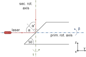
Internal construction of a panoramic terrestrial laser scanner.
For scanning, a laser beam generated by a diode is aligned to the center of a mirror whose reflecting surface is inclined to the laser beam axis by 50 gon. The primary rotation axis is defined by the longitudinal axis of this mirror whose rotation around this axis leads to the vertical deflection β of the laser beam. Due to this parallelism of laser beam vector and primary rotation axis, the laser beam is deflected by an angle of 100 gon following the equality of incidence angle α and emergent angle α’. This whole construction rotates around the secondary rotation axis that deflects the laser beam horizontally by the angle t. Similar to the construction of a total station, the three axes – i. e., primary rotation axis, secondary rotation axis, collimation axis – are assumed to be orthogonal to each other and to coincide in one point.
All of these physical assumptions can only be met to a certain level of accuracy. Hence, deviations from these assumptions lead to systematic measurement errors. These can be grouped in four categories [16]:
Laser: horizontal and vertical eccentricities, horizontal and vertical inorthogonalities, etc.
Mirror: inclination error, etc.
Axes: vertical index error, horizontal and vertical eccentricities of secondary rotation axis, horizontal and vertical inorthogonalities of primary rotation axis, etc.
Electrooptical distance measurement: zero error, scale factor, etc.
While the first three groups of error sources are due to misconstruction of the deflection unit, the latter one describes errors of the distance measurements. As indicated in the enumeration, the list of error sources is not exhaustive [16].
Figure 2 exemplarily shows the effect of the inclination error of the mirror: Due to the error of Δφ, the laser beam vector is deflected by an error of 2 ⋅ Δφ leading to errors in the horizontal direction. For the scanning of a plane in 10 m distance, the resulting systematic error of the horizontal angle t when simulating an inclination error of Δφ = 2.5 mgon is shown in Figure 3.
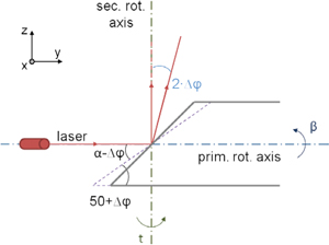
Effect on the beam deflection due to a inclination error of the mirror Δφ.
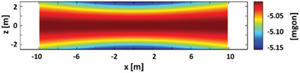
Error of horizontal angle t due to an inclination error of the mirror of Δφ = 2.5 mgon when scanning a plane in 10 m distance where the laser scanner is stationed symmetrically in front of the plane.
As can be seen, this error is not negligible. This especially holds for areal deformation analyses since these systematic measurement errors need to be isolated from the areal deformations. Otherwise, it is hardly possible to distinguish between deformation and measurement errors. However, this isolation is a hard task as both, the areal deformations and also the measurements errors, lead to areal deviations from the reference surface.
The isolation of the systematic errors during the regular deformation analyses only succeeds in exceptional applications, e. g, at the deformation analysis of the 100 m radio telescope in Effelberg, Germany [14, 15]. However, this isolation only worked since the deformed object was sampled in two faces, the object covered nearly the whole field of vision of the laser scanner and the object is known very accurately [14].
These matters of fact explain the necessity of calibrating a laser scanner before using it for deformation analyses. This calibration of terrestrial laser scanners is based on two steps:
Defining the calibration parameters that have to be estimated and assessing of the corresponding equations. These differ partially from the ones of a total station, as has already been shown by the previous categorization and the view in the inside of a panoramic laser scanner (see Figures 2–3).
Developing a calibration field that can be used to estimate the calibration parameters with high accuracy and low correlation.
Both steps are presently fields of action at research institutions, which can be seen by the great amount of publications where only a short selection can be named here: Gordon [6], Holst und Kuhlmann [14], Holst et al. [16], Lichti et al. [25], Reshetyuk [31], Rietdorf [32]. For further discussion, see Kuhlmann and Holst [21].
3.2 Spatial Correlations of Scan Points
The stochastic model of terrestrial laser scans is often limited to assuming variances for the measured polar elements: horizontal angle, vertical angle and distance. Correlations either between these polar elements of one scan point as well as the ones between the polar elements of different points are neglected. This fact is reasoned by the lack of knowledge about the correlations. However, it represents the reality only insufficiently which can be specified in the following.
When sampling an object by a terrestrial laser scanner, four error sources degrade the accuracy of the scan points: the internal errors due to misconstruction (see Subsection 3.1), the measurement configuration (i. e., incidence angle; [38]), metrological conditions and the object itself [35, 39]. While the first category affects all measured polar elements of a laser scanner, the other ones affect only the electro-optical distance measurements. The error sources of each category lead to stochastic (random) as well as to deterministic (systematic) errors that can only be identified and eliminated to a certain amount. This especially holds for the object errors that are mainly due to the material of the object, its color and reflectivity.
The systematic errors being not eliminated correlate the measurements as they are not normally-distributed. Since most of these errors only vary slowly along the surface of the measured object (i. e., the ones due to similar angles of impact, object characteristics and metrological conditions), one can assume the correlation to be proportional to the distance between scan points. Hence, neighbored points are correlated very high whereas the correlation converges to zero with increasing point distance.
However, neither the correlations’ magnitude nor their spatial decrease is known. Hence, by neglecting these correlations in the stochastic model of the deformation analysis, the estimated covariances are far too optimistic. Consequently, parameters and corresponding areal deformations are assumed to be significant because it is implied by the high parameter accuracy [13, 14].
This can be emphasized by simulations: A plane is scanned in 10 m distance where the measured distances are correlated between neighbored scan points. In real applications, this correlation would not be known. Hence, the covariance matrix would only consider variances of the polar elements. The global test of the approximation [26] is declined in this case. Contrary, if the correlation between the scan points had been known and, thus, had been integrated in the stochastic model, the global test would have been accepted.
In the first case, this global test, thus, indicates that observations, functional and stochastic model are not consistent. Since the observations are simulated, the decline of this global test can be reasoned by the neglect of correlations in the stochastic model. However, when performing real scans, this discovered inconsistency in the approximation could most probably not be related directly to the neglected spatial correlations of the scan points. Hence, due to the lack of information about spatial correlations, the non-deformed plane might be assumed to be deformed.
While the existence of correlations could have been proven in some studies [18, 19] general strategies for revealing and assessing correlations are not at hand. This is challenging since these correlations presumably differ by a large amount between different measurement configurations and object properties.
Thus, estimating and including spatial correlations of scan points is a present field of action at laser scanner based deformation analyses. Prospective studies could focus on determining the effective number of measurements ([11], pp. 346) and the correlation structure dependent on different configurations and object properties. Similar investigations also helped to improve the stochastic model of the GPS [20].
3.3 Configuration of Surface Approximation
When approximating a scanned surface, the number of observations is usually sufficient regarding redundancy to estimate the surface parameters. The large number of scan points implies high accuracy and reliability of the derived results. However, both accuracy and reliability rather depend also on the regularity of the object sampling. At laser scanning, this object sampling is irregular due to the polar deflection.
Holst [12] and Holst and Kuhlmann [14] show that the network configuration of the surface approximation is a better indicator – compared to the absolute redundancy – for certifying the quality of the results of the surface approximation. For analyzing the network configuration, they use the partial redundancies combining functional model, stochastic model and sampling density. In this analysis, they reveal the large impact of the regularity of the object sampling. Here, not the absolute number of scan points is of interest but their spatial distribution.
At areal deformation analyses, the surface is not known completely. Instead, the surface may be affected by local, unknown deformations leading to arbitrary areal deviations from the reference surface. Their detection and quantification is one aim of the corresponding areal deformation analyses of the object. Consequently, the object knowledge – resulting in the associated surface parameterization – is only limited (see Section 3.5).
At laser scanner based deformation analyses, both aspects are combined: the sampling density is irregular and the object knowledge is incomplete. This results in a biased parameter estimation. Holst and Kuhlmann [14], Holst et al. [13, 15] and Holst [12] revealed these biases for different kinds of deformation analyses by investigating the network configuration. A reduction of this bias and its variation that depend on the station of the laser scanner can be obtained by (1) thinning the point cloud to a regular sampling, by (2) inserting spatial correlations between neighboring points or by (3) robust estimation [13]. However, each of these solutions bears disadvantages since (1) scan points are eliminated, (2) nearly completely filled covariance matrices need to be processed or (3) different kind of error models are used for approximation.
Hence, handling the irregular sampling in combination with the limited object knowledge is a present field of action for laser scanner based deformation analyses [12].
3.4 Surface Parameterization
The Introduction addresses the continualization of engineering geodesy which also strengthens the need of transforming point-wise methods used in deformation analyses to areal methods. This consideration can be highlighted by two selected aspects presented in the following.
3.4.1 Parameter-based Freeform Surfaces
Section 2.3 discusses several types of surface representations. Here, only the parameter-based approach relates the estimated parameters directly to geometric deformations. This has been done at, e. g., the deformation analysis of the Effelsberg radio telescope [15]. However, the use of parameter-based approaches is presently restricted to deformation analyses of objects that can be parameterized by geometric primitives or other simple geometric forms.
At more complex objects, freeform surfaces like NURBS [30] or radial basis functions [2] would need to be used for approximation. This especially holds for natural objects as, e. g., leafs: Dupuis et al. [4] compare a mesh based approach to a spline based approach at parameterizing leafs. The results attest the spline based approach significantly better accuracy and reliability. Harmening and Neuner [9] additionally show the possibility of parameterizing more complex leafs by NURBS.
However, NURBS do not yet permit to relate individual parameters to individual areal deformations. Right now, there is no possibility to interpret these surface parameters so that they could be used for a parameter test in deformation analyses. Hence, these parameterizations are only used in surface-based approaches right now.
Consequently, strategies for building freeform surfaces based on parameters that can directly be related to specific areal deformations are needed. Only then, parameter-based deformation analyses are not restricted anymore to simple geometric forms like main reflectors of radio telescopes.
3.4.2 Inclusion of Stochastic Signal
The results of the surface approximation and, hence, of the areal deformation analysis, depend by a high degree on the priori selected surface representation. The corresponding surface parameters are defined in the functional model of approximation. Contrary, the stochastic model influences the deformation analysis by a fewer amount. This fact is advantageous right now since the stochastic model is not yet known close to reality (see Subsection 3.2): only variances are incorporated, correlations between scan points are neglected.
However, due to correlations and systematic errors of the measurements, the surface representation should also allow the stochastic model to be forming. This is relevant since stochastic aspects that are not normally-distributed can build up surfaces that appear to be deterministic as well: e. g., correlations between scan points can lead to local deviations from the reference surface similar to real deformations.
A proper inclusion of the stochastic model could be done by estimating a stochastic signal within the surface approximation, similar to a collocation [27]. Then, this stochastic signal being defined by its autocovariance function would optimally parameterize all correlations while the remaining deviations equal the areal deformations.
Hence, these considerations are directly helpful for areal deformation analyses: true deformations could be isolated from areal deviations resulting from correlations or a missing calibration of the laser scanner, respectively. As already mentioned, all of these deviations from the reference surface could appear similar. Following, the inclusion of a stochastic signal is a relevant field of action at laser scanner based deformation analyses. First considerations about this topic are also raised in Harmening and Neuner [8, 9].
3.5 Extended Uncertainty
At surface approximations, the functional model of the object, i. e., the surface parameterization, has to be defined priori. Thus, object knowledge has to be integrated. At some approaches, this object knowledge is given explicitly, e. g., at the deformation analysis of the main reflector of the 100 m radio telescope in Effelsberg: The main reflector equals a rotational paraboloid. Contrary, when approximating, e. g., a church’s vault or leafs [9], the object knowledge is only limited.
Independent from this general question whether the geometry of the object is known priori or is easy to parametrize, the object can only seldom be parameterized accurately. Hence, the surface parameterization is afflicted with uncertainty. However, previous studies about laser scanner based deformation analyses only consider metrological aspects affecting the uncertainty (see also Subsection 3.1–3.2). Consequently, these considerations should be extended by the object uncertainty leading to an extended uncertainty model. Extended uncertainty models have already been proposed by Kutterer [23, 24], Schön [34] and Neumann [28].
The metrological uncertainty arises out of deterministic and stochastic errors (see Section 3.1–3.2). Contrary, the object uncertainty arises out of imperfect knowledge and simplification: Imperfect knowledge describes the imprecise knowledge about the real object, simplification the generalized surface parameterization. The first aspect includes unknown deformations, the latter one object details being neglected in the surface parameterization.
Both types of object uncertainty affect the parameter estimation systematically and, thus, bias the deformation analysis (see also Section 3.3). While this bias cannot be reduced by including an extended uncertainty model, the inclusion of the object uncertainty would lead to more realistic parameter variances so that this bias would not be significant any more. Hence, an extended uncertainty model would save from misleadingly detected deformations.
Integrating an extended uncertainty model would be feasible within an interval approach [23, 34] or within the fuzzy-theory [28] which could both be used instead of least-squares estimation.
Altogether, these considerations need to be focused in future studies. An integration of object uncertainty seems to be unavoidable to deal with either limited object knowledge as well as with realistic estimates of the parameters’ uncertainties.
Only if this succeeds, a significant parameter test for detecting and analyzing areal deformations can be performed. Hence, the integration of an extended uncertainty model is a present field of action at laser scanner based deformation analyses.
4 Conclusion and Outlook
The present paper introduces, motivates and discusses several fields of action at laser scanner based deformation analyses. All of these aspects are new challenges at geodetic deformation analyses since the transformation from point-wise methods and tools to areal ones has not been performed sufficiently until now. Hence, this study mentions several methodical challenges that represent the model based fields of action at laser scanner based deformation analyses.
Furthermore, the quality assessment of point clouds derived from terrestrial laser scanners needs to be improved. Only then, it is possible to isolate internal systematic laser scanner errors and unavoidable correlations between scan points from true areal deformations. These corresponding mentioned challenges are, thus, metrological based fields of action.
While some of these challenges have already been mentioned in previous studies as listed in the corresponding sections, the present paper connects them for the first time which can be highlighted by two examples:
The need of an extended uncertainty model is highly correlated with the configuration of the approximation and the type of surface parameterization.
When using non-calibrated laser scanners at deformation analyses with limited object knowledge, integrating a stochastic signal in the surface approximation properly should improve the parameter estimation.
In the end, laser scanner based deformation analyses can only exhaust their potential due to the nearly continuous object sampling if all of these challenges are solved satisfactorily. The task of solving these challenges as indicated in this study is, at once, the outlook to future work.
References
[1] Alba, M., Fregnese, L., Prandi, F., Scaioni, M., Valgoi, P., (2006). Structural monitoring of a large dam by terrestrial lasre scanning. Int. Arch. Photogramm. Remote Sens. Spat. Inf. Sci. 36 (5).Search in Google Scholar
[2] Buhmann, M. D., (2003). Radial Basis Functions: Theory and Implementations. Cambridge University Press, UK.10.1017/CBO9780511543241Search in Google Scholar
[3] Chrzanowski, A., Frodge, S. L., Avella, S., (1993). The worldwide status of monitoring and analysis of dam deformations. In: Proceedings of 7th International Symposium on Deformation Measurements together with 6th Canadian Symposium on Mining Surveying, Banff, Alberta, pp. 77–88.Search in Google Scholar
[4] Dupuis, J., Holst, C., Kuhlmann, H., (2016). Laser scanner based growth analysis of plants as a new challenge for deformation monitoring. 3rd Joint International Symposium on Deformation Monitoring, Vienna.Search in Google Scholar
[5] Eling, D., (2009). Terrestrisches Laserscanning für die Bauwerksüberwachung. PhD thesis, Wissenschaftliche Arbeiten der Fachrichtung Geodäsie und Geoinformatik der Leibniz Universität Hannover, No. 282.Search in Google Scholar
[6] Gordon, B., (2008). Zur Bestimmung von Messunsicherheiten terrestrischer Laserscanner. PhD thesis, Fachbereich Bauingenieurwesen und Geodäsie der Technischen Universität Darmstadt, D 17.Search in Google Scholar
[7] Gräfe, G., (2007). High precision kinematic surveying with laser scanners. J. Appl. Geodesy, 1 (4), pp. 185–199.10.1515/jag.2007.021Search in Google Scholar
[8] Harmening, C., Neuner, H., (2014). Raumkontinuierliche Modellierung mit Freiformflächen. In: Schriftenreihe DVW, Band 78: Terrestrisches Laserscanning 2014 (TLS 2014), pp. 105–122, Wißner.Search in Google Scholar
[9] Harmening, C., Neuner, H., (2015). Continuous modelling of point clouds by means of freeform surfaces. Vermessung & Geoinformation 2 + 3 / 2015, pp. 121–129.Search in Google Scholar
[10] Hesse, C., (2007). Hochauflösende kinematische Objekterfassung mit terrestrischen Laserscannern, PhD thesis, DGK (German Geodetic Commission), C 608.Search in Google Scholar
[11] Heunecke, O., Kuhlmann, H., Welsch, W., Eichhorn, A., Neuner, H., (2013). Auswertung geodätischer Überwachungsmessungen. In: Möser, Müller, Schlemmer (Eds.): Handbuch Ingenieurgeodäsie, 2nd edition, Wichmann, Heidelberg.Search in Google Scholar
[12] Holst, C., (2015). Analyse der Konfiguration bei der Approximation ungleichmäßig abgetasteter Oberflächen auf Basis von Nivellements und terrestrischen Laserscans. PhD thesis, Universitäts- und Landesbibliothek Bonn.Search in Google Scholar
[13] Holst, C., Artz, T., Kuhlmann, H., (2014). Biased and unbiased estimates based on laser scans of surfaces with unknown deformations. J. Appl. Geodesy, 8 (3), pp. 169–183.10.1515/jag-2014-0006Search in Google Scholar
[14] Holst, C., Kuhlmann, H., (2014). Aiming at self-calibration of terrestrial laser scanners using only one single object and one single scan. J. Appl. Geodesy 8 (4), pp. 295–310.10.1515/jag-2014-0017Search in Google Scholar
[15] Holst, C., Nothnagel, A., Blome, M., Becker, P., Eichborn, M., Kuhlmann, H., (2015). Improved area-based deformatoin analysis of a radio telescope’s main reflector based on terrestrial laser scanning. J. Appl. Geodesy 9 (1), pp. 1–13.Search in Google Scholar
[16] Holst, C., Tegelbeckers, J., Kuhlmann, H., (2014). Erkennung und Erklärung von systematischen Effekten beim TLS, In: Schriftenreihe DVW, Band 78, „Terrestrisches Laserscanning 2014 (TLS 2014)“, pp. 51–68, Wißner.Search in Google Scholar
[17] Ioannidis, C., Valani, A., Georgopoulos, A., Tsiligiris, E., (2006). 3D model generation for deformation analysis using laser scanning data of a cooling tower. In: 3rd IAG / 12th FIG Symposium, Baden, Germany.Search in Google Scholar
[18] Koch, K. R., Kuhlmann, H., (2009). The impact of correcting measurements of laserscanners on the uncertainty of derived results. Zfv 1, pp. 38–44.Search in Google Scholar
[19] Koch, K. R., Kuhlmann, H., Schuh, W. D., (2010). Approximating covariance matrices estimated in multivariate models by estimating auto- and cross-covariances. J. Geod. 84, pp. 383–397.Search in Google Scholar
[20] Kuhlmann, H., (2003). Kalman-filtering with coloured measurement noise for deformation analysis. In: Proceedings, 11th FIG Symposium on Deformation Measurements Santorini, Greece.Search in Google Scholar
[21] Kuhlmann, H., Holst, C., (2016). Flächenhafte Abtastung mit Laserscanning. In: Handbuch Geodäsie, Band Ingenieurgeodäsie, Springer, about to appear.Search in Google Scholar
[22] Kuhlmann, H., Schwieger, V., Wieser, A., Niemeier, W., (2014). Engineering Geodesy – Definition and core competencies. J. Appl. Geodesy, 4, pp. 237–334.10.1515/jag-2014-0020Search in Google Scholar
[23] Kutterer, H., (1994). Intervallmathematische Behandlung endlicher Unschärfen linearer Ausgleichungsmodelle. PhD thesis, DGK (German Geodetic Commission), C 423.Search in Google Scholar
[24] Kutterer, H., (2002). Zum Umgang mit Ungewissheit in der Geodäsie – Bausteine für eine neue Fehlertheorie -, Habilitation, DGK (German Geodetic Commission), C 553.Search in Google Scholar
[25] Lichti, D., Chow, J., Lahamy, H., (2011). Parameter de-correlation and model-identification in hybrid-style terrestrial laser scanner self-calibration. ISPRS J. Photogramm. 66 (3), pp. 317–326.10.1016/j.isprsjprs.2010.12.001Search in Google Scholar
[26] Mikhail, E. M., Ackermann, F., (1976). Observations and least squares. Dun-Donelly, New York, USA.Search in Google Scholar
[27] Moritz, H., (1978). Least-squares collocation. Reviews of Geophysics, 16 (3), pp. 421–430.10.1029/RG016i003p00421Search in Google Scholar
[28] Neumann, I., (2009). Zur Modellierung eines erweiterten Unsicherheitshaushaltes in Parameterschätzung und Hypothesentests. PhD thesis, DGK (German Geodetic Commission), C 634.Search in Google Scholar
[29] Ohlmann-Lauber, J., Schäfer, T., (2011). Ansätze zur Ableitung von Deformationen aus TLS-Daten. In: Schriftenreihe DVW, Band 66, Terrestrisches Laserscanning – TLS 2011 mit TLS-Challenge, pp. 161–180, Wißner.Search in Google Scholar
[30] Piegl, L., Tiller, W., (1997). The NURBS Book. Springer.10.1007/978-3-642-59223-2Search in Google Scholar
[31] Reshetyuk, Y., (2006). Calibration of terrestrial laser scanners Callidus 1.1, Leica HDS 3000 and Leica HDS 2500. Survey Review, 38 (302), pp. 703–713.Search in Google Scholar
[32] Rietdorf, A., (2005). Automatisierte Auswertung und Kalibrierung von scannenden Messsystemen mit tachymetrischem Messprinzip. PhD thesis, DGK (German Geodetic Commission), C 582.Search in Google Scholar
[33] Sarti, P., Vittuari, L., Abbondanza, C, (2009). Laser Scanner and Terrestrial Surveying Applied to Gravitational Deformation Monitoring of Large VLBI Telescopes’ Primary Reflector, J. Surv. Eng., 139 (4), pp. 136–148.10.1061/(ASCE)SU.1943-5428.0000008Search in Google Scholar
[34] Schön, S., (2003). Analyse und Optimierung geodätischer Messanordnungen unter besonderer Berücksichtigung des Intervallansatzes. PhD thesis, DGK (German Geodetic Commission), C 567.Search in Google Scholar
[35] Soudarissanane, S., Lindenbergh, R., Menenti, M., Teunissen, P., (2011). Scanning geometry: influencing factor on the quality of terrestrial laser scanning points. ISPRS J. Photogramm., 66, pp. 389–399.10.1016/j.isprsjprs.2011.01.005Search in Google Scholar
[36] Walser, B., Gordon, B., (2013). Der Laserscanner, eine Black-Box?. In: Schriftenreihe DVW, Band 72, Terrestrisches Laserscanning 2013 (TLS 2013), pp. 149–164, Wißner.Search in Google Scholar
[37] Wang, J., (2013). Towards deformation monitoring with terrestrial laser scanning based on external calibration and feature matching methods. PhD thesis, Wissenschaftliche Arbeiten der Fachrichtung Geodäsie und Geoinformatik der Leibniz Universität Hannover, No. 308.Search in Google Scholar
[38] Zámečniková, M., Neuner, H., Pegritz, S., Sonnleitner, R., (2015). Investigation on the influence of the incidence angle on the reflectorless distance measurement of a terrestrial laser scanner. Vermessung & Geoinformation, 2 + 3 / 2015, pp. 208–218.Search in Google Scholar
[39] Zogg, H., (2008) Investigations of high precision terrestrial laser scanning with emphasis on the development of a robust close-range 3D-laser scanning system. PhD thesis, Institut für Geodäsie und Photogrammetrie an der Eidgenössischen Technischen Hochschule Zürich, Mitteilungen Nr. 98.Search in Google Scholar
© 2016 Walter de Gruyter GmbH, Berlin/Munich/Boston
Articles in the same Issue
- Frontmatter
- Editorial
- Editorial to the Special Edition on Deformation Monitoring
- Research Articles
- Time Series Analysis of 3D Coordinates Using Nonstochastic Observations
- Challenges and Present Fields of Action at Laser Scanner Based Deformation Analyses
- Robust Spatial Approximation of Laser Scanner Point Clouds by Means of Free-form Curve Approaches in Deformation Analysis
- Laser Scanning Based Growth Analysis of Plants as a New Challenge for Deformation Monitoring
- Potential of GPS Common Clock Single-differences for Deformation Monitoring
- Investigations on the Influence of Antenna Near-field Effects and Satellite Obstruction on the Uncertainty of GNSS-based Distance Measurements
- Deformation Measurement of a Driven Pile Using Distributed Fibre-optic Sensing
- Measurement of Deflection in Concrete Beams During Fatigue Loading Test Using the Microsoft Kinect 2.0
- Design and Implementation of a Modern Automatic Deformation Monitoring System
- Deck and Cable Dynamic Testing of a Single-span Bridge Using Radar Interferometry and Videometry Measurements