Investigation on rotor jet interference in a hydraulic reaction turbine for low head low flow water conditions

Abstract
The focus of this paper is to investigate the issue of water jet interference, which is a common flaw in simple reaction turbines. When the turbine’s wall crosses the water jet coming from another nozzle, this is known as jet interference. The governing equations are also used to analyse the Z-Blade simple water reaction turbine for an ideal and practical example, based on the principles of mass-, impulses and energy conservation. Various evaluations of real and potential operating losses for low-head (3–5 m) and low-flow (3 L/s and below) water resources have been conducted. According to experimental data, the Z-Blade turbine Type B achieves the maximum rotational speeds at 450 rpm, followed by Type A at 400 rpm and Type C at 300 rpm. By performing parametric analysis via governing equations, the calculated non-interference speed is approximately twice that of the turbine’s maximum speed. Furthermore, as the turbine reaches its maximum rotational speed at the optimal length diameter, the turbine speed decreases without interference from the jet nozzle rotor. This resembles a phenomenon of non-interference rotor jet on Z-Blade turbine.
Introduction
Pico hydro power is a small-scale development of green energy that uses water to generate less than 5 kW of electricity (ÇElo and Bualoti 2020; Farriz Basar et al. 2010; Kadier et al. 2018). Among the turbine technologies used for pico hydropower generation worldwide is the reaction-type water turbine (Rais and Basar 2021; Mohd, Hambali, and Kamaruzzaman 2013). The gardening water sprinkler as shown in Figure 1 is one of the simplest examples of a reaction water turbine that illustrates its working principle (Date, Date, and Akbarzadeh 2012a; Farriz et al. 2015). In reaction turbine, liquid is pressurised, and it flows through the guiding mechanism to rotate the moving blades or moving nozzle (Basar et al. 2021; Musa et al. 2015). The pressure is reduced when the water glides through the moving blades and the velocity of the water flow in relation to the moving elements is increased (Basar et al. 2011; Date et al. 2012b).

Actual whirling sprinkler.
The pressure not only comes from the potential energy but also from the centrifugal head attributed to the self-pumping effect during turbine rotation (Date and Akbarzadeh 2010).
This investigation was inspired by Abhijit Date’s proposed cross-pipe turbine (CPT) and split-reaction turbine (SRT). The CPT and SRT are both categorized as simple reaction pico-hydro turbines (Date et al. 2013), but only the latter is capable of operating under low-head conditions (Basar 2019). The Z-Blade turbine is presently considered suitable for conditions in small streams. Consequently, under 5 m water height and extremely small flow conditions (to 3.0 L/s) the Z-Blade prototype was tested. While the potential energy available in small streams is less than in a traditional water dam but with a proper turbine design, there can be significant energy efficiencies extracted from the pico hydro. This situation led this research to focus on the design of the turbines so that a practical approach could be developed to small pico-hydro streams.
In addition, the work explores the performance characteristics of the Z-Blade turbine for various nominal diameters of PVC pipes used for the turbine under ideal and practical conditions. The optimum turbine diameter and the maximum rotational speed at different water head levels are then predicted and discussed. This research also proves that the Z-Blade water turbine (ZBT) is a non-interference rotor jet.
Reaction water type turbine
This simple reaction turbine is called “Z-Blade” because it looks like Z’s consonant on its rotor blades. Based on the performance of the ZBT, it is very economically feasible because, although it only requires a small investment, this turbine is still capable of achieving a reasonably higher power output (in the range of 70–100 W) in ultra low water head condition. In addition, the ZBT is believed to be capable of overcoming constraints regarding the depletion of the quantity of water due to drought.
It is the features of the ZBT that can easily change the nozzle exit area. Figure 2 shows the turbine designed by Z-Blade to have a nominal PVC pipe diameter, S, 25 mm (1"). In this study, three types of ZBT were used; Type A (nozzle diameter 0.01 m), Type B (nozzle diameter 0.008 m), and Type C (nozzle diameter 0.006 m).

Rotor stationary reference time.
There are four main components to this turbine: (a) two arms constructed of PVC threaded male adjusters and PVC pipe of different lengths; (b) two elbows of 90° PVC; (c) two end caps of PVC; (d) one central T-joint tube. Interestingly, no water jet nozzles are fixed at both the CPT exit, and the water stream jet is produced by drilling a small hole as a nozzles on the PVC end cap.
Water test rig
The performance of the Z-Blade turbine was assessed using the test apparatus indicated in Figure 3. A polypropylene water tank is supported by a 6 m metal tower. Water from the polypropylene tank can also reach the Z-Blade turbine through the top. The test equipment can produce up to 5 m of water head height and 3 L/s of water flow. Because floating material clogs hydrokinetic turbines in many waterways (Hasim, Basar, and Aras 2011; Yaakub et al. 2018), a filtration device is placed into the test bed to keep debris out of the turbine. The setup was designed to imitate standard pico hydro conditions. The Z-Blade turbine was put through its paces with the generator at the bottom and water at the top.
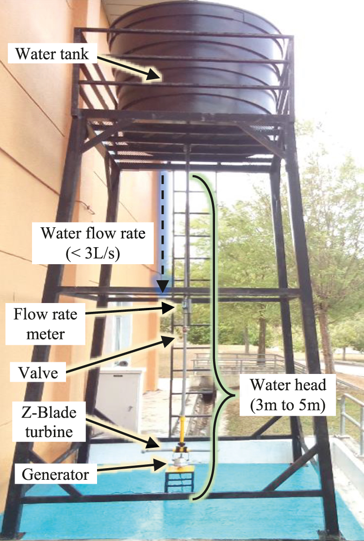
Water test rig.
Figure 3 shows that the gravitational potential energy in the water tank is completely utilised. As a result, this experimental structure is ready for installation on a river (run-off river) or stream bank (a run-on river). On-site, river water will be used to fill the water tank. The turbine nozzle discharges water into the river. The Z-Blade turbine produces a mechanical force that causes the rotor to rotate counter clockwise in relation to the water jet. A generator converts this mechanical force into electrical energy, which is then utilised to power an electrical load.
Governing equations
Z-Blade turbine performance is predicted using the governing equations developed according to the principle of mass, momentum, and energy conservation (Date, Date, and Akbarzadeh 2012a). Figure 4 relates to the diagrams which show the rotor radius, nozzle, and velocities.
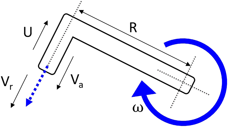
Schematic showing the parameter of Z-Blade turbine.
Mass flow rate,
Therefore,
When the turbine is stationary, ω = 0, the mass flow rate is,
By rewriting Eq. (5), the angular speed for the rotor can be calculated,
The turbine produces mechanical output power,
The efficiency of the system that can transform potential energy into output power can be described as,
Performance of Z-Blade turbine
The total results obtained from repeated experimental works were determined to be consistent. The best parameters that most influenced total turbine performance was apparently determined and discussed based on actual and expected data. The dotted line in Figures 5–7 show the experimental performance of the ZBT gathered from the laboratory work shows a similar pattern with the theoretical parametric characteristic analysis, except for a slight reduction in magnitude. These figures illustrate the connection between ZBT rotational speed, water flow rate and blade length in a three-axis diagram. Furthermore, these figures show the performance of Type A, Type B and Type C of ZBT when the water head is set at 4 m.

Experiment and theoretical results for Type A at 4 m static head.
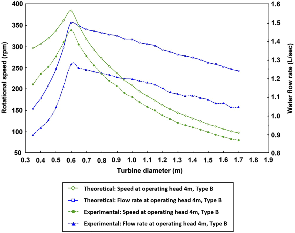
Experiment and theoretical results for Type B at 4 m static head.

Experiment and theoretical results for Type C at 4 m static head.
Based on experimentation and parametric analysis via the governing equations, the optimum length (diameter) of the ZBT can be identified by referring to the peak of the bell-shaped lines. These lines are obtained when the angular speed is plotted against the length of the turbine (diameter) with the constant operating head. The optimal diameter is defined as the maximum rotational speed for a given water head corresponding to the length (diameter). The important thing to note is that ZBT reached the highest rotational velocity at this unique (optimal) turbine diameter for any water head level, pipe size and nozzle exit area. It is worth noting that, based on Figures 5–7, the optimum diameter is determined at the moment when the rotational speed, centrifugal head, Hc relative velocity, Vr and the mass flow rate, ṁ decreases significantly.
Initially, the theoretical and experimental findings for the short turbine diameter show a large speed disparity. However, when the turbine diameter increases, both speed curves approach each other. The smaller radius of the turbine can have a substantial impact on the rise in speed. The rotational speed of the short turbine diameter is highly sensitive to changes in mass flow rate. The higher the radius of the turbine, the slower the speed.
It is worth noting that the important parameters presented in the theoretical and experimental curves in Figures 4–6 must be discovered. Important parameters including static water head, water flow rate, ideal turbine diameter, and maximum rotational speed will be used to study and verify whether the water turbine is experiencing the interference rotor jet phenomenon during operation. The effort to mathematically prove this phenomenon will be discussed in detail in the next section.
Phenomenon of non-interference water jet
During the experimental work, jet interference – a common disadvantage of a simple turbine reaction type – did not happen in the ZBT. After attaining the maximum rotational speed at the optimum diameter without encountering jet nozzle rotor interference, the ZBT’s turbine speed declines. This results in a rotating speed turbine with no interference. In contrast, the angular speed of the SRT and CPT will increase until the jet nozzle interference speed occurs (Basar 2019).
SRT and CPT must cope with the phenomenon of jet interference (Date and Akbarzadeh 2010). Jet interference is a phenomenon occurring when the wall of the turbine breaks the jet of water from another nozzle. As a result, due to the force of the water jet the turbine pushes in the opposite direction to make the turbine rotate above its non-interference rotational speed. It then causes a reduction and disturbance to the angular speed, absolute velocity, and net torque produced (Rais and Basar 2021). For a constant water head, this phenomenon sets the limitation speed that can be reached by SRT and CPT, thus limiting the power output capacity.
Referring to Figure 8, the equation for the non-interference speed of the ZBT can be derived in the condition where time FE, tFE (point F to point E) equals to time GE, tGE (point G to point E).
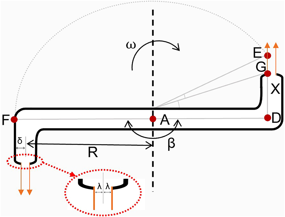
Non-interference parameters of ZBT.
Assuming that tFE = tGE, by customizing the theoretical analysis of jet-interference of simple reaction turbine proposed by (Date and Akbarzadeh 2010), we obtain the following relationship:
From the geometry shown in Figure 7, we get
and
By substituting Eqs. (13) and (14) into (12), we obtain,
By substituting Eqs. (11) and (16) into (10), the non-interference speed is derived as,
Combining Eqs. (2), (7) and (17), we have
When the value β (which means the angle between the two consecutive nozzles) decreases, the non-interference speed is reduced. This results in more frequent turbine rotation interruptions as the number of the nozzles increases. Furthermore, the speed of non-interference will decrease if the width of the water jet nozzles increases as shown in Tables 1–3.
Non-interference speed of ZBT for Type A.
| Parameter | Type A | ||
|---|---|---|---|
| Head (m) | 5 | 4 | 3 |
| Mass flow rate (kg/s) | 3.12 | 2.31 | 1.69 |
| Radius (m) | 0.35 | 0.3 | 0.25 |
| m/ρA | 19.5 | 14.4 | 10.5 |
|
|
0.136 | 0.127 | 0.116 |
|
|
0.377 | 0.405 | 0.442 |
|
|
45.0 | 53.1 | 66.1 |
| Non-interference speed (rpm) | 1078 | 1505 | 2084 |
| Theoretical speed (rpm) | 498 | 374 | 277 |
| Experimental speed (rpm) | 419 | 310 | 248 |
Non-interference speed of ZBT for Type B.
| Parameter | Type B | ||
|---|---|---|---|
| Head (m) | 5 | 4 | 3 |
| Mass flow rate (kg/s) | 2.09 | 1.5 | 1.1 |
| Radius (m) | 0.35 | 0.3 | 0.25 |
| m/ρA | 20.9 | 15.0 | 11.0 |
|
|
0.134 | 0.124 | 0.114 |
|
|
0.369 | 0.397 | 0.433 |
|
|
47.1 | 55.8 | 70.0 |
| Non-interference speed (rpm) | 1119 | 1544 | 2059 |
| Theoretical speed (rpm) | 502 | 385 | 305 |
| Experimental speed (rpm) | 450 | 339 | 270 |
Non-interference speed of ZBT for Type C.
| Parameter | Type C | ||
|---|---|---|---|
| Head (m) | 5 | 4 | 3 |
| Mass flow rate (kg/s) | 1.19 | 0.83 | 0.6 |
| Radius (m) | 0.35 | 0.3 | 0.25 |
| m/ρA | 21.1 | 14.7 | 10.6 |
|
|
0.131 | 0.122 | 0.111 |
|
|
0.362 | 0.389 | 0.424 |
|
|
49.4 | 58.8 | 74.5 |
| Non-interference speed (rpm) | 1184 | 1685 | 2133 |
| Theoretical speed (rpm) | 500 | 368 | 278 |
| Experimental speed (rpm) | 446 | 315 | 240 |
Table 1 shows the non-interference rotational speed, theoretical speed and experimental speed of ZBT using Eqs. (7) and (18). All the value shows in Table 1 is determined using the ZBT that has been fabricated using pipes with nominal diameter Ø0.025 m: 1 inch. It has two arms with the parameters β = 180 o; δ = 0.021 m; λ = 0.005 m, 0.004, 0.003 m; and GD = X = 0.075 m.
Here, the component
The greatest experimental rotational speed that Type B can attain with 5 m of water head and a turbine diameter of 0.7 m is around 450 rpm, as indicated in Table 1. Using Eq. (18), the calculated non-interference speed is 1119 rpm, which is twice as fast as the theoretical maximum speed (502 rpm) that the ZBT can achieve. In another example, the highest experimental speed that Type A can achieve for a 4 m water head with a turbine diameter of 0.6 m is 310 rpm. Furthermore, the calculated non-interference speed is 1505 rpm, but this is too far off from the theoretical maximum speed that it can accomplish. It is also worth noting that the higher the value of non-interference speed, the lower the water head and turbine diameter are.
The jet interference phenomena should not occur in the ZBT, according to the non-interference rotational speed equation that has been calculated. This innovative turbine is free to spin at its maximum speed, and it has been proven to be consistent over numerous repetitions of the experimental work. As a result, it is not necessary to consider jet-interference when developing this turbine at this time because the ZBT does not experience from the typical drawbacks associated with simple reaction type turbines. In addition, unlike SRT, where a speed damper is used for the control of maximum run-off velocity at both ends of the nozzle [12], no speed damper is required at both ends of the nozzle of the ZBT.
Conclusions
In summary, this paper demonstrates many advantages in both theoretically and experimentally, the Z-Blade turbine, which is a modified concept based on CPT and SRT. This paper therefore presents a reaction-type turbine that is capable of being used in a pico-hydro system, in particular for low-head and low-flow water. The Z-Blade water turbine is used as a mathematical model based on the principle of mass, energy and energy conservation in order to check its performance in incompressible conditions under water.
Jet interference, a common issue of a simple reaction turbine, was not present in the ZBT during testing. The ZBT’s turbine speed reduces after achieving the maximum rotational speed at the optimum diameter without meeting jet nozzle rotor interference. This appears to be a non-interference rotational speed turbine. The SRT and CPT, on the other hand, will rise in angular speed until they approach the jet nozzle interference speed.
The derived non-interference rotational speed equation indicates that the jet interference phenomenon should not occur in the ZBT. This innovative turbine is free to spin at its maximum speed, and it has been found to be consistent over many repetitions of the experimental work. As a result, it is not critical at this time to consider jet interference when designing this turbine because the typical drawbacks experienced by simple reaction type turbines do not occur with the ZBT.
Funding source: Ministry of Higher Education (MOHE) Malaysia
Award Identifier / Grant number: PRGS/1/2014/TK06/FTK/02/T00011
Funding source: Universiti Teknikal Malaysia Melaka http://dx.doi.org/10.13039/501100004768
Award Identifier / Grant number: MTUNC/2019/FTKEE-CERIA/MC0013
-
Author contributions: All the authors have accepted responsibility for the entire content of this submitted manuscript and approved submission.
-
Research funding: Author would like to thank Ministry of Higher Education Malaysia (PRGS/1/2014/TK06/FTK/02/T00011) and Universiti Teknikal Malaysia Melaka (MTUNC/2019/FTKEE-CERIA/MC0013) for providing the laboratory facilities and technical support.
-
Conflict of interest statement: The authors declare no conflicts of interest regarding this article.
References
Basar, M. F., A. Ahmad, N. Hasim, and K. Sopian. 2011. “Introduction to the Pico Hydro Power and the Status of Implementation in Malaysia.” In 2011 IEEE Student Conference on Research and Development, 283–8.10.1109/SCOReD.2011.6148751Search in Google Scholar
Basar, M. F., F. S. Mohd Hassan, N. A. Rais, I. A. Zulkarnain, and W. A. Wan Mustafa. 2021. “Performance Analysis of Z-Blade Reaction Type Turbine for Low-Head Low Flowrate Pico Hydro.” Journal of Advanced Research in Fluid Mechanics and Thermal Sciences 85 (2): 51–65, https://doi.org/10.37934/arfmts.85.2.5165.Search in Google Scholar
Basar, M. F. 2019. “Economic Analysis on Design of a Simple Hydraulic Reaction Type Turbine for Low-Head Low-Flow Pico Hydro.” International Journal of Innovative Technology and Exploring Engineering 9 (2): 3876–980, https://doi.org/10.35940/ijitee.b7257.129219.Search in Google Scholar
ÇElo, M. and R. Bualoti. 2020. “Grid Integration Issues and Possible Solutions Considering the Expansion and Deployment of Hydropower Plants in Albania.” International Review of Economics Education 15 (1): 80, https://doi.org/10.15866/iree.v15i1.16497.Search in Google Scholar
Date, A. and A. Akbarzadeh. 2010. “Design and Analysis of a Split Reaction Water Turbine.” Renewable Energy 35 (9): 1947–55, https://doi.org/10.1016/j.renene.2010.01.023.Search in Google Scholar
Date, A., A. Date, and A. Akbarzadeh. 2012a. “Performance Investigation of a Simple Reaction Water Turbine for Power Generation from Low Head Micro Hydro Resources.” Smart Grid and Renewable Energy 03 (03): 239–45, https://doi.org/10.4236/sgre.2012.33033.Search in Google Scholar
Date, A., A. Date, A. Akbarzadeh, and F. Alam. 2012b. “Examining the Potential of Split Reaction Water Turbine for Ultra-low Head Hydro Resources.” Procedia Engineering 49: 197–204, https://doi.org/10.1016/j.proeng.2012.10.128.Search in Google Scholar
Date, A., A. Date, and A. Akbarzadeh. 2013. “Investigating the Potential for Using a Simple Water Reaction Turbine for Power Production from Low Head Hydro Resources.” Energy Conversion and Management 66: 257–70, https://doi.org/10.1016/j.enconman.2012.09.032.Search in Google Scholar
Farriz, M., H. Boejang, M. Masjuri, M. Aras, N. Razik, S. Mate, and K. Sopian. 2015. “Evolution of Simple Reaction Type Turbines for Pico-Hydro Applications.” Jurnal Teknologi 77 (32), https://doi.org/10.11113/jt.v77.6980.Search in Google Scholar
Farriz Basar, M., A. A. Rahman, A. Din, and Z. Mahmod. 2010. “Design and Development of Green Electricity Generation System Using Ocean Surface Wave.” In Proceedings of the International Conference on Energy and Sustainable Development: Issues and Strategies (ESD 2010), 1–11.10.1109/ESD.2010.5598773Search in Google Scholar
Hasim, N., M. F. Basar, and M. S. Aras. 2011. “Design and Development of a Water Bath Control System: A Virtual Laboratory Environment.” In 2011 IEEE Student Conference on Research and Development, 403–8.10.1109/SCOReD.2011.6148773Search in Google Scholar
Kadier, A., M. S. Kalil, M. Pudukudy, H. A. Hasan, A. Mohamed, and A. A. Hamid. 2018. “Pico Hydropower (PHP) Development in Malaysia: Potential, Present Status, Barriers and Future Perspectives.” Renewable and Sustainable Energy Reviews 81: 2796–805, https://doi.org/10.1016/j.rser.2017.06.084.Search in Google Scholar
Mohd, B. F., B. Hambali, and S. Kamaruzzaman. 2013. “Quran as Inspiration for Implementation of Pico Hydro System.” International Journal of Educational Research 1: 1–10.Search in Google Scholar
Musa Othman, M., J. A. Razak, M. F. Basar, N. S. Muhammad, W. M. F. Wan Mohammad, and K. Sopian. 2015. “A Review of the Pico-Hydro Turbine: Studies on the Propeller Hydro Type.” International Review of Mechanical Engineering (IREME) 9 (6): 527, https://doi.org/10.15866/ireme.v9i6.5876.Search in Google Scholar
Rais, N. A. M. and M. F. Basar. 2021. “Pico-Hydro Generation System: Empirical Investigation on a Novel Z-Blade Low-Head Low-Flow Water Turbine.” International Journal of Renewable Energy Resources 11 (1): 108–13.Search in Google Scholar
Yaakub, M. F., M. F. Basar, F. H. M. Noh, and H. Boejang. 2018. “Pico-hydro Electrification from Rainwater’s Gravitational Force for Urban Area.” TELKOMNIKA (Telecommunication Computing Electronics and Control) 16 (3): 997, https://doi.org/10.12928/telkomnika.v16i3.8076.Search in Google Scholar
© 2021 Walter de Gruyter GmbH, Berlin/Boston
Articles in the same Issue
- Frontmatter
- Research articles
- A human heartbeat frequencies based 2-DOF piezoelectric energy harvester for pacemaker application
- Development of a new aerofoil profile with a high lift-to-drag ratio for wind turbines using a low fidelity accurate optimization flow solver
- Investigation on rotor jet interference in a hydraulic reaction turbine for low head low flow water conditions
- Performance study and critical review on energy aware routing protocols in mobile sink based WSNs
- Energy capable clustering method for extend the duration of IoT based mobile wireless sensor network with remote nodes