Vibration Modeling of Arc-Based Cantilevers for Energy Harvesting Applications
-
Daniel J. Apo


Abstract
Cantilever beams are widely used for designing transducers for low-frequency vibration energy harvesting. However, in order to keep the dimensions within reasonable constraints, a large tip mass is generally required for reducing the resonance frequency below 100 Hz which has adverse effect on the reliability. This study provides a breakthrough toward realizing low-frequency micro-scale transduction structures. An analytical out-of-plane vibration model for standalone arc-based cantilever beams was developed that includes provisions for shear and rotary inertia, multidirectional arcs, and multiple layers. The model was applied to a multilayered cantilever beam (10-mm wide and 0.1-mm thick) composed of three arcs, and the results indicate that the fundamental bending mode of the beam was 38 Hz for a silicon substrate thickness of 100 μm. The model was validated with modal experimental results from an arc-based cantilever made out of aluminum.
Introduction
The performance, capabilities, and deployment of wireless sensor networks (WSNs) continue to rise. One of the reasons for the rapid proliferation of the WSNs is related to the significant progress being made in CMOS electronics that has brought down the power requirements considerably. At the same time, there has been significant progress in development of energy harvesters that can meet the power requirements of the electronics and enhance the lifetime and limitations of a conventional battery. Among these varieties of energy harvesting approaches, vibration energy harvesting (VEH) has been pursued both as an alternative and as a supplement to batteries, and in recent years there has been a surge in the number of publications in this area. In order for VEH to become practical, the size and weight of the harvester should be compatible with the mm-scale electronics and sensors. Recent study by Mitcheson et al. (2007) has shown that at the mm-scale, piezoelectric mechanism provides the best output power density at low frequencies as compared to other possible mechanisms for VEH. However, piezoelectric-based VEH presents a fundamental challenge at the small dimensions, since the resonance frequency of the structure increases as the dimension decreases. This challenge should be overcome in order for this technology to become compatible with the applications.
Vibration analysis of curved beams has been extensively investigated in literature. Ojalvo (1962) has presented an analysis of coupled twist-bending vibrations of incomplete circular rings by applying the classical Euler–Bernoulli beam theory. A two-span curved girder was modeled by Culver and Oestel (1969) for use in the bridge structures. Some of the early literature in this field has utilized Timoshenko beam theory (Timoshenko 1921) and investigated the effects of transverse shear and rotary inertia on circular beam vibration (Philipson 1956; Rao 1971; Rao and Sundararajan 1969; Seidal and Erdelyi 1964). Rao (1971) have shown that the modeling of circular arc beams without incorporation of both rotary inertia and shear deformation leads to errors in the calculation of natural frequencies. Over the past four decades, there have been other reports that have incorporated the Timoshenko beam theory in modeling of circular arc or ring beams. Wang et al. (Tung-Ming, Laskey, and Ahmad 1984; Wang, Nettleton, and Keita 1980) have studied the out-of-plane vibrations of continuous unidirectional circular beams with and without shear and rotary inertia consideration. Their study provided the detailed development of a dynamic circular beam stiffness matrix. Howson and Jemah (1999) have also studied out-of-plane vibrations of continuous unidirectional circular beams and introduced parameters that can be modified to gauge the effects of shear and rotary inertia. More recently, Lee and Chao (2000) presented the theory for non-uniform circular arc beams with constant radius. However, the exact modeling of continuous circular arc beams which are multilayered and multidirectional has been absent in literature.
Cantilever beams have been used widely in low-frequency energy harvesting applications at the micro-scale (Karami and Inman 2011). However, the increase in natural frequency as cantilevers become smaller limits the low-frequency potential of standalone micro-cantilevers. Several researchers have attempted to resolve this problem by adding a tip mass to the end of the cantilever. However, a more effective method lies in developing uniquely shaped cantilevers, such as arc-based cantilevers, which exhibit low natural frequencies. In this paper, a general out-of-plane vibration model for single and continuous circular arc beams is presented. The effects of bending, torsion, transverse shear deformation, and rotary inertia have been incorporated in the development of the model. The model can be applied for multilayered beams with different beam boundary conditions (e.g. clamped, pinned, and free). To demonstrate the application of model, an example of a multilayered multidirectional continuous beam with three circular arcs is included. The beam was designed for piezoelectric energy harvesting application. To verify the accuracy of the numerical model, experimental results of an arc-based cantilever are compared with numerical results. The theory presented in this paper can be applied to the modeling of micro-scale or macro-scale beams which can be divided into any number of circular arcs (such as S-shaped beams).

Schematic representation of a circular arc beam
Theoretical development of the model
Governing equations
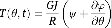
Consider the circular arc beam shown in Figure 1. The expressions for the bending moment,
 , and twist torque,
 , of the beam can be written as (Rao 2007):

where
 is the Young’s modulus,
 is the area moment of inertia in the bending plane,
 is the modulus of rigidity,
 is the polar moment of inertia,
 is the radius,
 is the angle of twist,
 is the slope of the deflection curve when shearing is neglected,
 is the angular coordinate, and
 is the time.
In the presence of shearing force, the slope of the transverse deflection curve is expressed as:

where z is the vertical displacement (deflection) of the beam, and
 is the angle of shear at the neutral axis. We can express the shear force in the transverse direction (
 ) as:
) as:

where
 is the cross-sectional area of the beam and η is the shear coefficient. The parameter
 is an indication of the variation of
 through the cross-section. For rectangular cross-sections,
 can be expressed as (Blevins 1979):
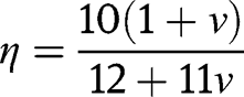
where
 is the Poisson’s ratio. From eqs [3] and [4], we can express
 as:
as:

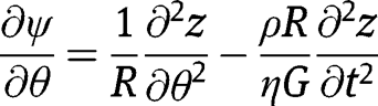
For free vibrations, external force and torque distributions are neglected, and the equations of motion for the rotation of a circular arc about the radial and tangential axes can be written as:
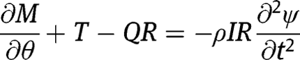

where
 is the mass density of the beam. The equation governing the translation of a differential element of the beam in the transverse direction is given as:

Using input from eqs [1]–[6], eqs [7]–[9] can be re-written as:

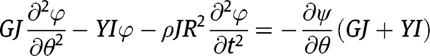
From eqs [10]–[12], we can obtain a single equation of the form:
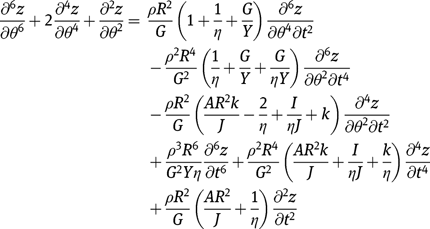
where
 is the stiffness parameter
 . We can assume solutions for the transverse deflection, slope, and twist of the beam as:

where
 is the natural frequency and
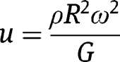
 . Applying the assumed solutions to eqs [11]–[13], we obtain the spatial form of the equations as:

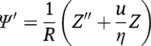

where
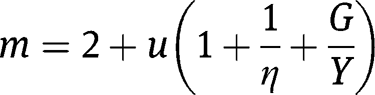
We can further assume spatial solutions of the form:
where the values of
 are numerical constants, and the values of
 are the roots of the characteristic equation:

Plugging the assumed spatial solutions into eq. [15], we obtain the values of
 and
and
 as:
as:
Boundary and continuity matrices
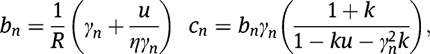
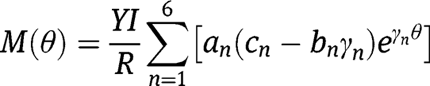
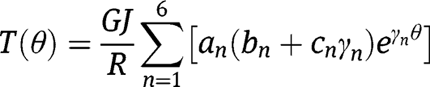
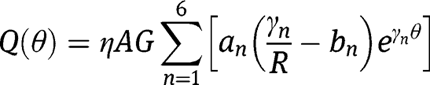
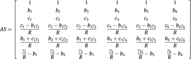
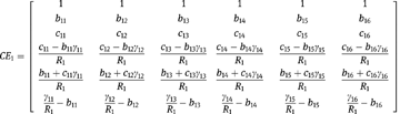
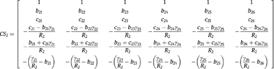
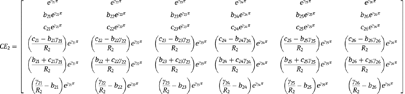
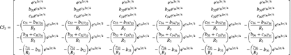
In order to calculate the natural frequencies, we consider six properties. These properties include the deflection, slope, and twist as expressed in eq. [19a–c]. The other three properties are the bending moment (M), twist torque (T), and transverse shear force (Q). They are determined from eqs [1], [2], [6], and [19a–c] and expressed as:
Therefore for any circular arc beam defined with
 in the clockwise direction, we can define the continuity conditions by the beam properties at its ends. We can represent the beam properties at the start of the arc (
 ) in matrix form as:
while the beam properties at the end of the arc (AE) can be written as:
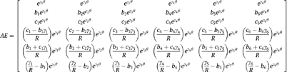
The matrices
 and
and
 serve as the continuity conditions for beams comprising more than one circular arc.
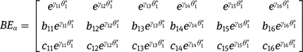
For any circular arc beam or combination of circular arc beams, we can write the known boundary conditions at the two ends,
 , in matrix form. For a beam clamped at one end and free on the other end, and consisting of
 number of circular arcs, the known boundary conditions are (Blevins 1979):


where θ* represents the angular location (0 or θ) on the arc to which the boundary condition is applied. Therefore, we can obtain the boundary condition matrices as:

Natural frequencies and mode shapes
The boundary and continuity conditions described so far result in an eigenvalue problem for continuous beams with circular arcs. To obtain the natural frequencies for a single arc beam, we can write the expression as:

where

and
with known values of beam material properties and geometry for the arc,
 is only dependent on
 . The values of
 which satisfies
 are the natural frequencies of the beam. The numerical constants can be obtained thereafter by setting
 to an arbitrary value and solving for
 to
to
 from eq. [28]. Thereafter, the mode shapes can be obtained by plugging the numerical constants into eq. [19a–c]. For a beam consisting of
 number of arcs, we can write
where
 is a combination of the beam boundary and continuity matrices and
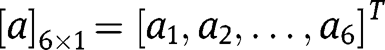
 is a combination of the numerical constants of the circular arcs which can be expressed as:

Again, with known values of beam material properties and geometry for each arc,
 is only dependent on
 Therefore the values of
 which satisfies
 are the natural frequencies of the beam. The numerical constants can be obtained thereafter by setting
 to an arbitrary value and solving for
 to
to
 from eq. [31]. Thereafter, the mode shapes can be obtained by plugging the numerical constants into eq. [19a–c].
In order to reduce numerical errors and time, we can reduce the sizes of matrices in eq. [31]. If
 and
and
 represent the start and end continuity matrices, respectively, of an arc in the direction of the full beam (e.g. clamped end to free end), continuity conditions require that (Karami and Inman 2011):
Note that
 and
and
 are determined by the direction of the whole beam and either of
 and
and
 could therefore occur at
 of the specified arc. Also, the bottom three rows of the
 matrix for each beam must be multiplied by –1 to account for the equilibrium conditions from one arc to the next. The equilibrium conditions are


Therefore, we can write
where

The eigenvalue problem now becomes

where

and
As with matrices
 and
and
 , the values of
 which satisfy
 are the natural frequencies of the beam. Thereafter, the numerical constants for the first arc can be obtained by setting
 to an arbitrary value and solving for
 to
to
 from eq. [37]. The numerical constants for the remaining arcs can then be obtained by applying eq. [33]. The mode shapes can be obtained by plugging the numerical constants into eq. [19a–c].
Effective mechanical properties for multilayered beams
In many applications of micro-cantilever beams, a number of layers of different materials are bonded to each other to provide the desired effect. For multilayered beams with rectangular cross-sections, we can determine approximate effective properties needed for calculating the natural frequencies and mode shapes. The theory presented here is based on the following assumptions:
The beam is in uniform torsion;
The beam layers as well as the composite beam are elastic, homogeneous, and isotropic;
The beam layers are perfectly bonded to prevent in-plane shearing; and
The overall thickness of the composite beam is small compared with its width and length.
The effective properties required for calculating the natural frequencies of circular arc beams are the effective flexural rigidity,
 , the effective shear modulus,
 , the effective mass per unit length,
 , and the effective Poisson’s ratio,
 . Consider the beam cross-section shown in Figure 2(a) where the bottom layer is the thicker of the two layers. The distances from the neutral axis can be expressed as (Erturk and Inman 2008; Timoshenko and Young 1968):

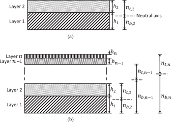
Schematic depiction of multilayered beam cross-sections with the layers arranged in order of decreasing thickness (from bottom to top): (a) cross-section of a beam with two layers and (b) cross-section of a beam with
 layers
where
 represents the distance from the end of the bottom layer to the neutral axis (for 2 layers),
 represents the distance from the top of the top layer to the neutral axis (for 2 layers),
 is the thickness of the bottom layer, and
 is the thickness of the top layer. Therefore, we can write the effective flexural rigidity for a beam with two layers and width
 as:
as:

Now consider a beam with more than two layers. If we rearrange the layers (from bottom to top) in descending order of their thicknesses, we can obtain a well-defined cross-section as shown in Figure 2(b). The effective flexural rigidity for a beam with
 layers can be written as:
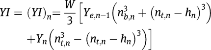
where

and this is solved further until
 . Therefore for
 layers, there are
 flexural rigidity equations to be solved in order to obtain the overall effective flexural rigidity. Note that any term with subscript
 indicates an effective property and not the property of a single layer. For example,
 denotes the effective Young’s modulus for layers 1 to
 while
while
 denotes the Young’s modulus for layer
 only. The effective thickness for
 layers is simply a sum of the thicknesses of all the
 layers, while the effective area moment of inertia for
 layers is calculated assuming the
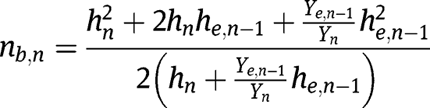
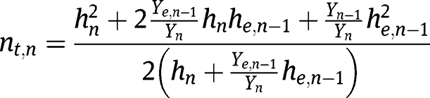
 layers comprise a single beam. We can also write the distances from the neutral axis for any number of layers. For
 layers, the equations for the distance to the neutral axis can be written as:
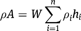
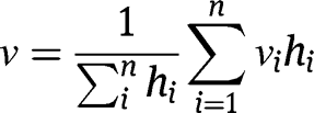
The effective mass per unit length and Poisson’s ratio for a beam with
 layers can be calculated from rule of mixtures and expressed as (respectively):
and
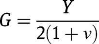
The effective shear modulus,
 , can be obtained from:
Cantilever beam example
Modeling analysis
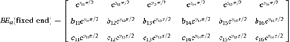
A multilayered cantilever beam with constant cross-section is shown in Figure 3. It is clamped at one end and free at the other. The beam has been designed for piezoelectric energy harvesting. The beam is layered with different materials which have different material properties, and thicknesses are described in Table 1. The boundary condition matrices for the cantilever are


Example of a micro-cantilever beam with three circular arcs: (a) 3D view of the beam and (b) 2D view of the beam showing its dimensions
Properties of the materials used for the micro-cantilever layers
| Material | Layer no. (effective no.)* | Thickness [μm] | Young’s modulus [GPa] | Density [g/cm3] | Poisson’s ratio |
| Pt | 5 (6) | 0.2 | 168 | 21.45 | 0.38 |
| PZT | 4 (2) | 1 | 66 | 7.8 | 0.35 |
| Pt | 5 (5) | 0.2 | 168 | 21.45 | 0.38 |
| TiO2 | 3 (4) | 0.25 | 230 | 4 | 0.27 |
| SiO2 | 2 (3) | 0.5 | 73 | 2.2 | 0.17 |
| Si | 1 (1) | 100–200 | 112 | 2.329 | 0.28 |
The continuity matrices are
The eigenvalue problem for the beam was solved by combining the beam continuity and boundary matrices according to eq. [38] for the values of
 which satisfy
 . The numerical constants for arc 1 were obtained by setting
 to 1 and solving for
 to
to
 from eq. [37]. Thereafter, the numerical constants for arcs 2 and 3 were obtained by applying eq. [33]. The mode shapes were obtained by plugging the numerical constants into eq. [19a–c].
Figure 4 shows the effect of varying the thickness of the silicon substrate layer of the beam on the variable
 for first four modes (also see eq. [15]). The variable
 is useful for determining the effect of arc geometry (e.g. thickness and arc radius) on the natural frequency. When
 is varied as a function of silicon layer thickness, it behaves nonlinearly, and the nonlinearity increases with mode number. The normalized fundamental mode shape of the beam centerline for the beam described in Table 1 and Figure 3 is shown in Figure 5(a) and 5(b). In this case, the silicon layer thickness is 100 μm. The fundamental mode occurs at 38 Hz, and it exhibits dominant bending behavior. The fundamental bending mode is advantageous for applications which rely on uniform cantilever straining such as piezoelectric energy harvesting. The steps required for modeling the multilayered arc-based cantilever beams are summarized in the modeling flow chart in Figure 6.
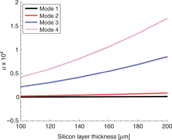
Variation of
 with silicon layer thickness for the arc-based cantilever with three arcs

Mode shape for the fundamental frequency of the micro-cantilever beam: (a) 3D view and (b) side view of showing the displacement profile relative to the clamped end. Blue line = mode shape, black line = undeformed shape

Modeling flow chart for obtaining the natural frequencies and mode shapes of multilayered arc-based cantilever beams
Experimental verification of the numerical model
Modal experimental verification was performed on the cantilever. The geometry of the beam (except thickness) is same as in Figure 3, and it is made up of 0.4064-mm thick aluminum. The experimental setup is shown in Figure 7. The shaker was used to provide a base acceleration to the cantilever which was measured by the accelerometer, while the acceleration of the cantilever was measured by using a laser beam. The peak values of the cantilever acceleration (relative to the shaker acceleration) denote the natural frequencies of the cantilever. The first four modes of the experimental cantilever are shown in Figure 8. It can be seen that the results from the numerical model are in close agreement for the first four modes (<2% error). Euler–Bernoulli equation (Blevins 1979) for a straight cantilever beam with same width (10 mm), thickness (0.4064 mm), and length distance (50 mm) as the experimental cantilever produces 144.27, 902.43, 1,359.6, and 2,533 Hz for the first four modes. Therefore, the straight cantilever exhibits 37–204% increase in natural frequency (from mode 1 to mode 4) when compared with the experimental arc-based cantilever.

Experimental setup for modal analysis of the aluminum cantilever beam

Experimental verification of the numerical model using a single-layer aluminum cantilever: (a) experimental results showing the first four modes of the cantilever and (b) numerical results for the first four modes as a function of beam thickness
Conclusions
A general out-of-plane vibration model for continuous arc-based cantilevers which includes the effects of shear and rotary inertia and also considers the multiple layers of different materials has been developed for the determining the natural frequency and mode shapes. Based on the Timoshenko beam theory, an eigenvalue problem was developed which enables the analysis of multidirectional continuous beams. Expressions for effective properties of multilayered beams were obtained based on calculation of the distances of the layers from the neutral axes and reordering of the layers by decreasing thicknesses. An example cantilever beam was analyzed to illustrate the application of the model and the potential for achieving low-frequency resonance in arc-based beams at the micro-scale. As indicated by the results, the fundamental mode was 38 Hz for 100-μm-thick silicon substrate. The mode shapes showed the behavior of the centerline of the beams and indicated that the important fundamental mode exhibited a dominant bending behavior which is favorable for many micro-scale applications. Modal experiments were performed on an aluminum arc-based cantilever, and the results showed close agreement with the numerical model.
Acknowledgment
The authors acknowledge the financial support from the National Science Foundation (NSF) through the INAMM program (S.P.) and through the ARMDEC (D.A.).
Nomenclature
- θ
-
angular beam coordinate
- t
-
time
- M(θ, t)
-
bending moment
- T(θ, t)
-
twist torque
- Y
-
Young’s modulus
- I
-
area moment of inertia in the bending plane
- R
-
arc radius
- G
-
modulus of rigidity
- J
-
polar moment of inertia
- φ(θ, t)
-
angle of twist
- ψ(θ, t)
-
slope of the deflection curve in the absence of shear
- Z(θ, t)
-
vertical displacement(deflection)
- α
-
angle of shear at the neutral axis
- Q(θ, t)
-
shear force
- A
-
beam cross-sectional area
- η
-
shear coefficient
- ρ
-
mass density
- k
-
stiffness parameter (GJ/YI)
- ω
-
natural frequency
- j
-
imaginary unit (
 )
) - n
-
distance from neutral axis
- h
-
beam/layer thickness
- W
-
beam width
References
Blevins, R. D . 1979. Formulas for Natural Frequency and Mode Shape. New York: Van Nostrand Reinhold.Search in Google Scholar
Culver, C. G. , and D. J.Oestel. 1969. “Natural Frequencies of Multispan Curved Beams.” Journal Sound and Vibration10(3):380–89. doi: 10.1016/0022-460x(69)90216-8.Search in Google Scholar
Erturk, A. , and D. J.Inman. 2008. “A Distributed Parameter Electromechanical Model for Cantilevered Piezoelectric Energy Harvesters.” Journal Vibration and Acoustics130(4):41002–15.10.1115/1.2890402Search in Google Scholar
Howson, W. , and A.Jemah. 1999. “Exact Out-of-Plane Natural Frequencies of Curved Timoshenko Beams.” Journal of Engineering Mechanics125(1):19–25. doi: 10.1061/(ASCE)0733-9399(1999)125:1(19).Search in Google Scholar
Karami, M. A. , and D. J.Inman. 2011. “Analytical Modeling and Experimental Verification of the Vibrations of the Zigzag Microstructure for Energy Harvesting.” Journal of Vibration and Acoustics133(1):11002–10.10.1115/1.4002783Search in Google Scholar
Lee, S. Y. , and J. C.Chao. 2000. “Out-of-Plane Vibrations of Curved Non-Uniform Beams of Constant Radius.” Journal of Sound and Vibration238(3):443–58. doi: 10.1006/jsvi.2000.3084.Search in Google Scholar
Mitcheson, P. D. , E. K.Reilly, T.Toh, P. K.Wright, and E. M.Yeatman. 2007. “Performance Limits of the Three MEMS Inertial Energy Generator Transduction Types.” Journal of Micromechanics and Microengineering17(9):S211.10.1088/0960-1317/17/9/S01Search in Google Scholar
Ojalvo, I. U . 1962. “Coupled Twist-Bending Vibrations of Incomplete Elastic Rings.” International Journal of Mechanical Sciences4(1):53–72. doi: 10.1016/0020-7403(62)90006-1.Search in Google Scholar
Philipson, L. L . 1956. “On the Role of Extension in the Flexural Vibrations of Rings.” Journal of Applied Mechanics23:364–66.10.1115/1.4011337Search in Google Scholar
Rao, S. S . 1971. “Effects of Transverse Shear and Rotatory Inertia on the Coupled Twist-Bending Vibrations of Circular Rings.” Journal OF Sound and Vibration16(4):551–66. doi: 10.1016/0022-460x(71)90662-6.Search in Google Scholar
Rao, S. S . 2007. Vibration of Continuous Systems. Hoboken, NJ: Wiley.Search in Google Scholar
Rao, S. S. , and V.Sundararajan. 1969. “In-Plane Flexural Vibrations of Circular Rings.” Journal of Applied Mechanics36(3):620–25.10.1115/1.3564726Search in Google Scholar
Seidal, B. S. , and E. A.Erdelyi. 1964. “On the Vibrations of a Thick Ring in Its Own Plane.” Journal of Engineering for Industry86:240–44.10.1115/1.3670524Search in Google Scholar
Timoshenko, S . 1921. “On the Correction Factor for Shear of the Differential Equation for Transverse Vibrations of Prismatic Bars.” Philosophical Magazine41:744–46.Search in Google Scholar
Timoshenko, S. , and D. H.Young. 1968. Elements of Strength of Materials. Princeton, NJ: Van Nostrand.Search in Google Scholar
Tung-Ming, W. , A. J.Laskey, and M. F.Ahmad. 1984. “Natural Frequencies for Out-of-Plane Vibrations of Continuous Curved Beams Considering Shear and Rotary Inertia.” International Journal of Solids and Structures20(3):257–65. doi: 10.1016/0020-7683(84)90037-4.Search in Google Scholar
Wang, T. M. , R. H.Nettleton, and B.Keita. 1980. “Natural Frequencies for Out-of-Plane Vibrations of Continuous Curved Beams.” Journal of Sound and Vibration68(3):427–36. doi: 10.1016/0022-460x(80)90397-1.Search in Google Scholar
©2014 by De Gruyter
Articles in the same Issue
- Frontmatter
- Editorial
- Magneto-Mechano-Electric (MME) Energy Harvesting Properties of Piezoelectric Macro-fiber Composite/Ni Magnetoelectric Generator
- Miniature Shape Memory Alloy Heat Engine for Powering Wireless Sensor Nodes
- Comparative Study of Energy Harvesting from ZnO Nanorods Using Different Flexible Substrates
- Efficient Direct-Drive Small-Scale Low-Speed Wind Turbine
- Piezoelectric Actuator Renaissance
- Vibration Modeling of Arc-Based Cantilevers for Energy Harvesting Applications
- A High-Temperature Thermoelectric Generator Based on Oxides
- High Power Density Levitation-Induced Vibration Energy Harvester
- A Compact Human-Powered Energy Harvesting System
- A Design Methodology for Energy Harvesting: With a Case Study on the Structured Development of a System to Power a Condition Monitoring Unit
- Sintering Temperature-Dependent Chemical Defects and the Effect on the Electrical Resistivity of Thermoelectric ZnO