Why is the modified wedge-opening-loaded test inadequate for characterizing gaseous hydrogen embrittlement in pipeline steels? A review
-
Mariano A. Kappes

 ,
Diego Palmerio
,
Diego Palmerio

Abstract
International hydrogen pipeline code ASME B31.12 requires the measurement of hydrogen affected fracture toughness using constant load or displacement tests standardized in ASTM E1681. The modified wedge-opening-loaded (WOL) specimen is loaded with a bolt that sets a constant crack mouth opening displacement and the initial stress intensity factor (KIapp). In this review paper, the sizing restrictions imposed by the testing procedures are analyzed considering the strength, wall thickness, diameter and toughness of existing and commercially available pipelines. The conclusion is that specimens with the standard geometry for constant displacement test in ASTM E1681 cannot be extracted from most used pipelines. The equations proposed in standards to calculate KIapp as a function of crack mouth opening displacement cannot be applied and particular expressions must be calculated case by case. Furthermore, loading the specimen to the required KIapp results in exceedingly large normal stresses in the bolt, increasing the risk of fracture of the bolt during loading of the specimen. Additionally, literature results of pipeline stees tested with the constant displacement in gaseous hydrogen are discussed and their significance is analyzed considering the material performance measured under rising displacement tests in gaseous hydrogen.
Abbreviations
- a
-
crack length
- API
-
American petroleum institute
- ASME
-
American society of mechanical engineers
- ASTM
-
American society for testing and materials
- B
-
thickness of fracture mechanics test specimen
- CMOD
-
crack-mouth opening displacement
- CTOD
-
crack-tip opening displacement
- d
-
diameter of the bolt used for loading the modified WOL specimen
- Dext
-
pipeline external diameter
- DCB
-
double-cantilever-beam
- E
-
Young’s modulus
- EAC
-
Environmentally assisted cracking
- FCGR
-
Fatigue crack growth rate
- H
-
Half of the height of the WOL specimen
- HAZ
-
heat affected zone
- HE
-
Hydrogen embrittlement
- HRC
-
Hardness in Rockwell C scale
- HV
-
Hardness in Vickers scale
- ISO
-
International organization for standardization
- J
-
a mathematical expression that characterizes the stress–strain field around the crack tip
- JIC
-
value of J at the onset of crack extension
- KI
-
stress intensity factor in mode I loading
- KI app
-
Initially applied K in a constant load or displacement test
- KIC
-
critical stress intensity factor for crack propagation in air
- KIH
-
KI for measurable crack growth in a rising displacement test in hydrogen
- Kmax
-
maximum KI during fatigue
- Kmin
-
minimum KI during fatigue
- KTH
-
KI for crack arrest in a constant displacement test in hydrogen
- KIH CL
-
Maximum KI that does not cause crack growth in a constant load test in hydrogen
- LEFM
-
linear elastic fracture mechanics
- P
-
load applied in the bolt-loaded constant displacement specimen
- pH2
-
partial pressure of hydrogen
- PSL
-
product specification level
- R=Kmin/Kmax
-
stress intensity factor ratio during fatigue
- SCC
-
stress corrosion cracking
- SMYS
-
specified minimum yield stress
- σy
-
yield strength
- σ
-
normal stress in the bolt used for loading the modified WOL specimen
- t
-
wall thickness of the pipe or vessel
- UTS
-
Ultimate tensile strength
- ΔK = Kmax–Kmin
-
stress intensity factor range during fatigue
- ν
-
Poisson ratio
- Vm
-
crack-mouth opening of the modified WOL specimen
- W
-
Net width of fracture mechanics test specimen
- WOL
-
wedge-opening-loaded
1 Introduction
Climate change concerns are rising the interest in gaseous hydrogen as an energy carrier (Stetson et al. 2015). However, achieving a reliable hydrogen economy poses a technological challenge for its production, storage and transportation. Steel pipelines can be a convenient alternative for hydrogen transportation. Currently, around 2,000 miles of carbon and low alloy steel hydrogen pipelines exist in Europe and the United States (ASME B31.12 2023; Gerboni 2016; Rawls and Adams 2012). Additionally, several countries and international agencies are considering the repurposing of existing oil and gas transmission pipelines for transporting pure hydrogen or blends (Cheng and Cheng 2023; Steiner et al. 2023; Topolski et al. 2022). From a materials perspective, this raises a major challenge because gaseous hydrogen can be absorbed and diffuse in steels at room temperature. It is widely accepted that absorbed hydrogen decreases the ductility and fracture toughness of steels, also increasing the fatigue crack growth rate (FCGR) where there are cyclic stresses, as reviewed elsewhere (Lam et al. 2007; San Marchi and Somerday 2012; Yu et al. 2024). This phenomenon is referred to as hydrogen embrittlement (HE) and is caused by hydrogen interactions with the steel microstructure under applied or residual tensile stresses (Yu et al. 2024). Incidentally, the deleterious effects of gaseous hydrogen persist at low partial pressure of H2 (on the order of 0.1 MPa) (San Marchi et al. 2012). Therefore, the deleterious effects of H2 on mechanical properties of steels increases the risk of failure and should be considered both for transporting pure H2 or mixtures of H2 with natural gas. At a given pressure, ASME B31.12 (2023) hydrogen pipeline design code assigns more conservative safety coefficients for gaseous hydrogen or blends versus natural gas service. Alternatively, the code requires a minimum value for the hydrogen affected fracture toughness measured at the pipeline design pressure if the operator intends to use the same safety coefficients as in natural gas. The scope of this work is limited to an analysis of the testing procedure for the measurement of hydrogen affected fracture toughness.
The material fracture toughness tested in air is controlled by the material fracture behavior, its strength and deformation behavior and by the constraint effect of the test specimen geometry (Zhu and Joyce 2012). For an EAC (environmentally assisted cracking) test, additional variables include the local crack tip chemistry and bulk chemistry, and strain rate (Thodla et al. 2020). Atomistic processes responsible for the enhanced propagation of cracks require the transport of species to the crack tip, the reaction at the interface and the diffusion of hydrogen to the fracture process zone (Gangloff 2003). Hence, conservative values of environmentally affected fracture toughness require a time scale of measurements sufficient for the occurrence of all those processes.
Environmentally assisted cracking (EAC) processes like HE and stress corrosion cracking (SCC) involve nucleation and growth of cracks in loaded structural parts, i.e. pipelines for the case under study. A goal of laboratory EAC experiments is the measurement of fracture parameters that represent critical conditions for crack stability. The design life of pipelines is several decades, but for practical purposes fracture parameters are measured in laboratory tests spanning times at most in the range of weeks. Depending on the experimental setup used to measure environmentally assisted cracking parameters, the stress intensity factor (KI) for measurable crack growth or crack arrest can be defined. The stress intensity factor for measurable crack growth is usually referred to as KIH, KISCC or KIEAC, where the subindexes indicate mode I loading and the type of process responsible for fracture toughness degradation, i.e. hydrogen embrittlement, SCC or more generally, EAC, respectively. Those parameters are usually measured with fatigue precracked specimens under slowly rising displacement, to allow material environment interactions. Tests can also be conducted under constant load (CL), in this case, KIH CL is defined as the maximum applied stress intensity (KI) that did not cause fracture or evidence of subcritical crack growth, for the specified testing time (ASTM E1681-03 2020). On the other hand, crack arrest tests are performed under a decreasing KI on a fatigue precracked specimen, which sets the condition for an eventual arrest of a growing crack, when KI = KTH. A decreasing KI is conveniently achieved using constant displacement specimens. Parameters like KIH, KIH CL , and KTH are widely regarded as threshold values for crack growth and arrest, although there is some debate (Andresen 2019) about whether there is a true threshold for environmentally assisted cracking. Most likely, those parameters are affected by the resolution limit of crack growth rate measurement devices, the duration of the test, and prior loading history. Table 1 identifies the critical parameters for EAC and HE and different notations used in standards, codes, and in a compilation of materials properties affected by gaseous hydrogen (San Marchi et al. 2012).
Critical parameters for EAC and HE and different notations used in key references.
| KD-10 in ASME BPVC VIII-3 and ASME B31.12 | ASTM E1681 | Technical reference for hydrogen compatibility of materials (San Marchi et al. 2012) | This paper | |
|---|---|---|---|---|
| KI for crack arrest in a constant displacement test in hydrogen | KIH | KIEAC if plane strain conditions are met, KEAC elsewhere | KTH | KTH |
| Maximum KI that does not cause crack growth in a constant load test in hydrogen | KIH CL | |||
| KI for measurable crack growth in a rising displacement test in hydrogen (ASTM E1820) | N/A | N/A | KIH | KIH |
KIH can be obtained from measurements of KI, J integral or CTOD (crack-tip opening displacement). Such measurements and the procedure for obtaining critical values for the onset of a crack propagation in air are standardized in ASTM E1820-20b (2020). Those procedures were extrapolated to gaseous hydrogen tests, which require an autoclave to contain the pressurized hydrogen and a loading frame. A conservative value of KIH requires slow loading rates, appropriate values can be obtained from a plot of KIH versus dK/dt or dCMOD/dt (crack mouth opening displacement) (Clark and Landes 1976). On the other hand, in the measurement of KTH at constant displacement (ASTM E1681-03 2020), the decreasing KI value results in a decreasing crack propagation rate during the test, with an eventual arrest. A fixed opening is applied at the crack mouth by means of a loading bolt impinging on a pin (Figure 1, right) or by a wedge. An adequate testing time can be obtained after some trial and error, or preferably, by instrumenting the specimen with a load cell (Loginow and Phelps 1975). As a crack propagates, the load in the bolt (P) decreases, the crack arrest occurs when dP/dt = 0.
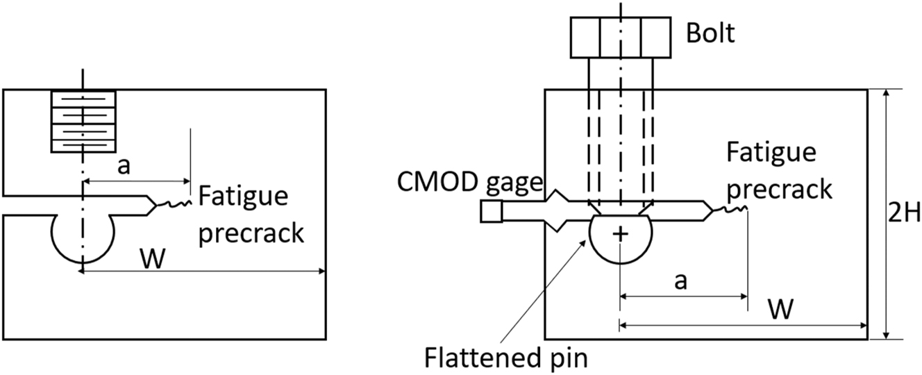
WOL (left) and modified WOL specimen (right). Adapted from Novak and Rolfe (1969) and ASTM E1681-03 (2020).
KIH measured under a sufficiently low loading rate and a properly measured KTH value converge in steels with yield strength (σ y) above 900 MPa (130 ksi) (Clark and Landes 1976; Gangloff 2003; Nibur et al. 2013). Pipelines have typically lower σ y, the grade with maximum specified minimum yield strength (SMYS) allowed for hydrogen service per ASME B31.12 code is the API 5L X80. As the actual σ y of such pipe must be between 555 and 705 MPa (80 and 102 ksi) (API 5L 2018), it is predicted that for pipeline steels, KTH >> KIH (Gangloff 2003; Nibur et al. 2013). Such result is extrapolated from behavior of higher strength steels but could never be proved. This is due to the challenges of measuring a crack arrest threshold in pipelines, where the material has a low yield strength, high toughness and small wall thickness. A review (Kappes and Perez 2023a) of the performance of materials extracted from pipelines in constant displacement tests reveals that a crack propagated only when a susceptible or high hardness region was located ahead of the crack tip. Such susceptible or high hardness region might be the result of an inappropriate welding procedure or an uncontrolled cooling of austenite during a thermal cycle.
Common constant displacement geometries presented in international standards are the modified wedge-opening-loaded (WOL) specimen (ASTM E1681 2020; ISO 7539-6 2018) (Figure 1) and the double-cantilever-beam (DCB) specimen (ISO 7539-6 2018; NACE TM0177 2016). There are also non-standardized tests, like the double torsion test (Shyam and Lara-Curzio 2006), which is attractive because KI is independent of crack length, except when the crack tip is near the specimen edges. The rationale behind crack arrest tests is that the fatigue pre-cracked specimens are initially loaded by a bolt, wedge or other loading device to a KI level below the fracture toughness value in air (KIC), Figure 2. After that it is introduced in an environment where hydrogen absorption or a stress corrosion cracking process enhances subcritical propagation of a crack. The crack might start growing after an incubation period and eventually arrest once the applied KI value decreases below the arrest threshold (KTH or KTSCC).
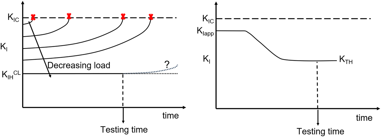
KI versus time dependence in tests at constant load (left) and constant displacement (right).
The purpose of this review is to revisit the details of the modified WOL test, focusing on the challenges arising on its use for characterizing KTH of pipeline steels exposed to gaseous hydrogen. This paper analyzes whether sizing requirements of ASTM E1681 can be fulfilled considering the required applied KI and the yield strength, wall thickness, and diameter of existing pipelines. Literature results of the modified WOL test are reviewed, to check if the restrictions imposed by the testing standards for a valid test were fulfilled. Alternatives to minimize oxide formation at the crack tip during loading in constant displacement tests are also analyzed. To avoid the inhibiting effect of those oxides on hydrogen absorption, dedicated devices are required. Finally, this work presents literature results on fracture mechanics tests of pipeline steels in gaseous hydrogen conducted under rising displacement, along with a discussion of the expected material behavior in a constant displacement test.
2 Rules for fracture toughness evaluation according to hydrogen pipeline design code
ASME B31.12 (2023) rules the design and construction of hydrogen pipelines operating at a pressure up to 21 MPa. In addition, it also has a detailed procedure for evaluating the possibility of transporting hydrogen in pipelines originally designed for a different service (like natural gas or liquid hydrocarbons).
ASME B31.12 (2023) has two different alternatives for considering HE effects. The prescriptive design method relies on higher safety coefficients, dependent on both steel strength level and operating pressure. The performance-based approach sets safety coefficients equal to those used for natural gas transport, after a successful fracture mechanics evaluation based on article KD-10 in ASME BPVC VIII-3 (2017). The aim of this evaluation is to determine if the pipeline has sufficient fracture toughness to resist propagation of a crack, given the size of existing flaws, operating pressure, and stress cycles. Additionally, the KTH or KIH CL value measured according to ASTM E1681 must be greater than 50 ksi.in1/2 (55 MPa m1/2). The analysis must be performed in base metal, welds and heat affected zones (HAZ) of welded joints, produced with the same welding procedure specification used for the pipeline fabrication.
3 Summary of the procedure for measuring KTH with modified WOL specimens
Novak and Rolfe proposed the modified WOL specimen in 1969 (Novak and Rolfe 1969). It is based on the WOL specimen proposed by Manjoine in 1965 (Manjoine 1965), intended to determine plane strain fracture toughness of steels for pressure vessels. The original WOL specimen had a hole for threading a pull bar and a hole to insert a pin and clevis assembly (Figure 1, left). Novak and Rolfe modified the WOL specimen using a bolt and a loading pin to stress it (Figure 1, right). In the original paper, the authors used bolt loaded specimens to determine KTSCC of two maraging steels with yield strength of 1,276 and 1,310 MPa (185 and 190 ksi), exposed to simulated seawater.
The modified WOL specimen is standardized in ASTM E1681-03 (2020) and ISO 7539-6 (2018). The scope of both standards is not limited to gaseous hydrogen, the environment can be any gaseous or liquid environment that promotes the propagation of a crack in metals. Details for gaseous hydrogen testing are presented in KD-10 article (ASME BPVC VIII-3 2017). ASTM E1681 provides two alternatives for EAC fracture mechanics tests: constant load or constant displacement. Constant load tests involve the use of beam specimens loaded by bending with a dead weight. Constant displacement tests use the modified WOL specimen, Figure 1. Several bolt-loaded specimens can be introduced in a single autoclave. They are also convenient for in-service measurements of the effects of real gas mixtures or solutions found in industrial environments.
At constant load, the driving force for crack growth increases with crack length. Depending on material performance and testing time, the outcome of the test could be a complete fracture, limited subcritical crack growth and no crack propagation, Figure 2. A limitation of constant load tests is that the incubation time for the onset of crack growth increases with a decrease in applied load (Anderson 2005). Even after following all ASTM E1681 recommendations, KIH CL has an intrinsic uncertainty, it is impossible to guarantee that the crack would not have propagated after a longer testing time, Figure 2. Constant displacement tests partly circumvent this issue by applying a large KI initially that favors the onset of crack growth, then KI decreases with crack advance, eventually arresting when KI = KTH, Figure 2. Nevertheless, tests with specimens instrumented with load cells reveal that propagation of a crack starts after a variable incubation time (Loginow and Phelps 1975; Nibur et al. 2013). A requirement of this testing method is that the testing time is sufficient for crack initiation and arrest, as schematized in Figure 2.
ASME B31.12 (2023) specifies that the orientation of the WOL specimen (Figure 1) must be in the TL direction (ASTM E399-09e2 2009). This means that the crack plane is normal to the circumferential direction and the expected direction of crack growth is in the longitudinal direction of the pipe. The TL direction is appropriate for characterizing longitudinal welds and HAZ. The characterization of circumferential welds and HAZ requires specimens cut in the LT direction (crack plane normal to longitudinal direction, crack expected to grow in the circumferential direction).
The specimen must be fatigue precracked under cyclic stressing in air. The bolt is tightened against the flattened pin, thus opening the crack while reading the indication given by the crack mouth opening displacement (CMOD) gage. The loaded specimen is introduced in the testing chamber (an autoclave, for pressurized gaseous hydrogen tests) until there is evidence of crack arrest or a pre-established period has elapsed. Detection of crack arrest requires that the pin is instrumented with a strain gage (Loginow and Phelps 1975). The strain gage measures the load at the pin, a decrease in load followed by a plateau indicates crack advance and arrest. The KD-10 article (ASME BPVC VIII-3 2017) establishes 1,000 h as a minimum testing time for pipeline steels exposed to hydrogen service. KD-10 article also indicates that the autoclave must be pressurized to the design pressure of the component and kept at room temperature. ASTM E1681-03 (2020) does not provide test duration time and recognizes that establishing test duration is one of the most difficult aspects of the test.
The stress intensity (KI) equation for the standard bolt-loaded specimen is.
where V m is the crack-mouth opening measured with the CMOD gage, E is Young’s modulus, W is the net width of the WOL specimen and f (a/W) is a function of the ratio between crack length (a) and W:
Valid for 0.3 < a/W < 1 and H/W = 0.486, where H is shown in Figure 1.
Equations (1) and (2) are used for setting the initial CMOD. Once the established test duration has elapsed, the specimen is removed from the autoclave, the specimen is broken to expose the crack and the initial and final crack sizes are measured. The KI value is calculated with Equations (1) and (2), using the final crack size. The ASTM E1681-03 (2020) standard states that KTH should be obtained with the lowest KIapp where there is evidence of crack advance.
4 Sizing of modified WOL specimens
ASTM E1681-03 (2020) modified WOL test is ruled by linear elastic fracture mechanics (LEFM) considerations. As in any other LEFM test, the minimum dimensions of the test specimen depend on steel yield strength (σ y ) and fracture toughness.
The specified minimum yield strength (SMYS) of steel pipelines is listed in API 5L (2018) and ISO 3183 (2019) specifications. Current SMYS of pipelines ranges from 175 MPa (25 ksi) to 830 MPa (120 ksi). The actual σ y of the pipeline in all cases must be equal or greater than the corresponding SMYS, and for pipes supplied under product specification level 2 (PSL 2), API 5L specification (API 5L 2018) also enforces an upper bound in σ y for each grade. The ASME B31.12 (2023) code places a limit of 80 ksi (grade X80) on SMYS for hydrogen pipelines designed under the performance-based design method. The code also lists ASTM grades, with a range in mechanical properties within that of API 5L grades.
Line pipe grades X46 and X52 were introduced in 1953, X60 in 1966, X65 in 1967 and X70 in 1973 (Kiefner and Trench 2001). Hence, for existing natural gas pipelines intended to be converted to hydrogen gas transport, the grade of the pipeline usually reflects the decade of construction (Kiefner and Trench 2001).
4.1 Selecting the initial KIapp
The initial applied stress intensity factor, KIapp, in a crack arrest test should be KTH < KIapp < KIC, Figure 2. Considering that the KTH is obtained at the end of the test, sound engineering judgement and previous knowledge of similar materials are required to estimate KIapp. Point KD-1045 in ASME BPVC VIII-3 (2017) states that KIapp should be 1.5 times greater than the estimated KTH but less than 198 MPa m1/2 (180 ksi.in1/2). The code provides a table with a range of recommended KIapp values for steels with yield strength between 621 MPa and 897 MPa (90 ksi and 130 ksi), Table 2.
KIapp values for ferritic steels as a function of yield strength, suggested in ASME BPVC VIII-3 (2017).
| σy | KIapp | ||
|---|---|---|---|
| MPa | ksi | MPa.m1/2 | ksi.in1/2 |
| 621 | 90 | 159–198 | 145–180 |
| 759 | 110 | 93–159 | 83–145 |
| 897 | 130 | 71–115 | 65–105 |
The rationale behind Table 2 is a well-accepted result of hydrogen embrittlement that dictates that, for a given steel microstructure, KTH increases with a decrease in yield strength (Bandyopadhyay et al. 1983; Echaniz et al. 1998; San Marchi and Somerday 2012; Yoshino and Minozaki 1986), hence, KIapp should increase as well. NACE TM0177 (2016) standard for measuring the stress intensity factor for crack arrest in hydrogen sulfide environments follows the same rationale, by imposing a larger CMOD with a decreasing yield strength. Extrapolating from Table 2, the KIapp for pipeline steels with an SMYS that is limited between 30 ksi (210 MPa) and 80 ksi (555 MPa) for hydrogen service (ASME B31.12 2023) should be well above 150 ksi.in1/2 (165 MPa m1/2). However, increasing KIapp is challenging in modified WOL tests because specimen dimensions increase with the square of KIapp, as will be shown below.
Point KD-1047 (ASME BPVC VIII-3 2017) allows setting KTH = KIapp/2 when there is no measurable crack propagation after the 1,000 h exposure time. It is interpreted that dividing the KIapp by two might yield a conservative KTH value, but the technical basis for this is not explained in the code. Taking into account that KTH = 55 MPa m1/2 is the minimum required value for base metal and welds according to option B of ASME B31.12, a pragmatic solution is setting KIapp = 110 MPa m1/2. If the crack does not propagate at this KIapp level, the pipeline would still be qualified for hydrogen service and the same safety coefficients as for natural gas service could be used per ASME B31.12 (2023) code. Furthermore, obtaining a valid KTH from a constant displacement test where the crack did not propagate is not considered in ASTM E1681-03 (2020).
A possible argument for setting KTH = KIapp/2 when the crack does not propagate could arise from an analysis of results by Nibur et al. (2013) on pressure vessels steels, Table 3. The table shows KTH measured according to ASTM E1681 and the maximum value of KIapp that resulted in no crack propagation. In all cases, KTH > 50 % max. KIapp for no crack propagation. However, extrapolating such result to pipeline steels exposed to gaseous hydrogen is unwarranted, especially considering that for such steels there are not reliable measurements of crack arrest values measured according to ASTM E1681. Notice in Table 3 that as the yield strength of the steel decreases, the maximum KIapp for no crack propagation increases, which also provides a basis to argue that KIapp for pipeline steels should be well above 144 MPa m1/2.
KTH and maximum KIapp for no crack propagation for four low alloy steels used for pressure vessel fabrication, after Nibur et al. (2013).
| Alloy | σ y, MPa (ksi) | KTH MPa.m1/2 | Maximum KIapp for no crack propagation MPa.m1/2 |
|---|---|---|---|
| DOT-3AAX | 641 MPa (93) | 87 | 144 |
| SA 372 grade J | 717 MPa (104) | 93 | 137 |
| SA 372 grade J | 736 MPa (107) | 97 | 105 |
| DOT 3T | 900 MPa (131) | 35 | 60 |
The following sections will show that even if KIapp is set to 110 MPa m1/2, for common geometries and mechanical properties of pipelines it is impossible to extract a standard modified WOL specimen that fulfills all ASTM E1681 restrictions.
4.2 Specimen thickness and side grooves
For air tests, the fracture toughness decreases with an increase in the thickness of the specimen (B) under study (Anderson 2005), eventually reaching a plateau. The thickness independent fracture toughness has traditionally been named plane strain fracture toughness (KIC). The following requirement is indicative of plane strain conditions along the crack front (Joyce and Tregoning 2000), so that a conservative KIC value is obtained:
Similar considerations are held for the environment affected fracture toughness test (ASTM E1681), where KIC should be replaced by KTH.
The thickness effect on measured fracture toughness is a consequence of the relative contributions of the shear fracture near the specimen sides and the flat fracture on the specimen center, where plane strain conditions prevail (Anderson 2005). The use of side-grooved specimens creates plane strain conditions along the entire crack front and could eliminate the shear fracture contribution (Nibur et al. 2013), even when the requirement of Equation (3) cannot be satisfied.
Besides eliminating shear lips, side grooves could help to guide the crack along a single plane and to produce a straight fronted crack (ASTM E1681-03 2020). The ASTM E1681 standard allows up to a 20 % total reduction in thickness by side grooves. Although Equation (1) is independent of thickness, the presence of side grooves affects the estimated value of applied and arrest stress intensity factors. Equation (1) was obtained by combining expressions of KI (as a function of applied load and geometry) and of compliance, both of which have different dependences on total and reduced thickness. This generated a correction factor that for 16 % side grooves increases the K value about 4 % relative to the value determined if the side grooves were ignored (Nibur et al. 2010).
In the original paper by Novak and Rolfe (1969) 1 inch (25.4 mm) thickness specimens of maraging steels (σ y = 1,276 (185) and 1,310 (190) MPa (ksi)) were loaded to around 90 ksi.in1/2 and, exposed to synthetic seawater. After propagation of the crack and arrest, KISCC was 43.6 ksi.in1/2 and 52 ksi.in1/2. Hence, the requirement of plane strain condition in Equation (3) was fulfilled from the beginning to the end of the test. Semicircular side grooves were optional in the modified WOL geometry proposed by Novak and Rolfe. They had a depth equal to 5 % of the specimen thickness. In all cases, after the test ended, examination of fracture surfaces revealed that a flat fracture surface propagated in the environment. Loginow and Phelps (1975) also used 5 % side grooves for studying KTH of various pressure vessel steels exposed to pure hydrogen. The thickness was also 1 inch, and plane strain conditions prevailed at crack arrest. The crack front was planar and essentially straight. For different pressure vessel steels studied by Nibur et al. (2013), that did not fulfill Equation (3) requirement, 16 % side grooves eliminated shear lips along the entire crack length, suggesting that plane strain conditions dominated.
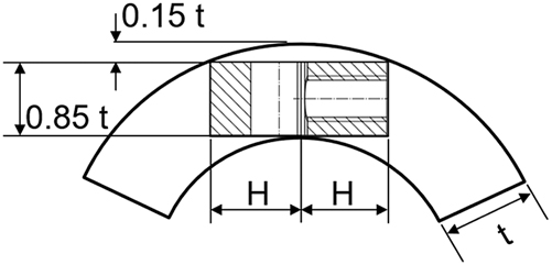
For pipeline steels, using 50 ksi.in1/2 for the minimum KTH admitted by the ASME B31.12 code, and considering the range of possible SMYS values, Equation (3) requires a minimum B of about 176 mm (7 inches) for an API 5L grade A pipeline and 25 mm (1 inch) for an X80 pipeline, well above the wall thickness commonly found in pipelines. The KD-10 article (ASME BPVC VIII.3 2017) allows to set the thickness of the modified WOL specimen equal to 85 % of the wall thickness of the component under study. When the requirement of Equation (3) is not met, ASTM E1681 indicates that KTH is thickness dependent (in the standard KIEAC and KEAC are used to refer to plane strain and thickness dependent parameters, respectively, Table 1). The usefulness of a thickness dependent parameter for integrity evaluations (like allowable pressure or critical crack size, Kappes and Perez 2023b) is questionable, even when the thickness of the modified WOL specimen is similar to that of the component under evaluation (Anderson 2005). The reason is that depending on component and crack geometry and orientation, the size of the high triaxiality zone ahead of the crack might not depend on the specimen thickness, Figure 3. A KTH value obtained with the specimen on the left, even when B = 0.85 t, could not be adequate to estimate the stability of the crack in the structural component showed on the right. The relative contribution of shear fracture in the test specimen is larger than in the structural component, even when B = 85 % t.
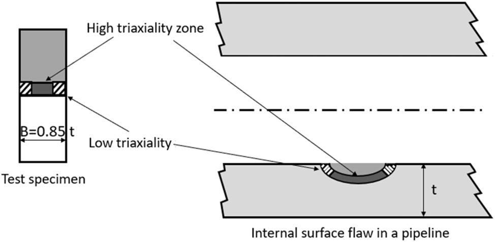
Comparison of zones with high and low triaxiality ahead of a crack in a fracture mechanics test specimen with thickness B (left), and ahead of a surface crack in a component of thickness t (right). Notice that in the right, the stress state and hence fracture morphology might not be directly related to specimen thickness. Adapted from Anderson (2005).
4.3 Specimen width (W)
According to ASTM E1681, a valid KTH requires that the remaining ligament (W−a) fulfills Equation (4).
This ensures that the plastic zone is sufficiently small so that the fracture is under LEFM regime. Notice that in ASTM E1681, the above condition is placed using KTH, not KIapp. However, taking into account that KD-10 article (ASME BPVC VIII.3 2017) considers that a valid test can be obtained even when the fracture did not propagate, the relation as shown in Equation (4) provides the most conservative condition. A valid test requires a higher W as the a/W ratio increases and the yield strength decreases. Using 110 MPa m1/2 for KIapp, Equation (4) requires a minimum W−a of about 359 mm (14 inches) for an API 5L grade A pipeline and 50 mm (2 inches) for an X80 pipeline. Figure 4 shows minimum W values for different API 5L pipeline grades and different a/W ratios. For a better visualization of the data, the figure is restricted to grades with SMYS equal to or greater than 42 ksi, which are the most common in existing pipelines.
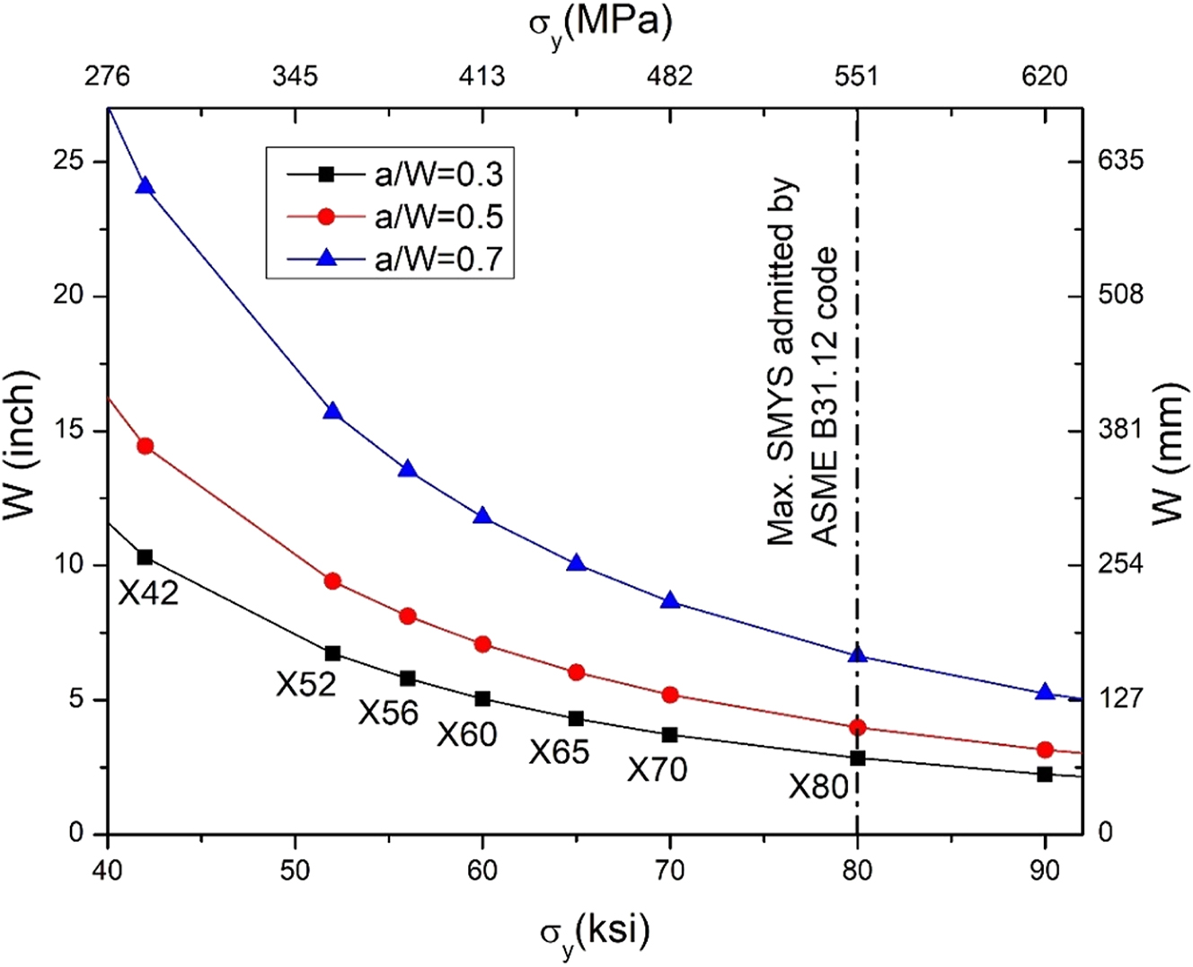
Minimum W required by ASTM E1681-03 (2020) for different API 5L pipeline grades and a/W ratios. It is considered that for each grade σ y = SMYS.
4.4 Specimen height (2H)
In the standard configuration (ASTM E1681-03 2020, ISO 7539-6 2018), the modified WOL specimen has an H/W ratio of 0.486. For specimens cut in the TL direction, the curvature of the pipeline might preclude fulfilling this condition on H, Figure 5. Considering that the specimen width must be at least 85 % of the wall thickness (t), the following relationship holds between the maximum possible value of H and the pipeline external diameter (Dext):
Extraction of a modified WOL specimen in the TL direction from a pipeline segment, showing standard height and B equal to 85 % of t.
Solving for the required external diameter Dext,req when H/W = 0.486:
Figure 6 shows Dext,req for obtaining WOL specimens of the standard geometry. Dext,req rises with an increase in a/W and a decrease in t. The increase in the required Dext with a decrease in pipeline yield strength is explained considering Figure 4.
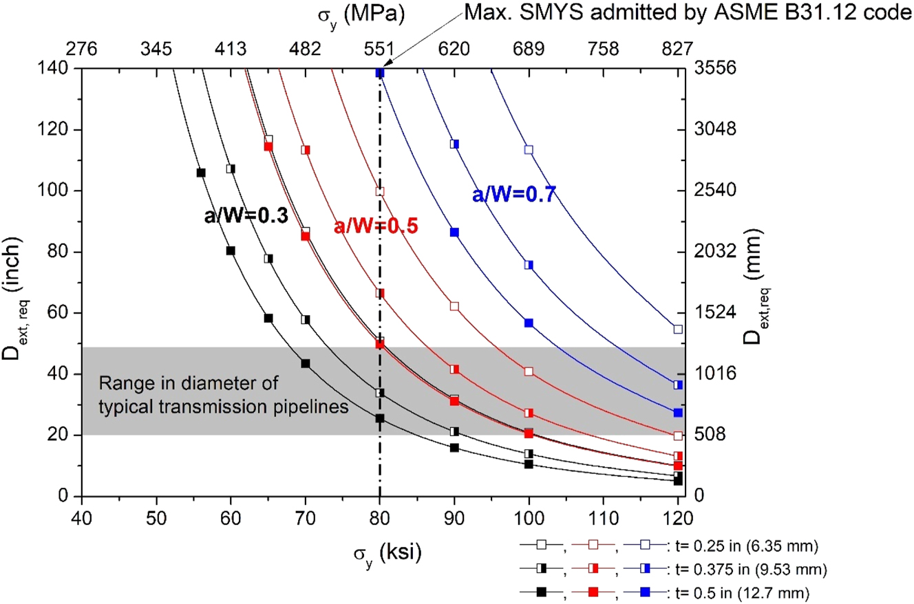
Dependence of minimum external diameter of pipeline required to obtain standard ASTM E1681 modified WOL specimens (H/W = 0.486), for different values of pipeline wall thickness (t), a/W ratios and pipeline yield strengths.
For the range of diameters typically (Folga 2007) found in transmission pipelines (shaded in gray in Figure 5), specimens with a/W = 0.5 can only be obtained when the actual σ y is above 80 ksi. A modified WOL specimen made from a pipeline with σ y = 65 ksi or below and with a wall thickness up to 0.5 in (12.7 mm) requires a diameter higher than the maximum pipe diameter typically found in transmission pipelines. For existing natural gas transmission pipelines with actual σ y between 42 and 80 ksi and wall thickness up to 0.5 in (12.7 mm), it is impossible to obtain specimens with the conventional H/W ratio and a/W = 0.5 or a/W = 0.7. Whenever specimens with H/W = 0.486 cannot be obtained from the parent product, the investigator must procure the corresponding coefficients in Equations (1) and (2) by numerical modelling, adding costs and time to the project.
The limitation depicted in Figure 5 applies also for obtaining specimens in the LT direction, required for characterizing circumferential welds and HAZ. In the LT direction, the modified WOL specimen could have an unlimited value of H, but W will be limited by pipeline curvature. Considering that 2H < W (Figure 1), obtaining specimens in the LT direction is even more stringent than in the TL direction. The use of hot or cold flattening of the pipeline is not acceptable because the steel microstructure and the fracture mechanical properties would be affected.
5 Load and normal stress in the bolt
The required crack-mouth opening (Vm) to reach the minimum KIapp applied can be obtained from Equation (1).
In the LEFM regime, an increase in Vm implies a proportional increase in load in the bolt (P). Such dependence was presented by Lisagor (1984),
where B is the thickness of the WOL specimen with H/W = 0.486 and g (a/W) is given by:
Replacing Equation (7) in Equation (8):
A valid test requires W−a given by Equation (4), which can be rewritten as:
Replacing the minimum possible value of W into Equation (10) yields:
The normal stress (σ) in the bolt will be:
where d is the bolt diameter. The bolt diameter is limited by B, for example ASTM E1681-03 (2020) sets:
Replacing Equations (12) and (14) into (13):
Using Equation (15) with KIapp of 110 MPa m1/2 (100 ksi.in1/2), the stress in the bolt for WOL specimens with the standard configuration (H/W = 0.486) is plotted as a function of pipeline yield strength, wall thickness (t) and a/W ratio (Figure 7). B was set equal to 0.85 t, according to KD-10 article (ASME BPVC VIII.3 2017) requirement.
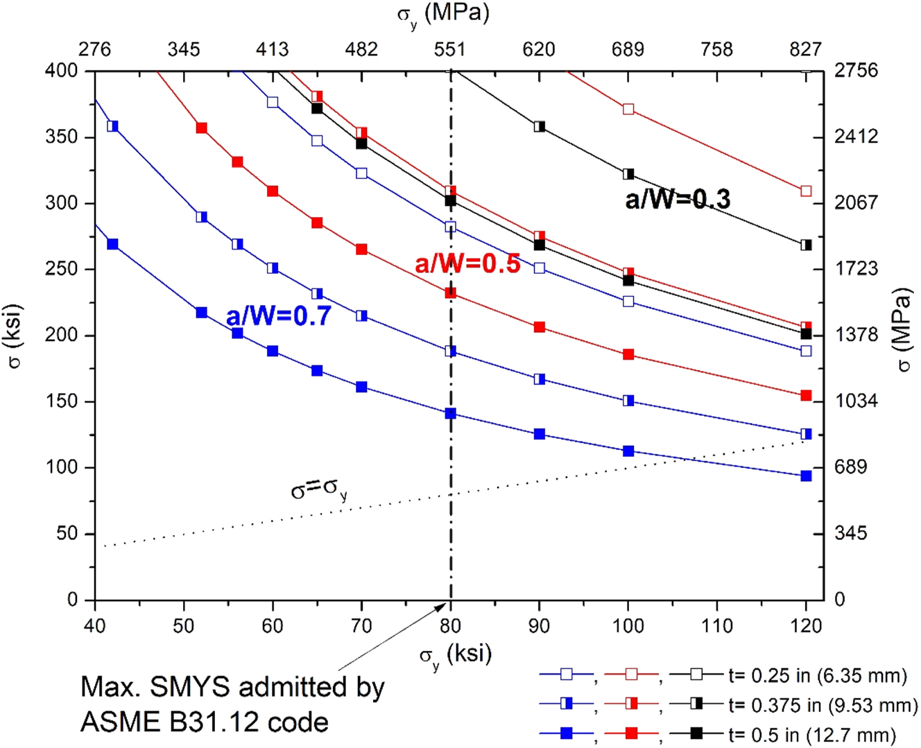
Stress in the bolt of modified WOL specimens obtained from pipelines with different yield stress, loaded to 110 MPa m1/2. B equal to 85 % of the pipeline wall thickness (t), W according to Equation (4) and a/W values as indicated.
The very high-predicted stress in the bolt shown in Figure 7 is a consequence of adapting B equal to 85 % of the pipeline wall thickness, rather than setting it equal to 0.5 W, as suggested by ASTM E1681. However, it is impossible to adopt this B value in pipelines encountered in practice given the increase in required W with decreasing yield strength, Figure 4. From Figure 7 it is concluded that an increasing a/W ratio decreases the stress in the bolt. However, for the span of diameter of pipelines used in practice and the range of SMYS admitted by ASME B31.12 code, specimens with a/W = 0.5 or a/W = 0.7 cannot be obtained, Figure 6. A well lubricated bolt would be under compressive stresses, but reaching such high stresses requires an elevated torque during the loading operation, which raises the risk of shear failure of the bolt.
It is noticed that for the standard configuration of ASTM E1681-03 (2020), setting B = W/2 in Equation (15), the stress in the bolt would be:
As shown in Figure 8, the stress in the bolt is below the yield strength of the pipeline for a/W = 0.5 and a/W = 0.7. For a/W = 0.3, it is slightly above the yield strength, which is not a problem if the bolt is to be machined from the same metal under study because steels used for pipelines and pressure vessels have some strain hardening capacity. Otherwise, the bolt can be fabricated with a higher strength steel. The stress in Figure 8 is independent of KI. This is because as KI increases, W by Equation (4), B and bolt diameter d Equation (14) also increase.
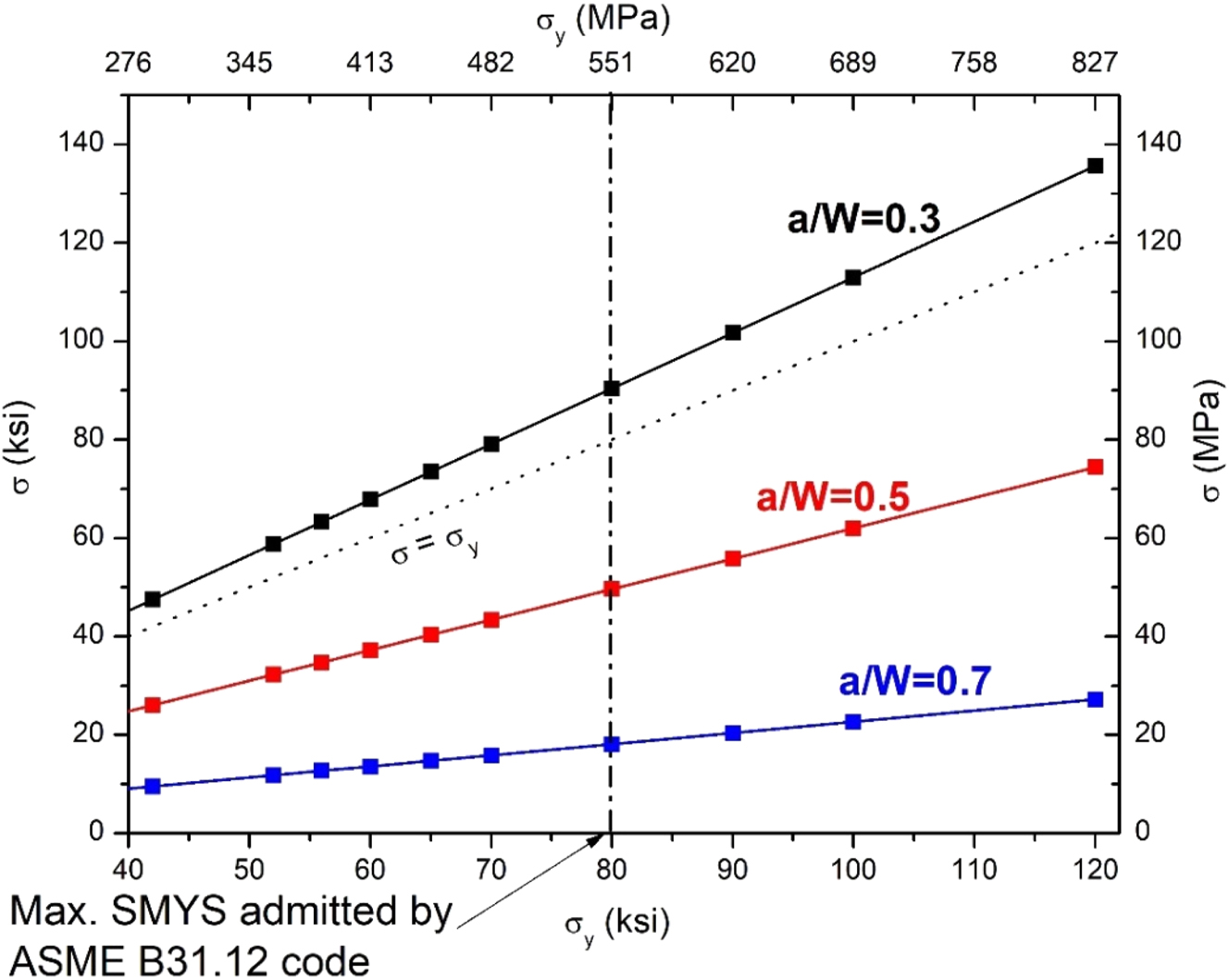
Stress in the bolt of modified WOL specimens obtained from pipelines with different yield stress, with W according to Equation (4), B equal to 0.5 W, and a/W values as indicated.
6 Discussion
6.1 Review of results obtained on pipeline steels at constant displacement
Table 4 summarizes literature results of constant displacement tests in gaseous hydrogen obtained on steels with mechanical strength within that of pipeline steels. Tazedakis et al. (2021) studied API 5L grades X60, X65 and X70, with actual σ y between 492 and 539 MPa (71–78 ksi) in 8 MPa H2 and with an KIapp between 110 MPa m1/2 and 144.6 MPa m1/2. The authors reported no crack propagation at the end of the 1,000 h testing period. The specimens were sized following the recommended configuration in ASTM E1681, W = 2B. However, all the specimens had a W-a value lower than the ASTM E1681 requirement in Equation (4), so the test is invalid according to KD-10 article in ASME BPVC VIII-3 (2017).
Results of constant displacement tests reported in literature for carbon and low-alloy steels with mechanical strength within the range of pipeline steels.
| Steel grade | pH2 MPa | σ y MPa (ksi) | UTS MPa (ksi) | Comments | Reference | |
|---|---|---|---|---|---|---|
| API 5L X70 | 4.14 | 613 (89) | 702 (102) | Base metal, compact specimen; no crack propagation | Cialone and Holbrook (1988) | |
| API 5L X42 | 6.9 | 311 (45) | 490 (71) | HAZ of electric resistance welded pipe, compact specimen; no crack propagation | ||
| API 5L X42 | 4.14 | N/A | N/A | Austenitized and quenched to simulate hard spots (38 HRC), compact specimen; crack propagated. | ||
| API 5L X80 | 31 | 676 (98) | 794 (115) | No crack propagation in base metal; uneven crack growth in weld specimens along HAZ with 42 HRC | Xu (2012) | |
| API 5L X60 | 8.0 | 492 (71) | 612 (89) | Tests in base metal and bond line of high frequency welded pipeline | Modified WOL specimen with W-a < minimum required in Equation (4); no crack propagation after 1,000 h of testing at KIapp ≥ 110 MPa m1/2 | Tazedakis et al. (2021) |
| 498 (72) | 627 (91) | |||||
| API 5L X65 | 524 (76) | 605 (88) | ||||
| API 5L X70 | 539 (78) | 655 (95) | ||||
| 496 (72) | 614 (89) | Tests in base metal, HAZ and weld metal of submerged arc welded pipeline | ||||
| A516 | 69 | 290 (42) | 572 (83) | KIapp = 82 MPa m1/2 | Modified WOL specimen with 25.4 mm of thickness; pressure vessels steels; no crack propagation | Loginow and Phelps (1975) |
| A106 | 97 | 345 (50) | 558 (81) | KIapp = 55 MPa m1/2 | ||
| HY-80 | 69 | 586 (85) | 689 (100) | KIapp = 116 MPa m1/2 | ||
| X65 | 40 | 501 (73) | 594 (86) | No crack propagation after 1,000 h of testing, at KIapp between 117 MPa m1/2 and 187 MPa m1/2; W−a < minimum required in Equation (4), validated by finite element modelling | Cravero et al. (2023) | |
Cravero et al. (2023) studied an API 5L X65 (with actual σ y = 501 MPa = 72.7 ksi) in 40 MPa H2 at KIapp between 117 MPa m1/2 and 187 MPa m1/2. Similarly to Tazedakis et al. work, W was set equal to 2B. The pipe had a wall thickness of 19 mm, which is in the upper range of wall thickness typically encountered in existing pipelines. The authors acknowledge that (W−a) was smaller than required per ASTM E1681. The smaller specimen size was validated numerically, showing that the difference between KIapp calculated from an elastic-plastic finite element model and the prediction from linear elastic solution (Equation (1) and (2)) was less than 5 % for KIapp up to 112 MPa m1/2. Incidentally, an increment in the initial crack size increased the maximum KIapp admitted according to the finite element modelling validation. This is also beneficial because an increase in a/W decreases the load in the bolt. Finite element modelling was also applied to reduce the conservatism of Equation (4) by Nibur et al. (2010). In one of the tests on a pressure vessel steel with σ y = 717 MPa, the crack extended up to a/W = 0.81, so that the remaining ligament was below the minimum required by Equation (4). However, the differences between KTH calculated with Equation (1) and (2), a finite element analysis assuming small scale yielding, and an elastic plastic analysis were all within a 10 % error. Furthermore, comparing results from a small scale yielding versus an elastic plastic model, there was less than 2 % difference in the magnitude of opening stresses on the plane of symmetry ahead of the crack.
Loginow and Phelps (1975) studied several pressure vessel steels in H2 at a pressure ranging from 21 to 97 MPa. The tested steels with lower strength had a σ y between 290 MPa and 586 MPa (42 ksi to 85 ksi), which is in the range of actual σ y of pipeline steels admitted by ASME B31.12 code. In none of those steels, the authors observed crack propagation. The specimens had a thickness of 25.4 mm and were loaded to KIapp ranging from 55 to 116 MPa m1/2. While the applied KIapp was in some cases low considering current requirements of testing standards, it is acknowledged that this paper preceded the first editions of ASTM E1681-03 (2020) and ASME BPVC VIII-3 (2017). Loginow and Phelps also tested pressure vessel steels with σ y between 586 MPa and 1,055 MPa (85 ksi–153 ksi), which exhibited crack propagation and arrest in pressurized hydrogen. However, those results are not included in the table because their strength is well above that of pipeline steels.
Subcritical crack growth was not detected in constant displacement tests performed in compact specimens (Cialone and Holbrook 1988) in gaseous hydrogen and mixtures, in base metal and heat affected zones of X70 and X42 pipeline steels, respectively.
Two papers (Cialone and Holbrook 1988; Xu 2012) reported crack propagation in pipeline steels exposed to gaseous hydrogen in constant displacement tests. In both studies, the metal had an unusually high hardness (>38 HRC) and susceptible microstructure, resultant from a quenching process or fast cooling in the HAZ of an inappropriate welding procedure.
Considering the stringent restrictions detailed in the previous sections and the high load in the bolt, in all studies on base metal of linepipe steels found by the authors of the present paper, at least one of the requirements imposed by the testing standards was not fulfilled. The lack of valid tests reported in literature is at odds with the fact that there is a wordwide interest in qualifying existing transmission pipelines for hydrogen gas transport. While finite element modelling could reduce some of the conservatism in sizing restrictions, it must be done case by case adding time and costs to experimental programs. Additionally, crack propagated only in regions of unusually high hardness or susceptible microstructure. In this regard, ASME B31.12 (2023) places a restriction of 235 HV (Vickers hardness) on base metal, weld and HAZ. This hardness is less than 20 HRC (Rockwell hardness in scale C). Hence, the cases where crack propagated in Table 4 had an unacceptable hardness according to ASME B31.12.
6.2 Review of results obtained on pipeline steels following ASTM E1820 methodology
Although ASTM E1820-20b (2020) is not currently considered by ASME B31.12 for characterization of hydrogen affected fracture toughness, literature results obtained with this testing procedure are useful for getting some conclusions about material performance in constant displacement tests. For instance, it is accepted (Al-Rumaih and Gangloff 2005; Nibur et al. 2013) that for steels with σ y < 900 MPa, the KIH obtained under slowly raising CMOD provides a lower bound estimate of the value to be obtained in constant CMOD tests (ASTM E1681-03 2020). Even though ASTM E1820 is a standard originally developed for air tests of fracture toughness, its procedure for obtaining the onset of crack extension from J or CTOD measurements is extrapolated to tests performed in a pressurized autoclave with H2. Most authors calculate KIH from JIC obtained using the 0.2 mm offset curve traced parallel to the blunting line curve according to ASTM E1820. Notice that KIH describes resistance to crack initiation plus a small amount of crack extension (Nibur et al. 2010). KIH is obtained from JIH and CTODH according to (ASME BPVC VIII-3 2017), using Equations (17) and (18).
where the subscript H indicates that the measurements are conducted in pressurized hydrogen and ν is Poisson ratio. The onset of crack extension can be estimated with the direct current potential drop (DCPD) technique. DCPD monitors crack length by applying a constant current through the specimen and measuring the potential drop at the crack mouth, an increase in the potential drop can be related to an increase in crack length (ASTM E1820-20b 2020). However, the actual value for the onset of crack extension is very sensitive to the interpretation of the DCPD data, hence, the 0.2 mm offset construction of ASTM E1820 for tests in air is widely adopted.
Table 5 is a non-exhaustive list summarizing measurements of KIH obtained from J integral or CTOD tests normalized in ASTM E1820, performed in pressurized pure hydrogen in base metal of pipeline steels. For most reported tests, KIH is greater than 100 MPa m1/2. Similar results were recently reported by Steiner et al. (2023). KIH of steels from many pipeline grades used in German natural gas transmission network were analyzed in 10 MPa H2 and in most cases KIH was also >100 MPa m1/2 for the base metal.
Literature results on KIH in base metal of API 5L pipeline steels in pressurized hydrogen.
| API 5L grade | pH2 MPa | σ y, MPa (ksi) | UTS, MPa (ksi) | KIH MPa.m1/2 | Displacement rate m/s | K rate MPa.m1/2/s | Testing technique | Reference |
|---|---|---|---|---|---|---|---|---|
| X42 | 6.9 | 311 (45) | 490 (71) | 107 | 2.5 × 10⁻⁶ and 2.5 × 10⁻⁷a | Not reported | J integral | Cialone and Holbrook (1988) |
| X52 | 21 | 429 (62) | 493 (72) | 105 | 8.3 × 10⁻⁸ and 8.3 × 10⁻⁷a | 0.05 and 0.005a | J integral | Ronevich and San Marchi (2021) |
| X60 | 20.7 | 435 (63) | 486 (71) | 84 | 8.3 × 10⁻⁸ and 8.3 × 10⁻⁷a | 0.05 and 0.005a | J integral | Stalheim et al. (2010) |
| X60 | 1.55 | 407 (59) | 565 (82) | 111 | Not reported | 3.3 × 10⁻⁵ MPa m1/2/s | J integral | Bezensek et al. (2023) |
| 115 | 1.6 × 10⁻⁴ MPa m1/2/s | |||||||
| 121 | 1.7 × 10⁻³ MPa m1/2/s | |||||||
| 132 | 1.7 × 10⁻² MPa m1/2/s | |||||||
| X65 | 25 | 622 (90) | 640 (93) | 140 | 2.0 × 10⁻⁶ | Not reported | J integral | Nishihara and Okano (2023) |
| 487 (71) | 575 (83) | 150 | ||||||
| 570 (83) | 643 (93) | 164 | ||||||
| X70 | 10 | 600 (87) | 632 (92) | 105 | 1.7 × 10⁻⁵ | Not reported | CTOD | Nguyen et al. (2021) |
| X70 | 8.5 | 594 (86) | 622 (90) | 131 | 8.3 × 10⁻⁶ | Not reported | CTOD | Briottet and Ez-Zaki (2018) |
| X70 | 6.9 | 613 (89) | 702 (102) | 94 | 2.5 × 10⁻⁶ and 2.5 × 10⁻⁷a | Not reported | J integral | Cialone and Holbrook (1988) |
| X70 | 21 | 565 (82) | 600 (87) | 102 | 8.3 × 10⁻⁸ and 8.3 × 10⁻⁷a | 0.05 and 0.005a | J integral | San Marchi et al. (2010) |
| X80 | 20.7 | 541 (79) | 596 (86) | 107 | 8.3 × 10⁻⁸ and 8.3 × 10⁻⁷a | 0.05 and 0.005a | J integral | Stalheim et al. (2010) |
-
aNo significant differences in measured KIH.
The sizing requirements in ASTM E1820 are.
where ν = 0.3 was adopted for ferritic steels. Considering the respective SMYS for pipeline steels, σ y/E ranges from 1.4 × 10⁻³ for an API 5L X42 up to 2.8 × 10⁻³ for an API 5L X80. Hence, the sizing requirements of ASTM E1820 are much more lenient than those of ASTM E1681 (Equations (3) and (4)). For example, for KIH = 164 MPa m1/2 (largest value in Table 5) and σ y = 290 MPa (SMYS of an API 5L X42), the thickness B and initial uncracked ligament should be greater than 4.2 mm. A specimen with such dimensions can be easily extracted from most high-pressure transmission pipelines. However, validity of the test according to ASTM E1820 standard also requires straightness of the crack front. In this regard, crack tunneling and delamination have been reported after rising displacement tests of pipeline steels in gaseous hydrogen (San Marchi et al. 2010, 2011), which can prevent meeting the requirement for straightness of crack propagation.
For rising displacement tests in gaseous hydrogen, a key experimental parameter that has a direct effect on the measured KIH value and J curve is the load displacement rate. A too rapid rate can grow the crack at a faster rate that hydrogen can diffuse ahead of it and towards the region of high triaxial stresses near the crack tip. Tests performed by Clark and Landes (1976) on a type 4340 Ni–Cr–Mo steel with σ y = 1,240 MPa in 0.55 MPa H2 showed that KIH decreased from 77 to 30 MPa m1/2 when the loading rate decreased from 0.8 MPa m1/2/s to 2 × 10⁻³ MPa m1/2/s. At the low loading rate, the KIH value measured on this high strength steel was equivalent to the KTH measured at constant displacement, Figure 9. Similar results were reported by the author at a σ y = 1,102 MPa. Bezensek et al. (2023) tested the base metal of API X60 steel in 1.55 MPa H2, at different loading rates ranging from 1.7 × 10⁻² MPa m1/2/s down to 3.3 × 10⁻⁵ MPa m1/2/s. In this range of K rate, KIH decreased from 132 to 111 MPa m1/2, Table 5. In addition to the effect on KIH, the displacement rate decreased the slope of the J curve (Bezensek et al. 2023). Hence, besides the effect on KIH, an increment in the K rate increased the difference between JIH at the 0.2 mm offset line and the corresponding value measured at the onset of crack growth. For the smallest K rate of 3.3 × 10⁻⁵ MPa m1/2/s, both parameters were similar. However, guidelines on proper loading rates for pipelines are still under development (EPRG 2024), and it is currently recommended to explore the effect of loading rate at the beginning of a testing program. For instance, similar KIH values were measured at 0.05 and 0.005 MPa m1/2/s in tests by San Marchi et al. (2010). Cialone and Holbrook (1988) did not observe differences in KIH of API 5L X42 and X70 in 6.9 MPa H2 measured at a displacement rate of 2.5 × 10⁻⁶ and 2.5 × 10⁻⁷ m/s, Table 5. The K rate during elastic loading is controlled by load displacement rate, specimen geometry and dimensions and machine compliance.
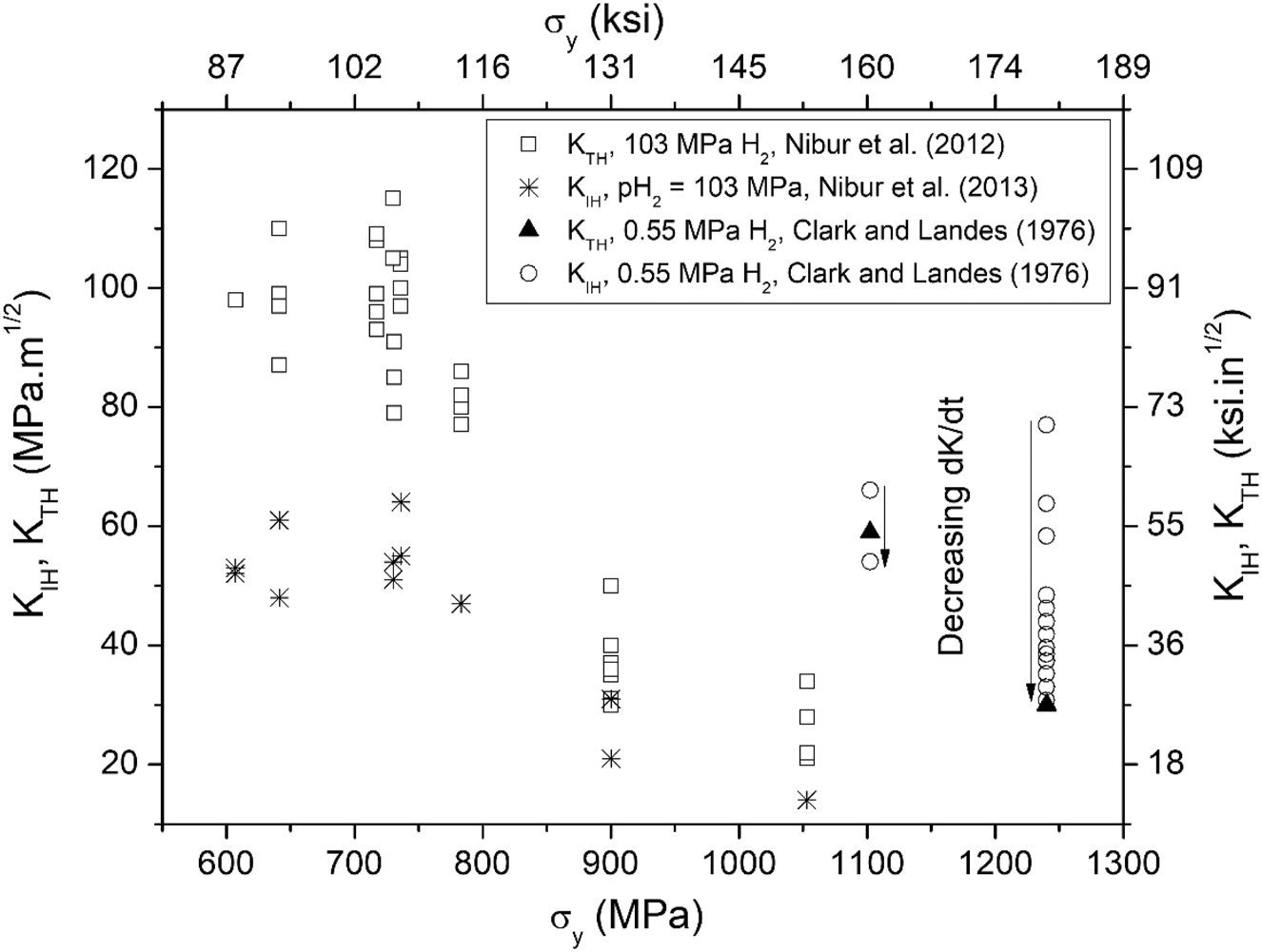
Comparison of KTH and KIH for pressure vessel steels in pressurized gaseous hydrogen, after Nibur et al. (2013) and Clark and Landes (1976).
6.3 The relationship between KIH measured with ASTM E1820 and KTH measured with ASTM E1681
KIH measured under rising CMOD and KTH measured under constant CMOD represent critical stress intensity values for different processes (Nibur et al. 2013). In a rising CMOD test (ASTM E1820-20b 2020), hydrogen absorption and plastic straining at the crack tip are simultaneous and KIH is the KI value required for measurable crack advance. In a constant CMOD test, first the specimen is mechanically loaded in an inert environment, which generates a plastic deformation gradient near the crack tip. Afterwards, the loaded specimen is exposed to the environment where atomic hydrogen is absorbed at the crack tip and is transported to the fracture process zone. The crack propagates and is arrested at KTH. Plastic strain in metals implies dislocation movement, and dissolved hydrogen enhances this movement (Robertson et al. 2015). As fracture is assisted by localized plastic strain, the different plastic deformation histories near the crack tip in both tests partly explain differences in critical stress intensity parameters. Additionally, for elastoplastic materials that require a critical amount of crack tip strain for cracking, like pipelines, different values of KIH and KTH are predicted based on differences in the strain field ahead of a stationary versus propagating crack (Nibur et al. 2013). Those are possible reasons for the fact that, for steels with σ y < 900 MPa, KIH < KTH (Al-Rumaih and Gangloff 2005; Gangloff 2003; Nibur et al. 2013), Figure 9.
As reported in item 4.1, the minimum KIapp for qualifying a steel for hydrogen service is 110 MPa m1/2. Comparison of KIapp with KIH in Table 5, indicates that:
Notice that pipeline steels for hydrogen service have an actual σ y that ranges between 210 MPa and 705 MPa per ASME B31.12 (2023) code and API 5L (2018). Extrapolating the result in Figure 9, obtained on pressure vessels steels, to pipeline steels:
Hence, even if a standard modified WOL specimen could be extracted from the base metal of a pipeline steel, the expected outcome of the test would be “no crack propagation” at KIapp = 110 MPa m1/2, unless the region ahead the crack tip has a highly susceptible microstructure or an unusually high hardness, Table 4. A susceptible microstructure or a high hardness region can be more effectively and economically evaluated by metallographic observation or microhardness testing. In this regard, a major limitation of fracture mechanics tests applied to the characterization of microstructural and chemical inhomogeneities in a material is the difficult alignment of the crack plane with the most susceptible zone in the material.
Figure 10 presents another challenge of measuring KTH with a constant displacement test in a material that has a rising JR curve (bold curve in Figure 10), like pipeline steels in pressurized hydrogen environment (Bezensek et al. 2023; Cialone and Holbrook 1988; San Marchi et al. 2010). This challenge arises purely from mechanical effects (Anderson 2005). CMOD curves represent the crack driving force J at constant displacement, with CMODi < CMODi+1. The crack driving force decreases at constant displacement as the crack advances. The intersection point of crack driving force with JR curve defines the crack arrest point. The higher the initial crack driving force, the higher the ordinate of the intersection. Considering that
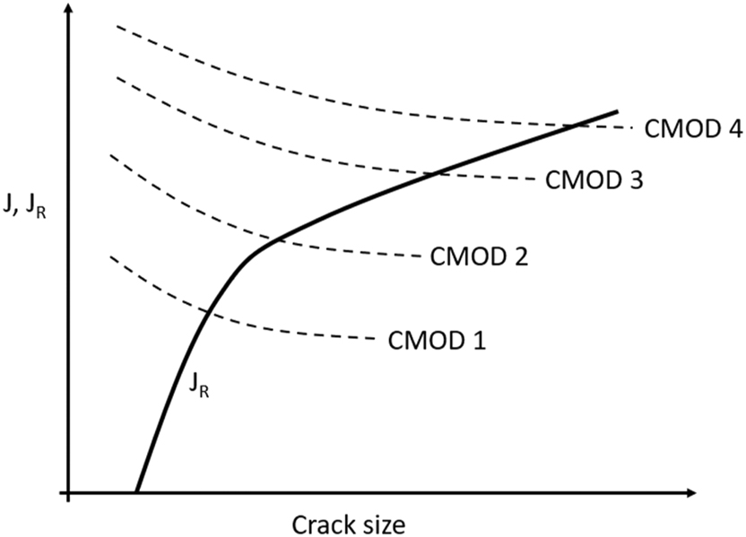
Driving force (J) for crack propagation under different values of constant displacement (Δi < Δi + 1) and material resistance to crack advance (JR), adapted from Anderson (2005).
6.4 On the risk of subcritical cracking at KI below KIH
For pipelines, although KIH values measured under rising displacement conditions provide conservative results in comparison to modified WOL specimens, such values should not be interpreted as immunity “thresholds” for hydrogen stress cracking. While the concept of “thresholds” (ASTM E1681-03 2020) has extensive use in engineering practice, fundamental studies conducted in the last decades have questioned their validity. Various authors performed in situ crack growth rate tests, according to experimental procedures proposed by Andresen (Andresen 1988, 2019) and using high resolution systems capable of resolving crack propagation rates below 10−9 mm/s. Those tests showed that there is a sustained, measurable crack propagation rate below thresholds traditionally accepted for cracking of structural materials in high temperature water. Experimental procedures involve the transitioning of cyclic loading of a fatigue crack to sustained loading conditions, by gradual increasing the load ratio (R = Kmin/Kmax, where Kmin and Kmax represent minimum and maximum KI applied during a stressing cycle) and the time spent at Kmax. This testing technique proposed by Andresen (Andresen 1988, 2019) has recently expanded beyond the nuclear materials field and was used to study EAC of pipeline steels and corrosion resistant alloys used in oil and gas service (Sridhar et al. 2017; Thodla et al. 2020). Recently Bezensek (Bezensek et al. 2023) applied this methodology to a pipeline steel in gaseous hydrogen.
Bezensek et al. (2023) evaluated an API 5L X60 steel in 1.5 MPa H2. It was first fatigue loaded, at ΔK of 35 MPa m1/2 and ΔK values were decreased until 2.2 MPa m1/2. Then the frequency was reduced from 0.1 Hz down to 1 mHz, thus loading was gradually transitioned to constant KI. At this point, there was a measurable subcritical cracking rate at the KI = 40 MPa m1/2 level. This measurable subcritical crack growth rate contrasts with a KIH above 100 MPa m1/2 measured under slowly rising displacement (Table 5), hence confirming that KIH should not be used as a threshold value for crack advance. Those results are in accord with the performance of similar materials in sour environments (Thodla et al. 2020), where the source of hydrogen is different but the H-material interactions at the crack tip responsible for hydrogen stress cracking should be similar.
Very low crack growth rates might be pragmatically interpreted as immunity (Andresen 2019), depending on the structure expected service life. The situation is similar to fatigue crack growth, where a ΔKth fatigue crack growth threshold might be pragmatically defined as the ΔK value when the growth rate is 10−10 m/cycle (ASTM E647-15 2015). In this regard, it is interesting to compare the rate of subcritical crack growth of 5 × 10⁻⁸ mm/s at 40 MPa m1/2 reported in (Bezensek et al. 2023) with usual testing times in constant displacement tests. For a 1,000 h test, this represents a crack advance of 0.18 mm. The value is below 0.25 mm, the minimum crack extension required for distinguishing “crack propagation” from “no crack propagation” according to ASME BPVC VIII.3 (2017). Previously reported results show that the current resolution of crack growth rate techniques questions the significance and interpretation of thresholds for EAC. Additionally, it can be concluded that the risk of subcritical cracking at KI below KIH is a topic that deserves further study.
6.5 The effect of oxides on hydrogen absorption
For a steel exposed to gaseous hydrogen, the rate of hydrogen absorption decreases by native oxide layers on the surface, formed during prior contact with air (Nelson 1974; Turnbull 2012; Yamabe et al. 2015b). Hydrogen absorption through an oxide covered surface involves equilibrium between adsorbed hydrogen on the oxide and absorbed hydrogen in the oxide and equilibrium between absorbed hydrogen in the oxide and absorbed hydrogen in the steel (Turnbull 2012). Hydrogen is more soluble in the oxide than in the metal but the diffusion coefficient through the oxide is much smaller (Yen 1999). This results in a charging flux of hydrogen (Jch) through an oxide covered surface that is much smaller than through bare metal (Yen 1999), and in an effective decrease in the solubility of hydrogen in the underlying metal. Such effect has been observed in hydrogen permeation experiments (Yen 1999) and in experiments where cylindrical coupons of a low alloy steel were hydrogenated in 100 MPa H2 at room temperature (Yamabe et al. 2015a). Those specimens did not reach the expected saturation concentration even after 300 h, although that time is more than 6 times higher than the expected saturation time based on a diffusion analysis (Yamabe et al. 2015a). Coating or sputtering the surfaces with palladium eliminates the retarding effect of oxides (Bruzzoni and Garavaglia 1992; Koren et al. 2023; Yamabe et al. 2015a). Alternatively, when structures or specimens are stressed in hydrogen, the oxide barriers break, exposing fresh metal to the gas phase and favoring equilibrium between H2 and H in interstitial lattice sites. This is particularly true in the presence of elevated plastic strain at the tip of stressed cracks. It is possible that oxides can lead to unconservative estimations of KTH if the WOL specimens are loaded in air and then tested in pressurized hydrogen during an insufficient testing time. The alternatives for solving this issue included an increase in testing time, loading the WOL specimen in the autoclave, loading the WOL specimen in a controlled atmosphere, then transferring then it to the autoclave, or coating the specimen with palladium.
Loginow and Phelps (1975) used the modified WOL specimen for studying KTH of low alloy steels in gaseous H2 at 21–97 MPa. The specimens were stressed in air and placed in the test vessel on the following day. The specimens were instrumented with a strain gage in the reaction pin, so that the time for the onset of crack propagation and arrest could be monitored. The incubation time was several thousand hours, but in some cases, it was a few hours. The incubation time could not be correlated to mechanical or metallurgical factors of the WOL specimens. The authors related it to the kinetics of hydrogen permeation through the oxide layer at the crack tip. Nibur et al. (2010, 2013) tested several pressure vessel steels at 103 MPa. In some cases, loading the WOL specimens in air resulted in incubation times longer than if the specimens were stressed in argon, but the final KTH values were similar in both cases. There was a decrease in incubation time with an increase in KIapp, irrespective of whether the samples were loaded in air or in argon. The causes for the large dispersion in incubation time are still not solved.
The KD-10 article (ASME BPVC VIII-3 2017) sets that the minimum testing time should be at least 1,000 h. Additionally, the loading process must be performed in a glove box under a controlled atmosphere, to circumvent the oxidation of the crack tip (ASME BPVC VIII-3 2017). The oxides at the crack tip, formed during fatigue precracking in air are ruptured during specimen loading, and could not reform due to the low oxygen and water concentrations in the glove box (Somerday et al. 2007). The glove box inert atmosphere should contain <5 ppm O2 and <50 ppm H2O. The loaded specimens must be transferred to the autoclave located inside the glovebox and pressurized with pure hydrogen at the desired pressure. Using a glove box reduced the incubation time (Nibur et al. 2010, 2013) but did not eliminate it. Loading of the bolt in constant CMOD tests can also be performed while the specimen is in the testing autoclave (Oriani and Josephic 1972), although this is not a common choice.
Another option would be to coat the specimen with palladium, which is known to favor equilibrium between dissolved hydrogen in the lattice and pressurized hydrogen (Yamabe et al. 2015a, b). Fracture mechanics tests could then be loaded in air. In the pressurized autoclave, hydrogen would be preferentially absorbed from the specimen sides rather than from the crack tip, but migration of hydrogen to the fracture process zone would still be possible during the standard testing time (Turnbull 2015). This alternative is not currently considered in KD-10 article (ASME BPVC VIII-3 2017).
Oxides at the crack tip resultant of fatigue pre-cracking in air are not a problem in rising CMOD tests, where the increasing plastic strain should effectively expose fresh metal and favor hydrogen absorption at the crack tip. A main challenge in those tests is to minimize oxygen contamination from leaks in the sliding seals (Holbrook et al. 1982).
7 Conclusions
Constant displacement tests with the modified WOL specimen are attractive because many specimens can be simultaneously tested in an autoclave. They are self-loaded so they eliminate the need for a loading frame, pulling bars and autoclave connections with sliding seals, minimizing the possibility of air contamination during the test. In the present paper, the procedure and relevant literature results on fracture toughness evaluation of pipeline steels in gaseous hydrogen according to ASME B31.12 were critically reviewed, concluding that the constant displacement test is inadequate for pipeline steels. The reasons why the test is inadequate are summarized below:
Setting KIapp = 110 MPa m1/2 is the minimum value for the fracture mechanics pipeline qualification procedure according to ASME B31.12 (2023). The test is conducted at room temperature in autoclaves pressurized with gaseous hydrogen at the design pressure of the pipeline.
Based on material performance studied with rising displacement tests, it is predicted that the crack would not propagate in pressurized hydrogen at the 110 MPa m1/2 KIapp level for usual linepipe mechanical properties and microstructures. Propagation could take place if the metal ahead the crack tip has high hardness or a susceptible microstructure, for example resulting from fast cooling rate during thermal cycle. The constant displacement test for pipeline steels ends up being a de facto pass/fail test. However, hard or susceptible microstructures can be more economically and efficiently detected by hardness testing or metallographic observation.
Sizing a modified WOL specimen according to ASTM E1681, using KIapp = 110 MPa m1/2 is challenging due to the low yield strength, high toughness, small wall thickness, and curvature of existing natural gas pipelines. It is concluded that specimens with the standard size cannot be extracted from commonly used pipeline sizes.
Finite element modelling was used to reduce the conservativeness of sizing restrictions imposed by the testing standards and could be a solution to circumvent the sizing problems detected in this paper on future constant displacement testing programs on pipelines. However, it must be done on a case-by-case basis, adding costs and time to the project.
Based on the performance of higher strength steels, KIapp should be much higher than 110 MPa m1/2 for pipeline steels, but the required dimensions of the standard specimen and the stress in the bolt increase with the square of KIapp.
The usefulness of the crack arrest toughness, KTH, measured in steels with 600 MPa < σ y < 900 MPa is under debate because it is higher and therefore less conservative than measured under rising displacement (KIH). To the authors’ knowledge, no one has ever reported a valid KTH in pipeline steels that fulfills all the restrictions imposed by the testing standard. Extrapolating from higher strength steels, it is predicted that for pipeline steels KTH >> KIH.
-
Research ethics: Not applicable.
-
Informed consent: Not applicable.
-
Author contributions: The authors have accepted responsibility for the entire content of this manuscript and approved its submission.
-
Use of Large Language Models, AI and Machine Learning Tools: None declared.
-
Conflict of interest: The authors state no conflict of interest.
-
Research funding: None declared.
-
Data availability: The datasets generated and/or analyzed during the current study are available from the corresponding author on reasonable request.
References
Al-Rumaih, A.M. and Gangloff, R.P. (2005). New fracture mechanics approach to characterize internal hydrogen embrittlement of steel for fitness-for-service modeling. In: Proceedings of the 11th international conference on fracture. ICF, Turin, Italy, pp. 5044.Suche in Google Scholar
Anderson, T.L. (2005). Fracture mechanics: fundamentals and applications, 4th ed. CRC Press Taylor & Francis Group, Boca Raton, FL.Suche in Google Scholar
Andresen, P.L. (1988). Environmentally assisted growth rate response of nonsensitized AISI 316 grade stainless steels in high temperature water. Corrosion 44: 450–460, https://doi.org/10.5006/1.3583961.Suche in Google Scholar
Andresen, P.L. (2019). A brief history of environmental cracking in hot water. Corrosion 75: 240–253, https://doi.org/10.5006/2881.Suche in Google Scholar
API 5L (2018). Specification 5L line pipe, 46th ed. American Petroleum Institute, New York City.Suche in Google Scholar
ASME B31.12 (2023). Hydrogen piping and pipelines. ASME code for pressure piping B31. American Society of Mechanical Engineers (ASME), New York City.Suche in Google Scholar
ASME BPVC VIII.3 (2017). ASME boiler & pressure vessel code. Section VIII: rules for construction of pressure vessels. Division 3: alternative rules for construction of high-pressure vessels. American Society of Mechanical Engineers (ASME), New York City.Suche in Google Scholar
ASTM E1681-03 (2020). Standard test method for determining threshold stress intensity factor for environment-assisted cracking of metallic materials. ASTM International, West Conshohocken, Pennsylvania.Suche in Google Scholar
ASTM E1820-20b (2020). Standard test method for measurement of fracture toughness. ASTM International, West Conshohocken, Pennsylvania.Suche in Google Scholar
ASTM E399-09e2 (2009). Standard test method for linear-elastic plane strain fracture toughness KIc of metallic materials. ASTM International, West Conshohocken, Pennsylvania.Suche in Google Scholar
ASTM E647-15 (2015). Standard test method for measurement of fatigue crack growth rates. ASTM International, West Conshohocken, Pennsylvania.Suche in Google Scholar
Bandyopadhyay, N., Kameda, J., and McMahon, C.J. (1983). Hydrogen-induced cracking in 4340-type steel: effects of composition, yield strength, and H2 pressure. Metall. Trans. A 14: 881–888, https://doi.org/10.1007/bf02644292.Suche in Google Scholar
Bezensek, B., Hopkin, S., Martin, T., and Guijt, W. (2023). Fracture and fatigue crack growth performance of a vintage X60 pipeline material in gaseous H2 and comparison with wet sour service. In: Proceedings of the ASME 2023 pressure vessels & piping conference PVP2023 July 16–21, 2023. ASME, Atlanta, Georgia, USA, PVP2023-105972.10.1115/PVP2023-105972Suche in Google Scholar
Briottet, L. and Ez-Zaki, H. (2018). Influence of hydrogen and oxygen impurity content in a natural gas/hydrogen blend on the toughness of an API X70 steel. In: Proceedings of the ASME 2018 pressure vessels and piping conference PVP2018, July 15–20, 2018. ASME, Prague, Czech Republic.10.1115/PVP2018-84658Suche in Google Scholar
Bruzzoni, P. and Garavaglia, R. (1992). Anodic iron oxide films and their effect on the hydrogen permeation through steel. Corros. Sci. 33: 1797–1807, https://doi.org/10.1016/0010-938x(92)90010-z.Suche in Google Scholar
Cheng, W. and Cheng, Y.F. (2023). A techno-economic study of the strategy for hydrogen transport by pipelines in Canada. J. Pipel. Sci. Eng. 3: 100112, https://doi.org/10.1016/j.jpse.2023.100112.Suche in Google Scholar
Cialone, H.J. and Holbrook, J.H. (1988). Sensitivity of steels to degradation in gaseous hydrogen. In: Raymond, L. (Ed.). Hydrogen embrittlement: prevention and control. ASTM STP 962. American Society for Testing and Materials, Philadelphia, pp. 134–152.10.1520/STP45297SSuche in Google Scholar
Clark, W.G.Jr. and Landes, J.D. (1976). An evaluation of rising load Kiscc testing, in stress corrosion: new approaches. ASTM STP 610. American Society for Testing and Materials, West Conshohocken, Pennsylvania, USA., pp. 108–127.10.1520/STP28674SSuche in Google Scholar
Cravero, S., Cristea, M.E., Deul, M.L., Walters, C.L., Valdez, M.E., and Darcis, P. (2023). PVP2023-105227, Challenges in KIH testing using WOL samples for pipeline applications. In: Proceedings of the ASME 2023 pressure vessels & piping conference PVP2023 July 16–21, 2023. Atlanta, Georgia, USA.Suche in Google Scholar
Echaniz, G., Morales, C., and Pérez, T. (1998). The effect of microstructure on the KISSC of low alloy carbon steels. In: NACE Corrosion‘ 98. NACE International, San Diego, USA, pp. 22–27.10.5006/C1998-98120Suche in Google Scholar
EPRG (European Pipeline Research Group)- (2024). Technical report. Draft best practice guidelines for small scale fracture toughness testing in hydrogen gas of carbon steel pipeline material, Rev. 4a – 20 th June 2024. European Pipeline Research Group, Duisburg, Germany.Suche in Google Scholar
Folga, S.M. (2007). Natural gas pipeline technology overview. Technical Report, ANL/EVS/TM/08-5, Argonne National Laboratory. Oak Ridge, TN, USA: Department of Energy.10.2172/925391Suche in Google Scholar
Gangloff, R.P. (2003). Hydrogen assisted cracking of high strength alloys. In: Milne, I., Ritchie, R.O., and Karihaloo, B. (Eds.). Comprehensive structural integrity, Vol. 6. Elsevier, Science, New York, NY, pp. 31–101.10.1016/B0-08-043749-4/06134-6Suche in Google Scholar
Gerboni, R. (2016). Introduction to hydrogen transportation. In: Gupta, R.B., Basile, A., and Nejat Veziroglu, T. (Eds.). Compendium of hydrogen energy. Hydrogen storage, distribution and infrastructure, Vol. 2. Woodhead Publishing, Cambridge, UK, pp. 283–300.10.1016/B978-1-78242-362-1.00011-0Suche in Google Scholar
Holbrook, J.H., Cialone, H.J., Mayfield, M.E., and Scott, P.M. (1982). The effect of hydrogen on low-cycle-fatigue life and subcritical crack growth in pipeline steels, prepared for Brookhaven National Laboratory under contract with. the United States Department of Energy.Suche in Google Scholar
ISO 3183 (2019). Petroleum and natural gas industries – Steel pipe for pipeline transportation systems. BSI Standards Institution, London, United Kingdom.Suche in Google Scholar
ISO 7539-6 (2018). International Standard, Fourth edition, Corrosion of metals and alloys – Stress corrosion testing, Part 6: Preparation and use of precracked specimens for tests under constant load or constant displacement. ISO, Geneva, Switzerland.Suche in Google Scholar
Joyce, J.A. and Tregoning, R.L. (2000). Development of consistent size criteria for ASTM combined fracture mechanics standards. In: Fatigue and fracture mechanics. 30th volume. ASTM STP 1360. American Society for Testing and Materials, West Conshohocken, Philadelphia, pp. 357–376.10.1520/STP13414SSuche in Google Scholar
Kappes, M.A. and Perez, T.E. (2023a). Hydrogen blending in existing natural gas transmission pipelines: a review of hydrogen embrittlement, governing codes, and life prediction methods. Corros. Rev. 41: 319–347, https://doi.org/10.1515/corrrev-2022-0083.Suche in Google Scholar
Kappes, M.A. and Perez, T.E. (2023b). Blending hydrogen in existing natural gas pipelines: integrity consequences from a fitness for service perspective. J. Pipeline Sci. Eng. 3: 100141, https://doi.org/10.1016/j.jpse.2023.100141.Suche in Google Scholar
Kiefner, J.F. and Trench, C.J. (2001). Oil pipeline characteristics and risk factors: illustrations from the decade of construction. Report, American Petroleum Institute’s Pipeline Committee. Washington D.C.: API.Suche in Google Scholar
Koren, E., Hagen, C.M.H., Wang, D., Lu, X., Johnsen, R., and Yamabe, J. (2023). Experimental comparison of gaseous and electrochemical hydrogen charging in X65 pipeline steel using the permeation technique. Corros. Sci. 215: 111025.10.1016/j.corsci.2023.111025Suche in Google Scholar
Lam, P.S., Sindelar, R.L., and Adams, T.M. (2007). Literature survey of gaseous hydrogen effects on the mechanical properties of carbon and low alloy steels. In: Proceedings of PVP2007 2007 ASME pressure vessels and piping division conference July 22–26, 2007. ASME, San Antonio, Texas.Suche in Google Scholar
Lisagor, W.B. (1984). Influence of precracked specimen configuration and starting stress intensity on the stress corrosion cracking of 4340 steel. In: Dean, S.W., Pugh, E.N., and Ugiansky, G.M. (Eds.). Environment sensitive fracture: evaluation and comparison of test methods. ASTM STP 821. American Society for Testing and Materials, Philadelphia, pp. 80–97.10.1520/STP34428SSuche in Google Scholar
Loginow, A.W. and Phelps, E.H. (1975). Steels for seamless hydrogen pressure vessels. Corrosion 31: 404–412, https://doi.org/10.5006/0010-9312-31.11.404.Suche in Google Scholar
Manjoine, M.J. (1965). Biaxial brittle fracture tests. J. Basic Eng. 87: 293–298, https://doi.org/10.1115/1.3650541.Suche in Google Scholar
NACE TM0177 (2016). Test method laboratory testing of metals for resistance to sulfide stress cracking and stress corrosion cracking in H2S. NACE International, Houston, Texas.Suche in Google Scholar
Nelson, H.G. (1974). Testing for hydrogen environment embrittlement: primary and secondary influences. In: Hydrogen embrittlement testing. ASTM STP 542. American Society for Testing and Materials, West Conshohocken, Pennsylvania, USA., pp. 152–169.10.1520/STP38936SSuche in Google Scholar
Nguyen, T.T., Heo, H.M., Park, J., Nahm, S.H., and Beak, U.B. (2021). Fracture properties and fatigue life assessment of API X70 pipeline steel under the effect of an environment containing hydrogen. J. Mech. Sci. Technol. 35: 1445–1455, https://doi.org/10.1007/s12206-021-0310-0.Suche in Google Scholar
Nibur, K.A., Somerday, B.P., San Marchi, C., Foulk, J.W., Dadfarnia, M., Sofronis, P., and Hayden, G.A. (2010). Measurement and interpretation of threshold stress intensity factors for steels in high-pressure hydrogen gas. Sandia Report, SAND2010-4633, Sandia National Laboratories Oak Ridge, TN: DOE.Suche in Google Scholar
Nibur, K.A., Somerday, B.P., San Marchi, C., Foulk, J.W., Dadfarnia, M., and Sofronis, P. (2013). The relationship between crack-tip strain and subcritical cracking thresholds for steels in high-pressure hydrogen gas. Metall. Mater. Trans. A 44A: 248–269, https://doi.org/10.1007/s11661-012-1400-5.Suche in Google Scholar
Nishihara, Y. and Okano, H. (2023). PVP2023-105725, Effect of high pressure hydrogen gas on fatigue and fracture properties of API X65 linepipe steels. In: Proceedings of the ASME 2023 pressure vessels & piping conference PVP2023 July 16–21, 2023. ASME, Atlanta, GA.10.1115/PVP2023-105725Suche in Google Scholar
Novak, S.R. and Rolfe, S.T. (1969). Modified WOL specimen for KISCC environmental testing. J. Mater. 4: 701–728.Suche in Google Scholar
Oriani, R.A. and Josephic, P.H. (1972). Testing of the decohesion theory of hydrogen-induced crack propagation. Scr. Metall. 6: 681–688, https://doi.org/10.1016/0036-9748(72)90126-3.Suche in Google Scholar
Rawls, G.B. and Adams, T. (2012). Hydrogen production and containment. In: Gangloff, R.P., and Somerday, B.P. (Eds.). Gaseous hydrogen embrittlement of materials in energy technologies. Vol. 1: the problem, its characterization and effects on particular alloy classes. Woodhead Publishing, Cambridge, UK, pp. 3–50.10.1533/9780857093899.1.3Suche in Google Scholar
Robertson, I.M., Sofronis, P., Nagao, A., Martin, M.L., Wang, S., Gross, D.W., and Nygren, K.E. (2015). Hydrogen embrittlement understood. 2014 Edward DeMille Campbell memorial lecture. ASM Int. Metall. Mater. Trans. 46A: 2323–2341.10.1007/s11661-015-2836-1Suche in Google Scholar
Ronevich, J.A. and San Marchi, C.W. (2021). Materials compatibility concerns for hydrogen blended into natural gas. In: Proceedings of the ASME 2021 pressure vessels & piping conference PVP 2021, July 13–15, 2021, virtual, online. ASME.10.2172/1884064Suche in Google Scholar
San Marchi, C.W., and Somerday, B.P. (2012). Technical reference for hydrogen compatibility of materials. Sandia Report, SAND2012-7321, Sandia National Laboratories. Oak Ridge, TN: DOE.10.2172/1055634Suche in Google Scholar
San Marchi, C.W., Somerday, B.P., Nibur, K.A., Stalheim, D.G., Boggess, T., and Jansto, S. (2010). Fracture and fatigue of commercial grade API pipeline steels in gaseous hydrogen. In: Proceedings of the ASME 2010 pressure vessels & piping division/K-PVP conference PVP2010 July 18–22, 2010. Bellevue, Washington, USA.10.1115/PVP2010-25825Suche in Google Scholar
San Marchi, C.W., Somerday, B.P., Nibur, K.A., Stalheim, D.G., Boggess, T., and Jansto, S. (2011). Fracture resistance and fatigue crack growth of X80 pipeline steel in gaseous hydrogen. In: Proceedings of the ASME 2011 Pressure Vessels & Piping Division Conference PVP2011, July 17–21, 2011. ASME, Baltimore, MD, USA.10.1115/PVP2011-57684Suche in Google Scholar
Shyam, A. and Lara-Curzio, E. (2006). The double-torsion testing technique for determination of fracture toughness and slow crack growth behavior of materials: a review. J. Mater. Sci. 41: 4093–4104, https://doi.org/10.1007/s10853-005-5553-0.Suche in Google Scholar
Somerday, B.P., Nibur, K.A., Balch, D.K., and San Marchi, C. (2007). Hydrogen-assisted fracture of a Cr–Mo steel for high-pressure gas containment. Sandia Report, SAND2007-0451C, Sandia National Laboratories. Oak Ridge, TN: DOE.Suche in Google Scholar
Sridhar, N, Thodla, R, Gui, F, Cao, L, and Anderko, A (2017). Corrosion-resistant alloy testing and selection for oil and gas production. Corros. Eng. Sci. Technol. 53: 75–89.10.1080/1478422X.2017.1384609Suche in Google Scholar
Stalheim, D., Boggess, T., San Marchi, C., Jansto, S., Somerday, B., Muralidharan, G., and Sofronis, P. (2010). Microstructure and mechanical property performance of commercial grade API pipeline steels in high pressure gaseous hydrogen. In: Proceedings of the 8th international pipeline conference IPC2010 September 27-October 1, 2010. ASME, Calgary, Alberta, Canada.10.1115/IPC2010-31301Suche in Google Scholar
Steiner, M., Marewski, U., and Silcher, H. (2023). DVWG Project SyWeSt H2: “investigation of steel materials for gas pipelines and plants for assessment of their suitability with hydrogen”. Final Report. DVWG, Bonn, Germany.Suche in Google Scholar
Stetson, N.T., McWhorter, S., and Ahn, C.C. (2015). Introduction to hydrogen storage. In: Gupta, R.B., Basile, A., and Nejat Veziroglu, T. (Eds.). Compendium of hydrogen energy. Vol. 2: hydrogen storage, distribution and infrastructure. Woodhead Publishing, Cambridge, UK, pp. 3–26.10.1016/B978-1-78242-362-1.00001-8Suche in Google Scholar
Tazedakis, A.S., Voudouris, N., Dourdounis, E., Mannucci, G., Di Vito, L.F., and Fonzo, A. (2021). Qualification of high-strength linepipes for hydrogen transportation based on ASME B31.12 code. Pipeline Technol. J. 1: 42–50.Suche in Google Scholar
Thodla, R., Gui, F., and Holtam, C. (2020). Environmentally assisted cracking of subsea pipelines in oil & gas production environments: effect of static loading. Corrosion 76: 312–323, https://doi.org/10.5006/2896.Suche in Google Scholar
Topolski, K., Reznicek, E.P., Cakir Erdener, B., San Marchi, C.W., Ronevich, J.A., Fring, L., Simmons, K., Guerra Fernandez, O.J., Hodge, B.M., et al.. (2022). Hydrogen blending into natural gas pipeline infrastructure: review of the state of technology. National Renewable Energy Laboratory, Golden, CO, NREL/TP-5400-81704. https://www.nrel.gov/docs/fy23osti/81704.pdf.10.2172/1893355Suche in Google Scholar
Turnbull, A. (2012). Hydrogen diffusion and trapping in metals. In: Gangloff, R.P., and Somerday, B.P. (Eds.). Gaseous hydrogen embrittlement of materials in energy technologies. Vol. 2: mechanisms, modelling and future developments. Woodhead Publishing, Cambridge, UK, pp. 89–128.10.1533/9780857095374.1.89Suche in Google Scholar
Turnbull, A. (2015). Perspectives on hydrogen uptake, diffusion and trapping. Int. J. Hydrogen Energy 40: 16961–16970, https://doi.org/10.1016/j.ijhydene.2015.06.147.Suche in Google Scholar
Xu, K. (2012). Hydrogen embrittlement of carbon steels and their welds. In: Gangloff, R.P., and Somerday, B.P. (Eds.). Gaseous hydrogen embrittlement of materials in energy technologies. Vol. 1: The problem, its characterization and effects on particular alloy classes. Woodhead Publishing, Cambridge, UK, pp. 526–561.10.1533/9780857093899.3.526Suche in Google Scholar
Yamabe, J., Awane, T., and Matsuoka, S. (2015a). Investigation of hydrogen transport behavior of various low-alloy steels with high-pressure hydrogen gas. Int. J. Hydrogen Energy 40: 11075–11086, https://doi.org/10.1016/j.ijhydene.2015.07.006.Suche in Google Scholar
Yamabe, J., Awane, T., and Matsuoka, S. (2015b). Elucidating the hydrogen-entry-obstruction mechanism of a newly developed aluminum-based coating in high-pressure gaseous hydrogen. Int. J. Hydrogen Energy 40: 10329–10339, https://doi.org/10.1016/j.ijhydene.2015.06.023.Suche in Google Scholar
Yen, S.K. (1999). A retarding mechanism of thermally grown oxide films on hydrogen embrittlement of AISI 430 stainless steel. Mater. Chem. Phys. 59: 210–219, https://doi.org/10.1016/s0254-0584(99)00043-7.Suche in Google Scholar
Yoshino, Y. and Minozaki, Y. (1986). Sulfide stress cracking resistance of low-alloy nickel steels. Corrosion 42: 222–233, https://doi.org/10.5006/1.3586000.Suche in Google Scholar
Yu, H., Díaz, A., Lu, X., Sun, B., Ding, Y., Koyama, M., He, J., Zhou, X., Oudriss, A., Feaugas, X., et al.. (2024). Hydrogen embrittlement as a conspicuous material challenge: comprehensive review and future directions. Chem. Rev. 124: 6271–6392, https://doi.org/10.1021/acs.chemrev.3c00624.Suche in Google Scholar PubMed PubMed Central
Zhu, X.K. and Joyce, J.A. (2012). Review of fracture toughness (G, K, J, CTOD, CTOA) testing and standardization. Eng. Fract. Mech. 85: 1–46, https://doi.org/10.1016/j.engfracmech.2012.02.001.Suche in Google Scholar
© 2024 the author(s), published by De Gruyter, Berlin/Boston
This work is licensed under the Creative Commons Attribution 4.0 International License.
Artikel in diesem Heft
- Frontmatter
- Reviews
- Why is the modified wedge-opening-loaded test inadequate for characterizing gaseous hydrogen embrittlement in pipeline steels? A review
- Research progress on zirconium alloys: applications, development trend, and degradation mechanism in nuclear environment
- Original Articles
- Effect of seawater intrusion in water-glycol hydraulic fluid on the electrochemical corrosion behavior of carbon steel and stainless steel
- Durability of a thermally decomposed iridium(IV) oxide–tantalum(V) oxide coated titanium anode in aqueous ammonium citrate
- Microscopic analysis of the destruction of passive film on stainless steel caused by sulfide in simulated cooling water