Durability of a thermally decomposed iridium(IV) oxide–tantalum(V) oxide coated titanium anode in aqueous ammonium citrate
-
Jianchao Xue
 und
Bo Jia
und
Bo Jia

Abstract
Ti/IrO2–Ta2O5 coated anodes were widely used in the production process of aluminum foil that is vital raw material for high-performance electronic components, exhibits excellent service durability in sulfuric acid medium, but its lifespan is significantly reduced when used in ammonium citrate neutral electrolyte. The evolution of constant current accelerated lifetime process of Ti/IrO2–Ta2O5 anodes in 100 g/L ammonium citrate aqueous solution was systematically studied. The corrosion mechanism was revealed by physical characterization and electrochemical measurements. During electrolysis, IrO2 was gradually dissolved due to the interaction of IrO2 coating and the electrolyte. Consequently, the corrosion mechanism of the compact IrO2–Ta2O5 coating is the effect of substantial dissolution of the active components.
1 Introduction
IrO2–Ta2O5 coated titanium anodes are widely used in electrowinning, wastewater treatment, fuel cell, and water electrolysis (Abdulgani et al. 2022; Lee et al. 2011; Wang et al. 2023; Zhang et al. 2018). Long-term stability is important prerequisites for corresponding industrial applications. Thus, understanding the corrosion mechanism of the anode is essential to improving the service lifetime. Hu et al. (2002) proposed that the failure can be divided into three stages: active, stable, and deactive. Circa 15 % of the coating loss occurs rapidly in the first stage, followed by stable coating dissolution over a long period of time, followed by coating stripping, leading to final passivation, probably because of formation of a nonconductive TiO2 layer between the Ti and coating interface. L. Xu et al. (2003, 2009) and W. Xu et al. (2017) evaluated the influence of the preparation method of IrO2–Ta2O5 coatings on the electrochemical performance of the electrode and found that the service life of coated anodes prepared by the sol–gel method was prolonged compared with that prepared by traditional thermal decomposition. Xu et al. (2019) studied IrO2–Ta2O5 series anodes. The catalytic activity of these anodes for the oxygen evolution reaction (OER) was determined by a number of factors including the calcination temperature, coating quantity (coating thickness), titanium substrate pretreatment, and coating method. Using electrostatic spraying instead of the hand brush method for coating preparation can further extend the service life and reduce the coating load. Additionally, deactivation of the anode largely depends on the calcination temperature. Ma et al. (2016) studied the influence of F ions in aqueous sulfuric acid on the anode. Anodic oxidation of F−and IrO2 formed weakly adherent solid IrF6, while the reaction of Ta2O5 and H+ in sulfuric acid formed aqueous TaO2+. In addition, Morimitsu et al. (2004) investigated the stability of IrO2–Ta2O5 (70:30 mol:mol) coated titanium electrodes in aqueous base; the durability of the electrode was comparable with that in aqueous acid.
Ti/IrO2–Ta2O5 anodes are also used in aluminum foil production for preparing high-performance electronic components (Du et al. 2017; Xu et al. 2022). For aluminum electrolytic capacitors, the high surface area is obtained by electrochemical etching and subsequent tunnel-widening (Ban et al. 2014; Geiculescu and Strange 2003; Hou et al. 2010; Liang et al. 2014; Xiao et al. 2008). Anodic aluminum foil oxide film is the main working medium of aluminum electrolytic capacitors, and its quality directly affects the electrical performance of capacitors. In modern industry, one of the most common ways to make anodized aluminum film for aluminum electrolytic capacitors is to electrochemically corrode smooth aluminum foil with direct current, then react the corroded aluminum foil with water to form a hydrated oxide with boiling water, and then oxidize it in ammonium citrate solution (Asoh et al. 2007). The process system is mainly a neutral electrolyte containing ammonium citrate, resulting in an increased anode deterioration rate. However, many investigations on the electrochemical properties of IrO2–Ta2O5 binary oxide electrodes in aqueous base or acid have been reported (Deng et al. 2019; Liu et al. 2020; Ma et al. 2016; Xu and Scantlebury 2003; Xu et al. 2009). This work was aimed at performing further investigations on the corrosion mechanism of the Ti/IrO2–Ta2O5 anodes in aqueous ammonium citrate. Physical characterizations and electrochemical measurements were performed to investigate the variations of the surface morphology as well as the electrochemical properties as a function of the electrolysis time.
2 Materials and methods
2.1 Electrode preparation
Ti/IrO2–Ta2O5 electrodes with a molar ratio of Ir:Ta = 6:4 were synthesized by thermal decomposition. First, titanium substrates (8 cm × 8 cm) were pretreated by etching after sandblasting or only etching. Subsequently, the precursor liquid was brushed onto the titanium plate. Then, the coated electrodes were dried. The preparation of the IrO2–Ta2O5 electrodes by conventional method of thermal decomposition was described elsewhere in detail (Li et al. 2006). After each coating, the electrodes were calcined in ambient air for 15 min at 500 °C to complete the decomposition of the precursor and form the metal oxides. The total loading of Ti/IrO2–Ta2O5 oxide coating is 2 mg/cm2.
2.2 Physical characterization
The phases of IrO2–Ta2O5 and IrO2–Ta2O5–MnOx oxide coatings were determined by X-ray diffraction (XRD) with Cu Kα radiation (Smartlab, Rigaku), collected by varying the 2θ angle from 10° to 80° at increments of 0.02°. The morphology and elemental composition were determined by scanning electron microscopy (SEM; JSM IT300). The elemental chemical states were determined by X-ray photoelectron spectroscopy (XPS, Axis Ultra, Kratos Analytical). Samples of the test solutions were collected every 3 d during the accelerated life test (ALT) for analysis of the dissolved elements (Ir and Ta) by inductively coupled plasma–mass spectrometry (ICP–MS). The resistance of the anode is tested by a four-probe tester (FT-341SJB).
2.3 Electrochemical measurements
An electrochemical workstation (CHI 660 E) was used. The electrolyte was 100 g/L aqueous ammonium citrate. Saturated Ag/AgCl, platinum, and the prepared IrO2–Ta2O5 were used as the reference, counter, and working electrodes, respectively. Cyclic voltammetry (CV) was carried out over the potential range of 0.2–1.0 V at 20 mV s−1. The temperature was maintained at 25 °C.
2.4 Accelerated life tests
By considering that the practical lifetime of this type of anode could be several years, ALTs were carried out to reveal the durability of the anodes (Comninellis and Vercesi 1991). The tests were performed in aqueous ammonium citrate at a current density of 4 kA/m2 under galvanostatic conditions. The temperature was maintained at 30 °C. The cell voltage was monitored. The electrode was considered to deactivate when the cell voltage reached 15 V. The lifetime was then recorded as the time until deactivation. For each sample, one more test was performed on an identical anode at the same time to evaluate the reproducibility (Figure 1).
3 Results and discussion
3.1 Cell voltage as a function of electrolysis time
Figure 2 shows the variation of the cell voltage as a function of electrolysis time during the ALT. The anode was placed in aqueous ammonium citrate and sulfuric acid. The failure behavior of the anode in aqueous sulfuric acid is as in previous research (Hu et al. 2002; Xin et al. 2010); the entire failure process can be divided into three stages: active, stable, and deactive. With the decrease of current density in sulfuric acid solution, the electrode life is extended. However, the anode failed rapidly in aqueous ammonium citrate. At the same current density, the electrode life in ammonium citrate solution is only one twentieth of that in sulfuric acid solution.
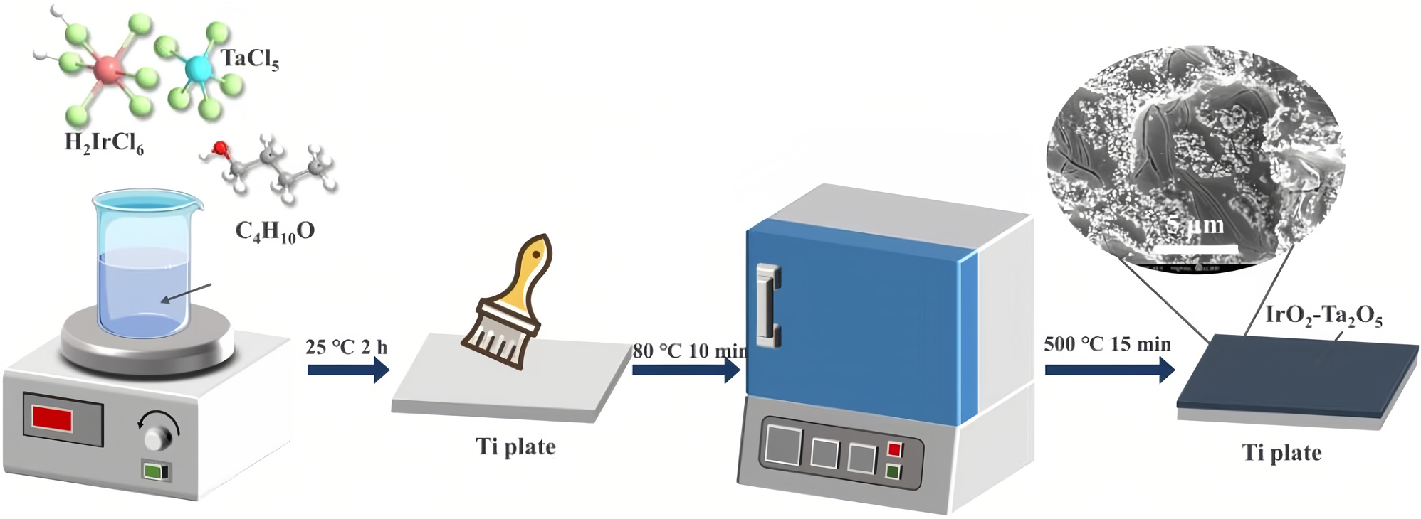
Schematic of Ti/IrO2–Ta2O5 anode preparation.
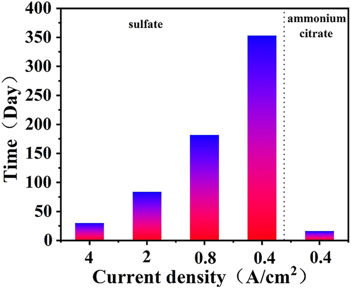
The results of IrO2–Ta2O5 anodes under different conditions during the ALT.
3.2 Crystalline phases as a function of electrolysis time
Figure 3 shows the XRD patterns of the Ti/IrO2–Ta2O5 electrode as a function of time during the ALT. Diffraction peaks corresponding to metallic Ti and rutile IrO2 are evident in the patterns of the original as well as electrolyzed anodes (Figure 3). No characteristic peaks for Ta2O5 were detected, indicating the absence of Ta2O5 crystallization during the thermal treatment of the coating. The rutile IrO2 phase was observed with (110), (101), and (211) crystal faces. The intensity of the diffraction peaks of rutile IrO2 decreased with increasing electrolysis time, but these peaks were observed in the failed anode. Thus, some residual coating remained on the anode after deactivation. The peak corresponding to metallic Ti increased with increasing electrolysis time, suggesting that the exposed area of the Ti substrate increased with increasing dissolution of the oxide coating. As indicated in the literature (Hu et al. 2002), oxidation of the Ti substrate can occur and form a TiO2 layer at the coating–substrate interface during electrolysis. However, the TiO2 phase was not observed in the entire electrolysis period, in accordance with XRD analysis. This might be attributable to the compact structure of the IrO2–Ta2O5 coating, which prevented the Ti substrate from oxidizing.
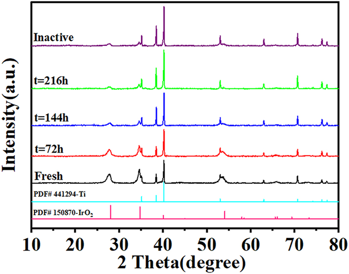
XRD patterns of the Ti/IrO2–Ta2O5 electrode as a function of electrolysis time.
3.3 Surface morphology as a function of electrolysis time
Figure 4 shows the variations of the surface morphology as a function of electrolysis time during the ALT. All of the surfaces exhibited a typical mud-crack morphological feature. Many needle-like crystals were dispersed all over the surface of the coating (Figure 4(a)). The size and quantity of the dispersed needle-like crystals decreased with increasing electrolysis time. After electrolysis for 216 h, the needle-like crystals were negligibly evident on the coating. Dissolution of the needle-like crystals decreased the quantity of active components and the active surface area for the OER, which might account for the slow increase in the potential in the ALT. Such needle-like crystals were not evident in the electrolyzed anodes because of chemical dissolution and abscission of the coating during the OER (Figure 4(c)–(j)). Increasing electrolysis time increased the quantity of pores and tracks (Alanazi et al. 2019; Hu et al. 2002; Xu et al. 2019). The porous structure of the electrolyzed coating facilitated access of the electrolyte and oxygen to the Ti substrate; resulting in less-conductive TiO2 crystals. However, the quantity of pores and tracks did not increase. This might be attributable to the compact structure of the IrO2–Ta2O5 coating, such that Ta2O5 does not react with the electrolyte.
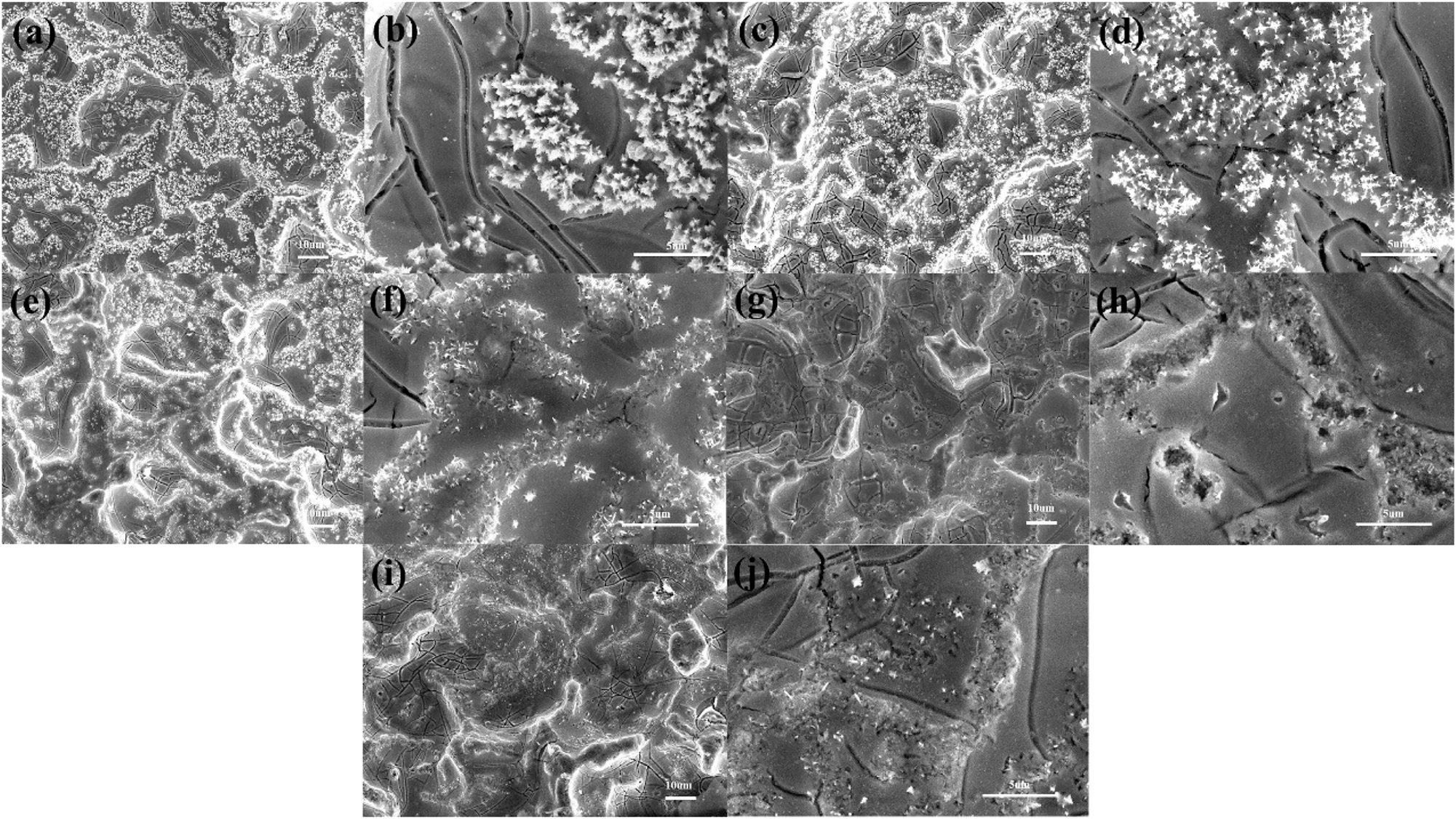
Variation of the surface morphology as a function of time during the ALT: (a), (b) original; (c), (d) t = 72 h; (e), (f) t = 144 h; (g), (h) t = 216 h; (i), (j) failed anode.
The main elemental composition of the coatings was Ti, O, Ir, and Ta (Table 1). The fresh anode atom ratio of Ir to Ta was ca. 6:4. After electrolysis for 72 h, the atom ratio of Ir to Ta was ca. 5.3:4.7. With increasing electrolysis time, the atom ratio of Ir to Ta of the coating gradually decreased, and finally stabilized at 3:7. During electrolysis, Ir reacted with the electrolyte and IrO2 was gradually dissolved, such that the ratio of Ir to Ta of the coating was gradually reduced (Figure 4).
Elemental composition of coatings, in at.%.
| Time | O | Cl | Ti | Ir | Ta |
|---|---|---|---|---|---|
| Fresh | 41.56 | 1.05 | 0.88 | 11.53 | 7.81 |
| t = 72 h | 46.99 | 0.68 | 1.24 | 8.48 | 8.03 |
| t = 144 h | 43.26 | 0.58 | 3.53 | 4.45 | 7.85 |
| t = 216 h | 38.72 | 0.37 | 4.11 | 3.41 | 7.83 |
| Inactive | 44.72 | / | 4.58 | 3.30 | 8.87 |
Figure 5 shows the EDS mapping of the surface of the original and failed anodes. Elemental Ir, Ta, Cl, and O were uniformly dispersed all over the surface of the original oxide coating (Figure 5(a)) while there was little elemental Ti on the surface. Some elemental Ir remained on the surface of the failed anode (Figure 5(b)). Some elemental Ti (the Ti substrate) was observed on the surface of the failed anode, detected by EDS because the coating was partially dissolved. Figure 6 shows the morphology of a cross section of the failed anode. The cross section was divided into two parts: the inside was comparatively denser with IrO2 crystals and the outside was comparatively less dense. The thickness of Ir on the outside of the coating was ca. 3–4 µm, and the ratio of Ir to Ta was 3:7 (area 1). There was no corrosion inside the coating, and the ratio of Ir to Ta was 6:4 (area 2). In addition, no passivation layer of nonconductive TiO2 was found in the cross section between the coating and substrate.
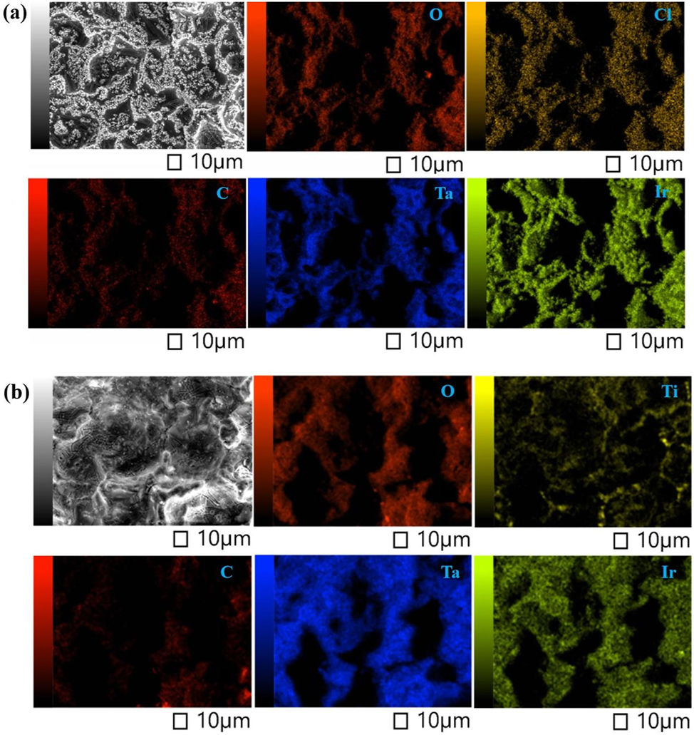
EDS mapping of the (a) original and (b) failed anodes.
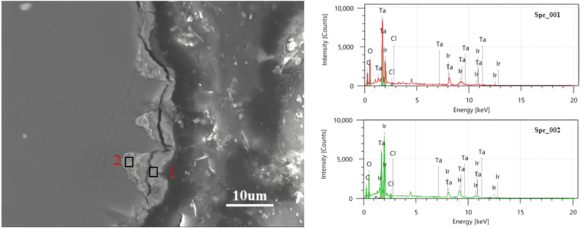
SEM and EDS of a cross section of a failed anode.
3.4 Electrochemically active surface area
Figure 7 shows CV curves of the prepared sample as a function of electrolysis time. The fresh anode exhibited a shape typical of thermally decomposed anodes (Shao et al. 2015). With increasing electrolysis time, the shape of the CV curve was almost unchanged. The peak current decreased with increasing electrolysis time. The apparent change in the voltammetric response is related to the variation of the active surface area. Because of the dissolution of IrO2, the active component was reduced and, therefore, the catalytic activity was reduced. The voltammetric charges were calculated by integrating the CV curves. This charge was considered to proportional to the number of electroactive sites, which corresponds to the electrochemically active surface area of the anode. Overall, the charge decreased with decreasing coating loading (Figure 7(b)).
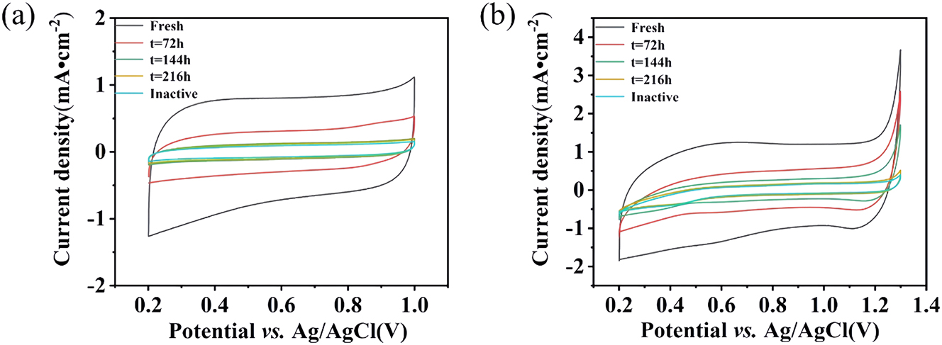
Electrochemical performance of the Ti/IrO2–Ta2O5 anode as a function of time during the ALT: (a) in aqueous ammonium citrate and (b) in aqueous sulfuric acid.
3.5 Degradation mechanism
During the ALT, samples (5 mL) were collected every 2 d for ICP–MS analysis of the dissolved elements. Figure 8 shows the concentration of Ir in solution as a function of the ALT time vs. time in 100 g/L aqueous ammonium citrate. Figure 8 also shows the cell voltage as a function of time.

Concentration of Ir in solution and the cell voltage as a function of time for the ALT in 100 g/L aqueous ammonium citrate.
The concentration of Ir increased in the first 4 days of the ALT, but afterward, the growth rate gradually decreased. In addition, Ta was not detected in the solution samples. Interestingly, throughout the ALT, ammonium citrate dissolved Ir but Ta did not react. As a result, the rate of Ir dissolution gradually decreased throughout the procedure.
To explain the aforementioned phenomenon, potential–pH diagrams were constructed to predict the dominant Ir and Ta species that are likely to be present when the coatings are exposed to ammonium citrate at various anodic potentials (Wang et al. 2020). Solid IrO2 is the thermodynamically favorable species when the potential is >0.5 V at pH 7 (Figure 9(a)). When the potential increases to >1.5 V, oxidation of IrO2 to IrO4 2− is thermodynamically favorable. Ta2O5 is the thermodynamically favorable species when the potential is >−1 V at pH 7 (Figure 9(b)).
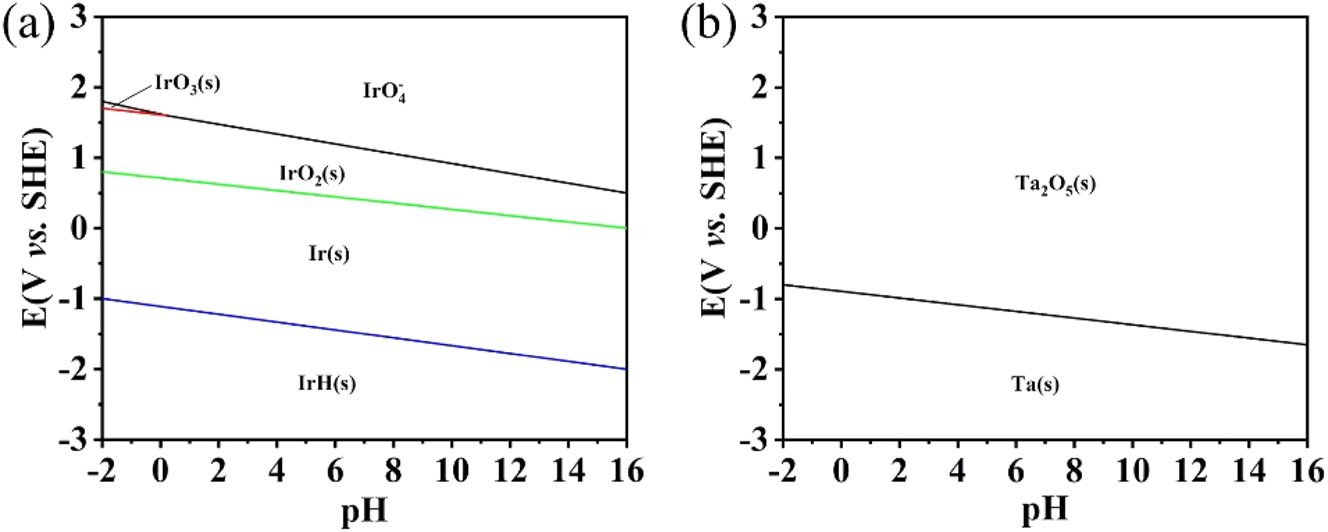
Pourbaix diagrams of Ir (a) and Ta (b) systems in aqueous ammonium citrate.
Based on the chemistry of the system and the constructed Pourbaix diagrams, it is reasonable to conclude that the following reactions occurred during the ALT tests.
Figure 10 shows a schematic for the corrosion mechanism of Ti/IrO2–Ta2O5 electrodes. As aforementioned, the stable stage is the main stage of the entire electrolysis. In this stage, the active component loaded on the coating is dissolved into the electrolyte. During this stage, the crystals are negligibly evident on the coating and the cell voltage slowly increases. The slow increase in the cell voltage is attributable to rapid dissolution of IrO2 and the reduction of the active surface area for the OER. A sharp increase in the cell voltage is observed in the sharp deactivation stage. In this stage, a large extent of dissolution of IrO2 results in the ratio of Ir to Ta in the coating reaching a critical value, and the conductivity of the coating decreases (the resistance of the original and failed anodes is 0.63 and 0.79 mΩ, respectively). Consequently, the synergistic effect of the substantial dissolution of the active components is the main reason for the failure of the Ti/IrO2–Ta2O5 anode in aqueous ammonium citrate.
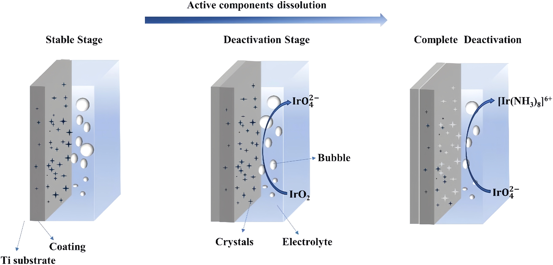
Schematic for the corrosion mechanism of Ti/IrO2–Ta2O5 electrodes in aqueous ammonium citrate.
3.6 XPS analysis
Figure 11 shows XPS spectra of the prepared sample as a function of electrolysis time. Tables 2 and 3 show the binding energy values and intensities, respectively, obtained from the height of the Ir 4f, Ta 4f, and O 1s peaks. The 4f region consisted of two distinguishable peaks, Ir 4f 7/2 and Ir 4f 5/2, with a spin–orbit splitting of 3.0 eV. Typically, the 4f region of rutile IrO2 is asymmetric because of its conductive nature (Wertheim and Guggenheim 1980). Ta 4f 7/2 was located at a binding energy of ca. 26.1 eV for all samples (Figure 10(b)), which corresponds to Ta5+ species. This value is slightly lower than 26.4 to 26.9 typically found for Ta2O5 in the literature, which can be ascribed to the nature of Ta2O5 in this IrO2–Ta2O5 oxide mixture (Xu et al. 2010). These results are in good agreement with the aforementioned XRD results. Furthermore, Figure 10(c) shows O 1s spectra of the coatings, indicating lattice oxygen (530 eV), hydroxyl groups and/or oxygen defects (531 eV), and adsorbed water (533 eV) (Wei et al. 2020). All five anodes had these three species in their coatings but with slight changes in binding energy, possibly because of the difference in Ir/Ta ratio. The intensity of the 4f 5/2 and 4f 7/2 peaks corresponding to Ir decreased during the ALT, suggesting that Ir was removed from the solid. Regarding Ta, the intensity of these peaks decreased only slightly. These results are in good agreement with the aforementioned Pourbaix diagram results.
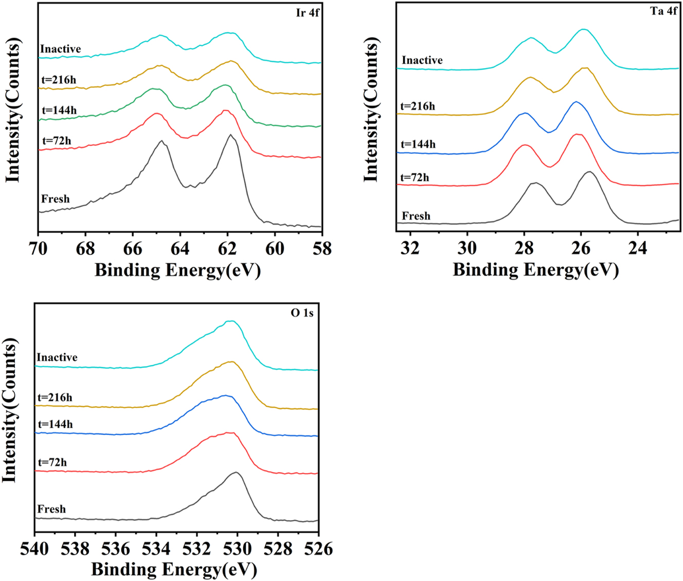
XPS spectra of Ir 4f (a), Ta 4f (b), and O 1s (c) levels as a function of time during the ALT.
Binding energy for Ir 4f, Ta 4f, and O 1s peaks in various samples.
| Sample | Binding energy(ev) | ||||
|---|---|---|---|---|---|
| Ir | Ta | O | |||
| 4f5/2 | 4f7/2 | 4f5/2 | 4f7/2 | 1s | |
| Fresh | 64.77 | 61.87 | 27.57 | 25.67 | 530.07 |
| t = 72 h | 64.97 | 62.07 | 27.97 | 26.17 | 530.57 |
| t = 144 h | 65.07 | 62.07 | 27.97 | 26.17 | 530.57 |
| t = 216 h | 64.77 | 61.87 | 27.77 | 25.77 | 530.27 |
| Inactive | 64.87 | 61.97 | 27.77 | 25.97 | 530.27 |
Intensity for Ir 4f, Ta 4f, and O 1s peaks in various samples.
| Sample | Intensity (counts) | ||||
|---|---|---|---|---|---|
| Ir | Ta | O | |||
| 4f5/2 | 4f7/2 | 4f5/2 | 4f7/2 | 1s | |
| Fresh | 9,588 | 11,125 | 12,767 | 16,183 | 30,340 |
| t = 72 h | 5,782 | 6,798 | 12,685 | 16,014 | 25,142 |
| t = 144 h | 4,848 | 5,675 | 12,698 | 16,219 | 24,944 |
| t = 216 h | 3,161 | 4,043 | 11,710 | 14,597 | 29,212 |
| Inactive | 2,992 | 3,621 | 9,952 | 12,482 | 30,136 |
4 Suggested solutions
There is a technique to control or solve the problem caused by IrO2 was gradually dissolved. Through the construction of core–shell structure, the direct contact between IrO2 and the electrolyte ammonium citrate is reduced, and the dissolution rate of IrO2 is reduced. The stability is doubled under the same load of precious metal. However, due to the existence of commercial secrets in this technology, it is not convenient to disclose.
5 Conclusions
The corrosion mechanism of Ti/IrO2–Ta2O5 anodes in aqueous ammonium citrate solution was investigated by physical characterizations and electrochemical analysis. The slow increase in the cell voltage in the slow deactivation stage was attributable to substantial dissolution of IrO2 and a decrease of the active surface area. EDS analysis indicates that the molar ratio of Ir to Ta in the coating changed during the ALT. The Ir to Ta ratio stabilized at 3:7. However, during this time, no passivation layer of nonconductive TiO2 was found in a cross section between the coating and substrate. Consequently, the corrosion mechanism of the compact IrO2–Ta2O5 coating is the synergistic effect of substantial dissolution of the active components.
-
Research ethics: Not applicable.
-
Informed consent: Not applicable.
-
Author contributions: The authors have accepted responsibility for the entire content of this manuscript and approved its submission.
-
Use of Large Language Models, AI and Machine Learning Tools: None declared.
-
Conflict of interests: The authors state no conflict of interest.
-
Research funding: This research did not receive any specific grant from funding agencies in the public, commercial, or not-for-profit sectors.
-
Data availability: Not applicable.
References
Abdulgani, I., Escalona-Durán, F., De Araújo, D.M., Dos Santos, E.V., Segundo, I.D.B., and Martínez-Huitle, C. (2022). The role of saline-related species in the electrochemical treatment of produced water using Ti/IrO2-Ta2O5 anode. J. Electroanal. Chem. 910: 1–8, https://doi.org/10.1016/j.jelechem.2022.116163.Suche in Google Scholar
Alanazi, N.M., Al-Abdulhadi, A.I., Al-Zharani, T.Y., Al-Khaldi, T.A., Alghamdi, R.A., Al-Shaikh Ali, A.H., and Shen, S. (2019). Electrochemical properties of IrO2-Ti2O5-Co3O4 coated Ti anode in acid media. Surf. Coat. Technol. 374: 815–821, https://doi.org/10.1016/j.surfcoat.2019.06.059.Suche in Google Scholar
Asoh, H., Nakamura, K., and Ono, S. (2007). Control of pit initiation sites on aluminum foil using colloidal crystals as mask. Electrochim. Acta 53: 83–86, https://doi.org/10.1016/j.electacta.2007.01.021.Suche in Google Scholar
Ban, C., He, Y., Shao, X., and Wang, Z. (2014). Effects of polymer corrosion inhibitor on widening etch tunnels of aluminum foil for capacitor. Corros. Sci. 78: 7–12, https://doi.org/10.1016/j.corsci.2013.07.011.Suche in Google Scholar
Comninellis, C. and Vercesi, G.P. (1991). Characterization of DSA-type oxygen evolving electrodes: choice of a coating. J. Appl. Electrochem. 21: 335–345, https://doi.org/10.1007/bf01020219.Suche in Google Scholar
Deng, L., Liu, Y., Zhao, G., Chen, J., He, S., Zhu, Y., Chai, B., and Ren, Z. (2019). Preparation of electrolyzed oxidizing water by TiO2 doped IrO2-Ta2O5 electrode with high selectivity and stability for chlorine evolution. J. Electroanal. Chem. 832: 459–466, https://doi.org/10.1016/j.jelechem.2018.11.047.Suche in Google Scholar
Du, X., Lin, B., Li, B., Feng, T., Mao, S., and Xu, Y. (2017). Surface modification of Al foils for aluminum electrolytic capacitor. Adv. Funct. Mater. 27: 1–8, https://doi.org/10.1002/adfm.201606042.Suche in Google Scholar
Geiculescu, A.C. and Strange, T.F. (2003). Characterization of crystalline alumina films formed in alcohole-water solutions. Thin Solid Films 445: 105–111, https://doi.org/10.1016/s0040-6090(03)01194-5.Suche in Google Scholar
Hou, Z., Zeng, J., Chen, J., and Liao, S. (2010). Ultrasonic-assisted ac etching of aluminum foils for electrolytic capacitor electrodes with enhanced capacitance. Mater. Chem. Phys. 123: 625–628, https://doi.org/10.1016/j.matchemphys.2010.05.027.Suche in Google Scholar
Hu, J., Meng, H., Zhang, J., and Cao, C. (2002). Degradation mechanism of long servicelife Ti/IrO2-Ta2O5 oxide anodes in sulphuric acid. Corros. Sci. 44: 1655–1668, https://doi.org/10.1016/s0010-938x(01)00165-2.Suche in Google Scholar
Lee, J., Kang, D., Lee, K., and Chang, D. (2011). An investigation on the electrochemical characteristics of IrO2-Ta2O5 anodes for the application of electrolysis process. Mater. Sci. Appl. 2: 237–243.10.4236/msa.2011.24030Suche in Google Scholar
Li, B., Lin, A., and Gan, F. (2006). Preparation and electrocatalytic properties of Ti/IrO2-Ta2O5 anodes for oxygen evolution. Trans. Nonferrous Met. Soc. China. 16: 1193–1199, https://doi.org/10.1016/s1003-6326(06)60400-7.Suche in Google Scholar
Liang, L., He, Y., Song, H., Yang, X., and Cai, X. (2014). Effect of placement of aluminium foil on growth of etch tunnels during DC etching. Corros. Sci. 79: 21–28, https://doi.org/10.1016/j.corsci.2013.10.017.Suche in Google Scholar
Liu, B., Ma, B., Chen, Y., and Wang, C. (2020). Corrosion mechanism of Ti/IrO2-RuO2-SiO2 anode for oxygen evolution in sulfuric acid solution. Corros. Sci. 170, https://doi.org/10.1016/j.corsci.2020.108662.Suche in Google Scholar
Ma, D., Ngo, V., Raghavan, S., and Sanfoval, S. (2016). Degradation of Ir-Ta oxide coated Ti anodes in sulfuric acid solutions. Corros. Sci. 164, https://doi.org/10.1016/j.corsci.2019.108358.Suche in Google Scholar
Morimitsu, M., Murakami, C., Kawaguchi, K., Otogawa, R., and Matsunaga, M. (2004). Stability of iridium oxide-tantalum oxide coated titanium electrodes for oxygen evolution in alkaline solutions. J. New Mater. Electrochem. Syst. 7: 323–327.Suche in Google Scholar
Shao, Y., Yi, Z., He, C., Zhu, J., and Tang, D. (2015). Effects of annealing temperature on the structure and capacitive performance of nanoscale Ti/IrO2-ZrO2 electrodes. J. Am. Ceram. Soc. 98: 1485–1492, https://doi.org/10.1111/jace.13475.Suche in Google Scholar
Wang, Y., Zhang, M., Kang, Z., Shi, L., Shen, Y., Tian, B., Zou, Y., Chen, H., and Zou, X. (2023). Nano-metal diborides-supported anode catalyst with strongly coupled TaOx/IrO2 catalytic layer for low-iridium-loading proton exchange membrane electrolyzer. Nat. Commun. 14: 2–12, https://doi.org/10.1038/s41467-023-40912-8.Suche in Google Scholar PubMed PubMed Central
Wang, Z., Guo, X., Montoya, J., and Nørskov, J.K. (2020). Predicting aqueous stability of solid with computed Pourbaix diagram using SCAN functional. npj Comput. Mater. 6: 160, https://doi.org/10.1038/s41524-020-00430-3.Suche in Google Scholar
Wei, Z., Kang, X., Xu, S., Zhou, X., Jia, B., and Feng, Q. (2020). Electrochemical oxidation of Rhodamine B with cerium and sodium dodecyl benzene sulfonate co-modified Ti/PbO2 electrodes: preparation, characterization, optimization, application. Chin. J. Chem. Eng. 32: 191–202, https://doi.org/10.1016/j.cjche.2020.09.044.Suche in Google Scholar
Wertheim, G.K. and Guggenheim, H.J. (1980). Conduction-electron screening in metallic oxides: IrO2. Phys. Rev. B 2: 4680–4683, https://doi.org/10.1103/physrevb.22.4680.Suche in Google Scholar
Xiao, R., Yan, K., Yan, J., and Wang, J. (2008). Electrochemical etching model in aluminum foil for capacitor. Corros. Sci. 50: 1576–1583, https://doi.org/10.1016/j.corsci.2008.02.017.Suche in Google Scholar
Xin, Y., Xu, L., Wang, J., and Li, X. (2010). Effect of sintering temperature on microstructure and electrocatalytic properties of Ti/IrO2-Ta2O5 anodes by Pechini method. Rare Metal Mater. Eng. 39: 1903–1907, https://doi.org/10.1016/s1875-5372(10)60135-x.Suche in Google Scholar
Xu, C., Qiang, Y., Zhu, Y., Guo, L., Shao, J., and Fan, Z. (2010). Laser damage mechanisms of amorphous Ta2O5 films at 1064, 532 and 355 nm in one-on-one regime. Chin. Phys. Lett. 27, https://doi.org/10.1088/0256-307x/27/11/114205.Suche in Google Scholar
Xu, G., Peng, N., Wang, P., and Xiao, Y. (2022). Effect of bipolar electrochemical process on tunnel etching characteristics of aluminum Foil. J. Electrochem. Soc. 3: 169.10.1149/1945-7111/ac4e54Suche in Google Scholar
Xu, L. and Scantlebury, J.D. (2003). A study on the deactivation of an IrO2-Ta2O5 coated titanium anode. Corros. Sci. 45: 2729–2740, https://doi.org/10.1016/s0010-938x(03)00108-2.Suche in Google Scholar
Xu, L., Xin, Y., and Wang, J. (2009). A comparative study on IrO2-Ta2O5 coated titanium electrodes prepared with different methods. Electrochim. Acta 54: 1820–1825, https://doi.org/10.1016/j.electacta.2008.10.004.Suche in Google Scholar
Xu, W., Haarberg, G.M., Sunde, S., Seland, F., Ratvik, A.P., Zimmerman, E., Shimamune, T., Gustavsson, J., and Åkred, T. (2017). Calcination temperature dependent catalytic activity and stability of IrO2-Ta2O5 anodes for oxygen evolution reaction in aqueous sulfate electrolytes. J. Electrochem. Soc. 164: F895–F900, https://doi.org/10.1149/2.0061710jes.Suche in Google Scholar
Xu, W., Haarberg, G.M., Seland, F., Sunde, S., Ratvik, A.P., Holmin, S., Gustavsson, J., Afvander, Å., Zimmerman, E., and Åkre, T. (2019). The durability of the thermally decomposed IrO2-Ta2O5 coated titanium anode in a sulfate solution. Corros. Sci. 150: 76–90, https://doi.org/10.1016/j.corsci.2019.01.018.Suche in Google Scholar
Zhang, Y., Cao, M., Lv, H., Wei, J., Gu, Y., Liu, D., Zhang, W., Ryan, M.P., and Wu, X. (2018). Electrodeposited nanometer-size IrO2/Ti electrodes with 0.3 mg IrO2 cm-2 for sludge dewatering electrolysers. Electrochim. Acta 265: 507–513, https://doi.org/10.1016/j.electacta.2018.01.190.Suche in Google Scholar
© 2025 the author(s), published by De Gruyter, Berlin/Boston
This work is licensed under the Creative Commons Attribution 4.0 International License.
Artikel in diesem Heft
- Frontmatter
- Reviews
- Why is the modified wedge-opening-loaded test inadequate for characterizing gaseous hydrogen embrittlement in pipeline steels? A review
- Research progress on zirconium alloys: applications, development trend, and degradation mechanism in nuclear environment
- Original Articles
- Effect of seawater intrusion in water-glycol hydraulic fluid on the electrochemical corrosion behavior of carbon steel and stainless steel
- Durability of a thermally decomposed iridium(IV) oxide–tantalum(V) oxide coated titanium anode in aqueous ammonium citrate
- Microscopic analysis of the destruction of passive film on stainless steel caused by sulfide in simulated cooling water