The effect of Pd and Ni coatings on hydrogen permeation experiments of as-quenched martensitic steel
-
Renata Latypova

 ,
Tun Tun Nyo
,
Tun Tun Nyo

Abstract
Hydrogen permeation technique is a widely used testing method for the determination of hydrogen diffusion coefficient (D), which is an important parameter considering hydrogen embrittlement. A palladium (Pd) or nickel (Ni) coating is often utilised on the hydrogen detection side of the test specimens. Here, we investigate the effect of Pd and Ni coatings on hydrogen diffusion in a martensitic 500 HBW hardness low-alloy steel in the thickness range of 0.5 – 0.8 mm using a refined successive transient method and compare against an uncoated reference specimen. Both coatings yield similar average D values (6 – 6.6 × 10⁻⁷ cm2/s), but the best repeatability is achieved with Pd coating. With Ni coating, D values decrease with the increasing specimen thickness, which is partly caused by a slower hydrogen diffusion in Ni, and therefore a concentration gradient at the specimen-coating interface. The uncoated specimen has a poor transient fit, and significantly lower D (2.1 × 10⁻⁷ cm2/s) due to surface oxidation. With both coatings, the steepness of the last decay transient was highly affected by specimen thickness, and therefore the density of reversible hydrogen traps is only comparable for similar thicknesses.
1 Introduction
Hydrogen permeation test is a sensitive electrochemical technique that has been utilized for over 60 years (Devanathan and Stachurski 1962). There are currently two standards describing this test method for studying the hydrogen uptake, permeation, and transport in metals. According to these standards, the effective diffusion coefficient (D), i.e., diffusion coefficient that is affected by hydrogen trapping, can be calculated with a time-lag method or a breakthrough time method (American Society for Testing and Materials 2003, Finnish Standards Association 2014). Both methods focus on one rising permeation transient, and they are widely used due to their simplicity. Other methods, such as successive transient method and refined successive transient method, utilise additional decay and build-up curves after the prior transient (time-lag/breakthrough method), i.e., after reaching a steady-state (Liu et al. 2016). In addition to the hydrogen diffusion coefficient, hydrogen permeation test can be used to calculate subsurface hydrogen concentration, and to evaluate the density of reversible hydrogen traps (Mallick et al. 2021; Venezuela et al. 2018). The effect of irreversible traps can also be studied with consecutive permeation-desorption transients (Kim et al. 2014).
Hydrogen permeation test setup consists of two opposite cells with a specimen clamped between them. One cell is used for hydrogen charging, which can be done electrochemically or with gaseous charging, and the other cell is used for hydrogen detection. It is recommended to coat the detection side of the specimen with palladium (Pd) or nickel (Ni) to prevent specimen oxidation, minimize variations in surface conditions, and to increase the efficiency of the hydrogen atom oxidation reaction for more repeatable data (Manolatos et al. 1995; ASTM G148 – 97 2003; SFS-EN ISO 17081 2014). In addition to coating, specimen thickness has an important role in the permeation experiments. With too thin membranes, hydrogen diffusion may not be volume controlled, but affected by surface reactions. The critical thickness for volume-controlled diffusion is not universal but depends on the selected test environment and material (Kittel et al. 2008). Therefore, it is important to determine the critical thickness, which can be utilised for analysis in each test set-up.
Both Pd (Rudomilova et al. 2020; Svoboda et al. 2014; Venezuela et al. 2016) and Ni (Akiyama and Li 2016; Du et al. 2019; Kim et al. 2014) coatings are commonly utilised in hydrogen permeation experiments. Even uncoated specimens have been successfully used with the time-lag method (Depover and Verbeken 2016; Van den Eeckhout et al. 2018). However, Pd coating is generally seen as essential in hydrogen permeation experiments. Without coating, hydrogen oxidation is not sufficient and molecular hydrogen has time to form and escape detection. Hydrogen oxidation occurs more readily on the Pd surface, ensuring the reliability of the measurements (Manolatos et al. 1995).
Pd is more noble metal in comparison to Ni, but it is also significantly more expensive which makes it less desirable solution. Also, hydrogen diffusion is significantly faster in Pd than in Ni: reported D values with hydrogen permeation technique are in magnitude of 10−10 cm2/s for Ni (Latanision and Kurkela 1983), and 10−7 cm2/s for Pd (Devanathan and Stachurski 1962). In this study, we utilise the refined successive transient method with specimens coated with Pd or Ni on the exit side to quantify the comparability of the different coating types, using an uncoated specimen as a reference.
2 Materials and methods
2.1 Test materials
A direct-quenched (DQ) steel with an auto-tempered lath-martensitic microstructure (Figure 1) was utilised in hydrogen permeation experiments. The chemical composition in wt% and tensile properties such as 0.2 % offset yield stress (YS), tensile strength (TS) and measured hardness of DQ steel are presented in Table 1.

FESEM images of (a) lath-martensitic microstructure and (b) coarse auto-tempered region of DQ steel.
Chemical composition (wt%), balance Fe, and mechanical properties of DQ steel.
| Steel | C | Si | Mn | YS (MPa) | TS (MPa) | Hardness (HBW) |
|---|---|---|---|---|---|---|
| DQ | 0.25 | 0.1 | 0.25 | 1411 | 1632 | 484 (±3) |
Permeation specimens with ∼1 mm thickness were ground and mechanically polished with 3 µm diamond suspension to achieve a mirror surface on both specimen sides. The final specimen thickness varied between 0.48 and 0.84 mm. One side of the specimen was then electroplated with palladium (Pd) or nickel (Ni) using commercial plating baths, aiming to get an approximately 1 µm coating thickness. Both electroplating solutions were accompanied by a calculator that estimated the necessary current density for the desired thickness based on the specimen surface area (SPA Plating 2017, 2018). For each coating type, 5 – 6 permeation experiments were conducted, and one test in the uncoated condition as the reference.
2.2 Hydrogen permeation
Electrochemical permeation (EP) tests were conducted at room temperature with a Devanathan-Stachurski cell, which was designed following the existing standards. The specimen radius (r) exposed to the solution is 11 mm (Figure 2a), and therefore the ratio of radius to thickness is more than 10:1 (ASTM G148 – 97 2003; SFS-EN ISO 17081 2014). The cell material is PVC, which is considered inert to the test environment of 0.1 M NaOH used on both sides of the cell. The left side of the cell is used for hydrogen charging (entry) and the right side for hydrogen detection (exit), while the specimen is clamped between the cells acting as a working electrode (WE), Figure 3.

Permeation cell presented from two view angles. (a) Side view of the cell with dimensions in mm and (b) general view of the left side cell.
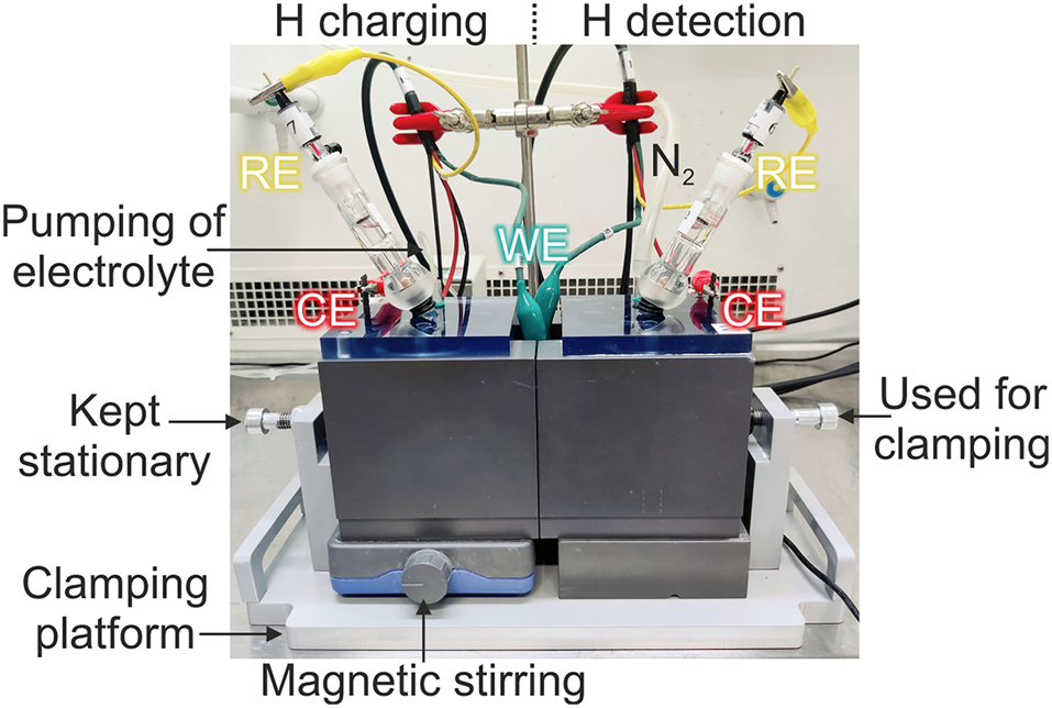
Hydrogen permeation test set-up.
To avoid air gaps and corrosion due to trapped hydrogen bubbles on the specimen surface from hydrogen charging, the inner diameter exposed to the solution increases towards the main cell (Figure 2a). For easy clamping, on the left side of the cell, two rods are added where the specimen is first placed (Figure 2b). On the opposite side, there are holes where the rods slide in when the cells are pushed together. Afterwards, both cells and the specimen between them are moved to a clamping platform (Figure 3). The cells are pressed together from the right side, while the left side has only stationary support. The sealing of the specimen is assured with removable O-rings.
Cells also have removable covers with holes for electrodes, nitrogen bubbling and pumping of the electrolyte (Figure 3). In both cells, a mixed metal oxide (MMO) mesh surrounds the inner walls of the cell acting as a counter electrode (CE), and Hg/HgO reference electrodes placed in Luggin capillary are used as reference electrodes (RE). The electrolyte on the left side of the cell is constantly mixed and the de-aerated electrolyte is pumped to the bottom of the cell at a rate of 3.5 ml/min. At the top of the left cell is an outlet where the electrolyte flows over to maintain the same level throughout the test. On the right side, constant N2 bubbling is used inside the cell.
During the test, a two-channel Corrtest CS2150 Bipotentiostat is used to apply constant potential on both sides. The permeation test steps are presented in Table 2. At the beginning of each test, the right side is polarized with 0.3 V until the permeation current is below 0.3 μA/cm2. Meanwhile, the left side cell has N2 bubbling to protect the freshly polished uncoated specimen surface. When the permeation current is low enough, the left side is filled with the electrolyte, and hydrogen pre-charging (12 h) is started with −1.2 V. After pre-charging, 4 transients with 2 h per transient are completed by lowering the hydrogen charging potential to −1.1 V and back to −1.2 V twice. As the last part of the test, the left side is polarized with 0.3 V (2 h) until complete decay. On the right side of the cell, the permeation current density is recorded as a function of time. Hydrogen charging potentials were selected based on the electrochemical polarisation curve measured for the DQ steel (Figure 4).
Permeation test steps on the entry and exit sides of the test system.
| Entry side | Exit side | ||
|---|---|---|---|
| Step 1 | Passivation | N2 bubbling (inert environment) | Introduction of electrolyte |
| Apply: E = 0.3 V, Until permeation current is less than 0.3 μA/cm2 |
|||
| Pre-charging | Introduction of electrolyte | Apply: E = 0.3 V, up to steady state | |
| Apply E = −1.2 V (12 h) | |||
| Step 2 | Decay 1 & 2 | Apply E = −1.1 V (2 h/step) | Apply: E = 0.3 V, down to steady state |
| Build-up 1 & 2 | Apply E = −1.2 V (2 h/step) | Apply: E = 0.3 V, up to steady state | |
| Step 3 | Complete decay | Apply E = 0.3 V (2 h), down to total discharge | Apply E = 0.3 V, down to total discharge |

Electrochemical polarization curve of DQ in 0.1 M NaOH solution at room temperature.
From each test, 4 hydrogen diffusion coefficients (D) and the density of reversible traps (NT) are calculated. D is determined from the decay and build-up transients using the following build-up Equation (1) and decay Equation (2) equations:
where L = specimen thickness, ip = measured permeation rate at time t,
During complete decay, it is assumed that the reversible traps are emptied and therefore NT can be evaluated using the area difference (A) between the experimental curve and the theoretical decay curve fitted with DL (Zakroczymski 2006; Liu and Atrens 2015; Mallick et al. 2021; Rudomilova et al. 2020). NT (sites/cm3) is calculated with the following equation:
where A = area difference between the complete decay and theoretical permeation transient fitted with DL (As/cm2), L = specimen thickness (cm) and 6.24 × 10¹⁸ is the number of hydrogen traps (1 C = 1 As = 6.24 × 10¹⁸ e) (Liu and Atrens 2015).
After permeation experiments, specimen surfaces were inspected visually. The coating thicknesses of Pd and Ni were studied with cross-sections of the specimens using a Zeiss Sigma field-emission scanning electron microscope (FESEM).
3 Results and discussion
3.1 Electrochemical polarization
To select the appropriate cathodic potential for hydrogen charging in the permeation experiments, electrochemical polarisation curve was measured between −1.6 V and 1 V (Figure 4). DQ steel shows cathodic Tafel behaviour to approximately −0.45 V, and thus the selected potential level −1.2 to −1.1 V is well in the range for hydrogen charging.
3.2 Coating
The coating thickness was investigated from three locations from the tested specimens: the opposite edges and the centre of the specimen. The average coating thickness is 1.1 ± 0.05 µm for Pd and 0.6 ± 0.07 µm for Ni coating based on 20 measurement points/coating. Figure 5 presents an example of cross-section specimens with the marked average thickness for each coating type.

Cross-sections of Pd and Ni coated specimens.
Noble Pd coating on the hydrogen detection side did not gain any discolouring in the tests, indicating that it is sufficiently inert in the given conditions. In contrast, both less noble Ni coating and the surface of the uncoated specimen have clearly visible circular oxidized region where the electrolyte was in contact with the specimen. In contrast-enhanced Figure 6, specimen surfaces on hydrogen detection side are presented with black arrows pointing at the edges of the circular oxidation regions.

Specimen surfaces on hydrogen detection side after permeation experiments. Specimen height is 4 cm.
3.3 Permeation curves
All the produced hydrogen permeation curves are presented in Figure 7. When similar specimen thicknesses are compared, the permeation current density is lowest for the uncoated specimen, and it increases with Ni coating, and further with Pd coating. This increase can be explained by formation and growth of a passive layer (Figure 6), which acts as a diffusion barrier. Without coating, some hydrogen atoms can also recombine into molecules, which are not measured leading to reduced permeation current density (Manolatos et al. 1995; Svoboda et al. 2014). Higher current densities with Pd coating in comparison to the uncoated detection surface have been previously reported for Armco iron and X70T steel as well (Manolatos et al. 1995; Samanta et al. 2020). Also, hydrogen diffusion is significantly lower in Ni than in Pd, which influences the detected current densities.

Hydrogen permeation curves.
The aim of the permeation measurements is to have volume/bulk-controlled diffusion to enable analysis of the permeation transients based on one-dimensional diffusion (ASTM G148 – 97 2003; SFS-EN ISO 17081 2014). Hydrogen atom transport is considered bulk controlled when the steady-state current density (Iss) and reciprocal thickness have a linear correlation (Dean 2005; Kittel et al. 2008; Kim and Kim 2017). Figure 8 presents the obtained current densities (12 h) plotted against the reciprocal thickness of each coated specimen. Initially, Ni coated specimens have poor linear correlation (R2 = 0.6), which indicates that hydrogen diffusion is controlled also by surface processes. However, correlation improves up to R2 = 0.81 with the removal of the thinnest 0.66 mm specimen. Pd coating has a good linear correlation, but the thinnest specimen (0.48 mm) has poor build-up and decay transient stability in comparison to the thicker specimens. With the thinnest specimen, the permeation current density gradually decreases/rises after each build-up/decay (Figure 7).

Linear correlation between Iss and 1/L.
It appears that the critical thickness for the volume-controlled diffusion is considerably higher for the Ni coated than for the Pd coated specimens. All results from Pd coating are utilized in the further analysis, but with Ni coating the result of the 0.66 mm specimen is not considered, since it may have been influenced by unwanted surface processes.
3.4 Diffusion coefficients
Examples of the obtained build-up and decay curves with fitted curves for Pd and Ni coated as well as uncoated specimens are presented in Figure 9. For Pd and Ni coatings, the curves are repeatable and reproducible with a good overlapping fit for all 4 transients. The uncoated reference specimen has a poor fit in comparison to the coated specimens, and therefore it cannot be used for a reliable calculation of D.

Normalised build-up (1 & 2) and decay (1 & 2) transients with fitted curves.
For Pd and Ni coated specimens, D results are analysed based on the specimen thickness (Figure 10a), and by plotting all D values (Figure 10b). The average D is 6.0 × 10⁻⁷ ± 5.9 × 10⁻⁸ cm2/s for Ni coated specimens and 6.6 × 10⁻⁷ ± 9.6 × 10⁻⁹ cm2/s for Pd coated specimens. Slightly slower D = 4.3 × 10⁻⁷ cm2/s results have been published for Pd-coated predominantly martensitic MS1700 steel with a marginally higher carbon content of 0.27 wt% C than in this study, also determined with a refined successive transient method (Venezuela et al. 2020).

All D results presented (a) according to the specimen thickness and (b) combined for each coating type.
The poor-fitted uncoated reference specimen has a slower average D of 2.1 × 10⁻⁷ cm2/s. Pronounced passive layer (Figure 6) explains this slower diffusion with possible hydrogen recombination on the detection side. The average D for Pd and Ni coatings are comparable, but D trends for the two coating types are significantly different depending on the specimen thicknesses. Pd specimens have even results for all thicknesses, while the obtained D values of the Ni coated specimens are strongly dependent on the specimen thickness, decreasing with increasing specimen thickness. However, in the specimen thickness range of 0.69 – 0.75 mm, D is similar for both coating types.
Hydrogen diffusion in the martensitic DQ steel and Pd is of the same magnitude (10−7 cm2/s), which means that Pd should not retard diffusion (Devanathan and Stachurski 1962). In Ni, D is several orders slower than in Fe-martensite, likely creating a concentration gradient at the steel-Ni interface. With thicker specimens, the gradient will become more severe since more hydrogen is diffusing to the interface. It is possible that the build-up of hydrogen will lead to a partial coating delamination, and therefore not all hydrogen is detected, leading to a slower diffusion in the thicker specimens.
For this type of steel, Pd and Ni coatings are comparable only in a small thickness range with Pd coating producing more consistent data. Hydrogen permeation experiments for similar microstructures as martensitic DQ steel benefit more from Pd coating than Ni coated or uncoated condition. Pd coating does not retard H diffusion, and a wider range of specimen thicknesses can be utilised. The thicker specimens have the best stability, and too thin specimens can lead to less stable transients also with Pd coating. Therefore, the specimen thickness should be close to the maximum thickness that can be used with the designed surface area of the cell (L ∼ 1/10r). Potentially, Ni coating can be used for the permeation experiments of materials with significantly lower D, such as austenitic stainless steels. Then, diffusion through Ni will not be the limiting factor. It is also possible that a thinner Ni coating could provide more repeatable data with martensitic steels.
3.5 Hydrogen trapping
The density of reversible hydrogen traps is calculated with the highest D value obtained from each test, i.e., with DL. Figure 11a presents all NT results, and Figure 11b, c shows an example of the determined surface area between the test data and theoretical curve fitted with DL. The obtained results are mainly in the magnitude of 1019, except with the thinnest 0.48 mm specimen, which yields a higher trapping site density of 1020 sites/cm3.

All NT results presented (a) according to the specimen thickness with (b, c) examples of determined A used in NT calculations.
The results show that NT determined this way decreases with the increasing specimen thickness, which could seem controversial. However, this is most likely resulting from mathematical reasons related to calculation of A. For thinner specimens, the complete decay curve is steeper (Figure 11b) than for thicker specimens (Figure 11c), but similar DL (6.53 – 6.74 × 10⁻⁷ cm2/s) are used for calculation of the theoretical decay curves. This leads to bigger A and A/L in thinner specimens and subsequently higher NT results.
For all specimens, sufficient grinding and polishing has been conducted prior to testing. With thinner specimens, the surface that has been affected by the preparation is more significant than in the thicker specimens. This higher ratio of preparation-affected surface can also contribute to higher trapping in thinner specimens. However, this factor could not be quantified in this study.
For Pd (0.74 mm) and Ni (0.75 mm) specimens, the NT results are similar, same as with D. As NT results deviate a lot even for the same material depending on the thickness, it is advisable to compare only specimens with the same thickness with this type of NT calculation when studying different microstructures.
4 Conclusions
We conducted hydrogen permeation experiments with an ultrahigh-strength direct-quenched (DQ) martensitic steel with different specimen thicknesses (0.48 – 0.84 mm) and surface conditions on the detection side: Pd coated, Ni coated, and uncoated. The successive transient method was used for results analysis, and 4 diffusion coefficients (D) and the density of reversible traps (NT) were calculated from each test. The main goal was to determine the effect of different coatings and how comparable they are within the sample thickness range. The following conclusions are:
Surface oxidation on the detection side is neglectable in Pd coatings and is more severe in Ni coated and uncoated specimens, lowering the detected current densities.
The uncoated DQ specimen has average D = 2.1 × 10⁻⁷ cm2/s but has poor transient fit, and therefore cannot be reliably used with the refined successive transient method. Ni coated specimens have a good transient fit with average D = 6 × 10⁻⁷ cm2/s in the specimen thickness range of 0.66 – 0.83 mm. However, data is not repeatable as D decreases with increasing specimen thickness. Pd coated specimens have very good transient fits with average D = 6.6 × 10⁻⁷ cm2/s and repeatable results in the specimen thickness range of 0.48 – 0.84 mm.
Pd coating provides better repeatability in comparison to Ni coating. Hydrogen diffusion in martensitic DQ steel and Pd is in the same magnitude (10−7), while in Ni it is considerably slower (10−10). Slower diffusion and pronounced surface oxidation in Ni lead to an increasing hydrogen concentration gradient at the specimen-coating interface.
NT is highly affected by the specimen thickness and only specimens with similar thicknesses should be compared with given method.
Funding source: Academy of Finland
Award Identifier / Grant number: #337108
Funding source: Business Finland
Funding source: Business Finland
Award Identifier / Grant number: Unassigned
Funding source: Academy of Finland
Award Identifier / Grant number: Unassigned
Acknowledgments
The authors wish to thank the technical staff of the Materials and Mechanical Engineering unit at the University of Oulu. The design work of the permeation test set-up by Kasper Hahtonen, manufacturing of the cells and clamping system by Tapani Mäntykenttä and Jari Ulkuniemi as well as specimen preparation by Jorma Mäkitalo are highly appreciated.
-
Author contributions: All the authors have accepted responsibility for the entire content of this submitted manuscript and approved submission.
-
Research funding: The authors gratefully acknowledge funding from Business Finland Oy (Project FOSSA– Fossil-Free Steel Applications) and Academy of Finland (#337108).
-
Conflicts of interest: The authors declare no conflicts of interest regarding this article.
References
Akiyama, E. and Li, S. (2016). Electrochemical hydrogen permeation tests under galvanostatic hydrogen charging conditions conventionally used for hydrogen embrittlement study. Corros. Rev. 34: 103–112, https://doi.org/10.1515/corrrev-2015-0049.Search in Google Scholar
American Society for Testing and Materials (2003). Standard practice for evaluation of hydrogen uptake, permeation, and transport in metals by an electrochemical technique (ASTM G148-97). ASTM International, West Conshohocken.Search in Google Scholar
Dean, F.W.H. (2005). Measurement of hydrogen permeation through structural steel sections of varying thickness at 19°C. Mater. Sci. Technol. 21: 347–351, https://doi.org/10.1179/174328405x29212.Search in Google Scholar
Depover, T. and Verbeken, K. (2016). Hydrogen trapping and hydrogen induced mechanical degradation in lab cast Fe-C-Cr alloys. Mater. Sci. Eng. A. 669: 134–149, https://doi.org/10.1016/j.msea.2016.05.018.Search in Google Scholar
Devanathan, M.A.V. and Stachurski, Z. (1962). The adsorption and diffusion of electrolytic hydrogen in palladium. Proc. R. Soc. Lond. 270: 90–102.10.1098/rspa.1962.0205Search in Google Scholar
Du, Y., Gao, X., Lan, L., Qi, X., Wu, H., Du, L., and Mistra, R.D.K. (2019). Hydrogen embrittlement behavior of high strength low carbon medium manganese steel under different heat treatments. Int. J. Hydrog. Energy. 44: 32292–32306, https://doi.org/10.1016/j.ijhydene.2019.10.103.Search in Google Scholar
Finnish Standards Association (2014). Method of measurement of hydrogen permeation and determination of hydrogen uptake and transport in metals by an electrochemical technique (SFS-EN ISO 17081-2014). ASTM International, West Conshohocken.10.3390/met8100779Search in Google Scholar
Kim, S.J. and Kim, K.Y. (2017). An overview on hydrogen uptake, diffusion and transport behavior of ferritic steel, and its susceptibility to hydrogen degradation. Corros. Sci. Technol. 16: 209–225.Search in Google Scholar
Kim, S.J., Yun, D.W., Jung, H.G., and Kim, K.Y. (2014). Determination of hydrogen diffusion parameters of ferritic steel from electrochemical permeation measurement under tensile loads. J. Electrochem. Soc. 161: E173–81, https://doi.org/10.1149/2.1021412jes.Search in Google Scholar
Kittel, J., Ropital, F., and Pellier, J. (2008). Effect of membrane thickness on hydrogen permeation in steels during wet hydrogen sulfide exposure. Corrosion 64: 788–799, https://doi.org/10.5006/1.3278446.Search in Google Scholar
Latanision, R.M. and Kurkela, M. (1983). Hydrogen permeability and diffusivity in nickel and Ni-base alloys. Corrosion 39: 174–181, https://doi.org/10.5006/1.3580833.Search in Google Scholar
Liu, Q. and Atrens, A. (2015). Reversible hydrogen trapping in a 3.5NiCrMoV medium strength steel. Corros. Sci. 96: 112–120, https://doi.org/10.1016/j.corsci.2015.04.011.Search in Google Scholar
Liu, Q., Zhou, Q., Venezuela, J., Zhang, M., Wang, J., and Atrens, A. (2016). A review of the influence of hydrogen on the mechanical properties of DP, TRIP, and TWIP advanced high-strength steels for auto construction. Corros. Rev. 34: 127–152, https://doi.org/10.1515/corrrev-2015-0083.Search in Google Scholar
Mallick, D., Mary, N., Raja, V.S., and Normand, B. (2021). Study of diffusible behavior of hydrogen in first generation advanced high strength steels. Metals 11: 782, https://doi.org/10.3390/met11050782.Search in Google Scholar
Manolatos, P., Jerome, M., and Galland, J. (1995). Necessity of a palladium coating to ensure hydrogen oxidation during electrochemical permeation measurements on iron. Electrochim. Acta 40: 867–871, https://doi.org/10.1016/0013-4686(94)00343-y.Search in Google Scholar
Rudomilova, D., Prošek, T., Salvetr, P., Knaislová, A., Novák, P., Kodým, R., Schimo-Aichhorn, G., Muhr, A., Duchaczek, H., and Luckeneder, G. (2020). The effect of microstructure on hydrogen permeability of high strength steels. Mater. Corros. 71: 909–917, https://doi.org/10.1002/maco.201911357.Search in Google Scholar
Samanta, S., Kumari, P., Mondal, K., Dutta, M., and Singh, S.B. (2020). An alternative and comprehensive approach to estimate trapped hydrogen in steels using electrochemical permeation tests. Int. J. Hydrog. Energy. 45: 26666–26687, https://doi.org/10.1016/j.ijhydene.2020.07.131.Search in Google Scholar
SPA Plating (2017). Spa plating: palladium tank plating solution, Available at: https://www.goldn.co.uk/product/palladium-tank-plating-solution/ (Accessed 22 June 2018).10.1016/j.ijhydene.2020.07.131Search in Google Scholar
SPA Plating (2018). Spa plating: nickel tank plating solution, Available at: https://www.goldn.co.uk/product/nickel-tank-plating-solution/ (Accessed 21 October 2022).Search in Google Scholar
Svoboda, J., Mori, G., Prethaler, A., and Fischer, F.D. (2014). Determination of trapping parameters and the chemical diffusion coefficient from hydrogen permeation experiments. Corros. Sci. 82: 93–100, https://doi.org/10.1016/j.corsci.2014.01.002.Search in Google Scholar
Van den Eeckhout, E., Depover, T., and Verbeken, K. (2018). The effect of microstructural characteristics on the hydrogen permeation transient in quenched and tempered martensitic alloys. Metals 8: 779, https://doi.org/10.3390/met8100779.Search in Google Scholar
Venezuela, J., Zhou, Q., Liu, Q., Zhang, M., and Atrens, A. (2016). Influence of hydrogen on the mechanical and fracture properties of some martensitic advanced high strength steels in simulated service conditions. Corros. Sci. 111: 602–624, https://doi.org/10.1016/j.corsci.2016.05.040.Search in Google Scholar
Venezuela, J., Zhou, Q., Liu, Q., Zhang, M., and Atrens, A. (2018). Hydrogen trapping in some automotive martensitic advanced high-strength steels. Adv. Eng. Mater. 20: 1700468, https://doi.org/10.1002/adem.201700468.Search in Google Scholar
Venezuela, J., Lim, F.Y., Liu, L., James, S., Zhou, Q., Knibbe, R., Zhang, M., Li, H., Dong, F., Dargusch, M.S., et al.. (2020). Hydrogen embrittlement of an automotive 1700 MPa martensitic advanced high-strength steel. Corros. Sci. 171: 108726, https://doi.org/10.1016/j.corsci.2020.108726.Search in Google Scholar
Zakroczymski, T. (2006). Adaptation of the electrochemical permeation technique for studying entry, transport and trapping of hydrogen in metals. Electrochim. Acta 51: 2261–2266, https://doi.org/10.1016/j.electacta.2005.02.151.Search in Google Scholar
© 2023 the author(s), published by De Gruyter, Berlin/Boston
This work is licensed under the Creative Commons Attribution 4.0 International License.
Articles in the same Issue
- Frontmatter
- Review
- The role of acid–base interactions in the pitting corrosion of aluminum: a review
- Original Articles
- The effect of Pd and Ni coatings on hydrogen permeation experiments of as-quenched martensitic steel
- Effect of surface machining on the environmentally-assisted cracking of Alloy 182 and 316L stainless steel in light water reactor environments: results of the collaborative project MEACTOS
- Microbiologically influenced corrosion behavior of 304 stainless steel in ZnO nanofluids
- Hairy bamboo leaf extract as an eco-friendly corrosion inhibitor for L245N steel in CO2-saturated oilfield produced water
- Using electrochemical testing and modeling to assess the efficiency of a water-soluble inhibitor on the corrosion of 6061Al-15 % (v) SiC (p) composite
- Corrosion behavior of GH3535 alloy in KCl–MgCl2 eutectic salts purified with magnesium
- Erratum
- Erratum to: Long-term state-driven atmospheric corrosion prediction of carbon steel in different corrosivity categories considering environmental effects