A review on the corrosion resistance of electroless Ni-P based composite coatings and electrochemical corrosion testing methods
-
Imtiaz Ahmed Shozib
Imtiaz ahmed Shozib received his B.Sc. degree in Mechanical Engineering in 2017 from Rajshahi University of Engineering and Technology (RUET), Bangladesh. He is currently a M.Sc. student at Universiti Teknologi PETRONAS, Malaysia. His research interests include biomaterials, antimicrobial activity on medical devices, corrosion properties, statistical optimization, and materials property prediction by machine learning. His area of expertise includes design of experiments, Minitab, High score plus, NOVA, programming language C. He has several journal publications to his credit.

 ,
Azlan Ahmad
,
Azlan Ahmad
Azlan Ahmad is currently a lecturer in Universiti Teknologi PETRONAS, Malaysia. He received his Ph.D. degree in Mechanical Engineering from Universiti Tun Hussein Onn Malaysia (UTHM), Malaysia. His research area includes manufacturing, aluminium recycling, metal forming, hot press forging, design of experiments. He has published in several high impact journals. He received a couple of awards during his academic life.
Ahmad Majdi Abdul-Rani is currently an associate professor at Universiti Teknologi PETRONAS, Malaysia. He received his Ph.D. degree from Loughborough University, UK. His area of expertise includes advanced manufacturing of biomedical implants; additive manufacturing of biomedical devices, reverse engineering, CAE/CAD/CAD/CAM/CNC, PDC bit design. He has published in more than 140 high impact journals and holds 4 patents. He received a lot of awards during his academic life.
Mohammadali Beheshti is a researcher at Universiti Teknologi Petronas, Malaysia. He holds a Bachelor’s degree in Materials Science and Engineering from Bu-Ali Sina University, Iran, and a Master’s degree in Materials Science and Engineering (Corrosion & Electrochemistry) from University of Tehran, Iran. He obtained his Ph.D. in Mechanical Engineering (Center for Corrosion Research) from Universiti Teknologi PETRONAS, Malaysia. His research interests include metallic and alloy coatings, corrosion, advanced materials, electrocatalysts and electrochemistry. He has published in several high-impact refereed journals and attended many conferences.
and
Abdul’Azeez Abdu Aliyu
Abdul’Azeez Abdu Aliyu is a lecturer at Bayero University Kano, Nigeria. He completed his Master’s degree in Advanced Manufacturing Technology at Universiti Teknologi Malaysia. He obtained his Ph.D. in Mechanical Engineering from Universiti Teknologi PETRONAS, Malaysia. His research interests include advanced manufacturing of biomedical implants, additive manufacturing of biomedical devices, advanced materials, synthesis of bulk metallic glasses, CAD/CAM, advanced machining processes, modelling and simulation. He has published in several high impact journals and attended many conferences. He is currently a post-doctoral fellow at Chulalongkorn University of Bangkok, Thailand.

Abstract
This paper aims to review the impact of different factors influencing the corrosion resistance of electroless Ni-P based coatings. Emphasis has been given onto the impact of phosphorus content, incorporation of alloying elements, addition of particles and heat treatment which have been discussed in detail and critically reviewed. The effect of corrosive media and coating process parameters on corrosion resistance are studied concisely. Furthermore, the role of the incorporation of various elements and particles’ contents on the corrosion resistance of electroless Ni-P coating are studied systematically. This paper also presents an overview of the latest electrochemical corrosion measuring techniques. The following approaches deserve special attention in the analysis: localized electrochemical impedance spectroscopy (LEIS), scanning vibrating electrode technique (SVET), scanning ion-selective electrode technique (SIET), scanning droplet cell (SDC), scanning electrochemical microscopy (SECM), scanning Kelvin probe (SKP) and novel contactless technique (NCT).
1 Introduction
Corrosion is an electrochemical phenomenon with progressive detrimental impacts on the integrity of materials as well as huge economic losses for various industries. Metal corrosion safety is based on through anodic passivation or by sacrificial anode defence behaviour (Andrade and Martínez 2010). Moreover, metal coatings may provide anodic or cathodic protection for the substrate from unpropitious environment. Basically, metal may corrode rapidly in different acidic or salty environments by deteriorating the surface structure of the metal and thus leaving metal susceptible to corrosion damage (Bahgat Radwan et al. 2018). There are basically two ways to damage a coated metal surface for corrosive species. The primary reason is associated with the thickness of the coating. If thin coating is applied on the surface of the substrate it can get easily damaged. The other reason is if metal is exposed to a fault or damage to the coating, so that water and corrosive media have complete access to the substrate and may disperse across the substrate interface (Bubbico et al. 2015). There are numerous types of coating which can be contemplated as good corrosion prevention measures. Nowadays, electroless nickel–phosphorous (Ni-P) coatings have been well known for the best corrosion resistant since it can blanket the surface of a metal with a thin film (Jian et al. 2020). Electroless deposition with hypophosphite bath is the most used electroless Ni plating method having greater precedence when compared with borane and hydrazine reduced bath. Thus, coatings are deposited on the surface of the substrate by catalytic reduction of Ni ions using sodium hypophosphite as a reducing agent for its enormous use. The hypophosphite bath is cost effective and shows better corrosion protection than other reducing agents. In addition, borane and hydrazine have also been used as reducing agents. However, they are found to be poor in industrial use and can only be applied for special purposes. Therefore, electroless Ni coating is usually named as electroless Ni-P coating. The most captivating feature of electroless Ni-P coating is that it does not require any electricity to operate the coating deposition process upon a metal. Thus, it is considered to be the most cost-effective coating process. Owing to their excellent corrosion and wear resistance, electroless Ni-P coatings have been broadly used in the energy sectors, electronic, chemical and mechanical industries. Previous studies have delineated that the incorporation of different hard and soft particles in the electroless Ni-P coating dramatically improved the corrosion resistance (Shibli and Dilimon 2007; Shozib et al. 2020) and introduced promising attributes to the performance of coating, which strengthen their generalizability in various sectors. However, there were few papers reported the influences of coating parameters of electroless Ni-P coating on corrosion resistant properties (Sahoo and Das 2011; Sudagar et al. 2013).
There are several conventional ways to measure the corrosion rate. One of them is to weight the loss of metal which has been carried out in the laboratory by gravimetric determinations. The gravimetric approach provides average corrosion rate values as it acknowledges the actions over a certain period. Afterward, electrochemical theory including kinetics of corrosion with mixed potential was developed which can eloquently demonstrate corrosion phenomena. Nevertheless, in electrochemical phenomena, no manual procedure is required to measure the corrosion rate. In this case, an electrochemical parameter known as corrosion current density (icorr) is applied to effortlessly measure the corrosion rate. Although there are many techniques available for on-site corrosion identification of various substrates, those of an electrochemical nature are the most relevant since this is the origin of the corrosion process. The corrosion potential (Ecorr) and the corrosion current density (icorr) are the most important parameters for corrosion evaluation which can be calculated by measuring the polarization resistance (Rp). Though these techniques are very simple and inexpensive, they do not provide sufficient information to fully explain the corrosion phenomena. The potentiodynamic technique (PT) and electrochemical impedance spectroscopy (EIS) methods have been used in every laboratory for corrosion protection and are commonly well known for years. However, PT and EIS techniques, only provide the average data (Niaz and Bakare 2015; Ningshen et al. 2009) of corrosion behaviour of the metal surface and therefore, they cannot be extended to analyze the models of corrosion phenomena for the small surface areas. The scientists have worked hard to develop new methods for the investigation of high spatial resolution corrosion phenomena. Recently, environmental engineers and corrosion scientists have adopted a large range of electrochemical techniques to acquire a great deal of knowledge on reactions between metal substrate and the electrolytes. The key findings of the exposed techniques are localized electrochemical impedance spectroscopy (LEIS), scanning vibrating electrode technique (SVET), scanning ion-selective electrode technique (SIET), scanning droplet cell (SDC), scanning electrochemical microscopy (SECM), scanning Kelvin probe (SKP) and novel contactless technique (NCT).
This paper comprises two principal parts. Section 2 discusses the impact of the coating bath compositions, concentrations, pre-treatment, post heat treatment and coating process parameters of electroless Ni-P based coatings on corrosion properties. The objective here is to review how the coating composition, other pre and post treatment, and coating process parameters affect the corrosion properties. The impact of deposited particles and the incorporation of alloying elements on corrosion resistance, however, are not clear yet. Therefore, the idea of depositing micro and nanosize particles with different size and concentrations have become the focus of widespread research. This discussion has received limited attention in previous research. Some conflicting results were reported by different research group. This article aims to investigate the influences of the parameters on corrosion protection. The effect of different concentration of deposited particles in electroless plating bath solution has also been discussed. In this work, an optimization was carried out to show the best optimum concentration of SiC nanoparticles and SiC particle size for corrosion resistance. Section 3 demonstrates an overview of the latest developed electrochemical corrosion testing methods. Although conventional electrochemical techniques such as electrochemical impedance spectroscopy (EIS) have been used for more than 40 years in corrosion and coating science, evolution of these techniques into localized methods is a more recent development.
2 Electroless Ni-P based coating
The electroless coating deposits thin protecting film on the substrate surface by autocatalytic reaction process. The most interesting feature of electroless Ni-P coating is that no power source is required during coating deposition process. The name behind the electroless Ni-P coating is considered primarily because the main component in this deposition is pure nickel and phosphorus. For the most part, Ni-P alloys are considered synonymous with the term ‘electroless Ni’ since 95% (Narayanan and Seshadri 2009; Sudagar et al. 2013; Sequeira et al. 2016) of industrial production uses sodium hypophosphite as reducing agent. After a few dormant years there has been a rapid turnover of using sodium hypophosphite and it is almost 90% of all industrial applications. There are some parameters for coating deposition process which are responsible of the corrosion properties of electroless Ni-P coating. The different effects of electroless Ni-P based coatings on corrosion resistance have been discussed below.
2.1 Effect of phosphorus content
The most common corrosive media using for corrosion testing is sodium chloride solution. Ni-P deposits in sodium chloride solution exhibits a better behaviour (a strong passivation tendency) than electroless nickel–boron coatings (Sudagar et al. 2013). Electroless Ni coatings with high phosphorus contents offer an excellent corrosion protection whereas moderate and lower amount of phosphorus contents are not preferred for unpropitious environments (Bigdeli and Allahkaram 2009; Elansezhian et al. 2008; Mallory and Hajdu 1990). Generally, 3–5 wt.% phosphorus content can be regarded as low phosphorus content and shows corrosion resistivity in concentrated caustic soda. 6–10 wt% phosphorus content can be taken as medium phosphorus content which provides moderate corrosive protection for some selective fields. Finally, high phosphorus content is measured as 11–18 wt% and it effectively works against chlorides, simultaneous mechanical stress and most of the applications (Alaneme et al. 2017; Sankara Narayanan et al. 2006). Moreover, electroless Ni-P coating can be graded as low (1–4 wt.% P), average (5–9 wt.% P) and high (10 wt% P or more) based on their phosphorus content, according to ASTM 733B-04 standard. The phosphorus content in electroless plating bath solution is considered to have a significant effect on both chemical (Schorr and Valdez 2016) and electrochemical (Court et al. 2000; Kerr et al. 1996, 1997) behaviours. The high weight percentage of phosphorus content can enhance the corrosion potential (Ecorr) and significantly reduce corrosion current density (icorr) by conducting the cathodic and anodic reactions during the corrosion process. Generally, the resistance of any alloy to corrosion depends on the dissolution rate of the passive film. The electroless Ni-P coating exhibits higher corrosion resistivity due to its amorphous structure (Fayyad et al. 2018). As a result, it can enhance the phosphorus content on the surface layer. Amorphous alloys provide greater resistance from corrosion damage than comparable polycrystalline materials because of the absence of grain and grain boundaries.
The SEM micrographs of electroless Ni-P coating have been shown in Figure 1. According to the findings of Lu and Zangari (Lu and Zangari 2002), the variation in surface morphologies of the electroless Ni-P coatings appear due to using different concentrations of phosphorus. Electroless Ni coating with high phosphorus content exhibits a smooth surface with uniform particle size (Figure 1A) whereas an electroless Ni coating with low phosphorus is observed with a fairly rough surface comprising of spherical particles of asymmetrical sizes (Figure 1B). The existence of cauliflower-like nodules (Figure 1A) is noticed in the electroless Ni-P coated surface where phosphorus contents remain high. Due to the increased phosphorous content of the plates, the nickel lattice disorder can cause a shift from crystalline to amorphous structure. By contrast, the average and low contents of phosphorus show microcrystalline and crystalline structure. The electroless Ni coated surface having low phosphorus content delineates Ni (111) and Ni (200) lattice structure with sharp peaks which is confirmed by Shibli and Dilimon from the X-ray diffraction pattern (Shibli and Dilimon 2007) and reveals its crystalline nature. On the other hand, in the case of medium phosphorus content, they found more blurred and diffused peaks and most remarkably no peaks are identified for the Ni-P plates with high phosphorus content due to their amorphous structure in the XRD sequence.

SEM micrographs of electroless Ni-P coated surface: (A) high (13.30 wt%) P content and (B) low (3.34 wt%) P content (Sankara Narayanan et al. 2006). (Reprinted with permission, Copyright 2006 Elsevier).
According to Bai et al. (Bai et al. 2003), precise phosphorus content of the electroless Ni-P coating has a significant impact on decreasing the rate of corrosion and positively shift the corrosion potential in brine media. Expanded nickel corrosion provides basic requirements for phosphorus concentration and thus for the development on the surface of stable intermediate compounds NixPy, which serve as a passive film barrier. Phosphorus containing in the sodium hypophosphite react with water and generates phosphorus oxidation by forming a thin film of hypophosphite anions (H2PO2─) on the coated substrate. The presence of hypophosphite and phosphate anions, as shown in Equations (1) and (2), were identified by X-ray photoelectron spectroscopy (XPS) measurement on the coated surface (Diegle et al. 1988).
During anodic polarization performed in the corrosive media (3.5 wt% NaCl solution), the hypophosphite layer is formed by maintaining at the pH 5.9 (Bonin et al. 2018). The formation of phosphate anion may also have been anticipated because of applying high overpotential (+250 mV) from the open circuit potential. The electrochemical formation of Ni2+ is achieved through anodic dissolution in equilibrium aqueous electrochemical system and the existence of H2PO4─ is confirmed by comparing Pourbaix diagram. The Ni hydration is stymied due to the formation of hypophosphite layer which can block the water molecules to reach the electrode surface and thus it cannot interact with Ni. Therefore, the accumulation of phosphorus on the electrode surface results in increased corrosion resistance for electroless Ni-P coatings (Balaraju et al. 2006a). It can be observed that the corrosion resistance increases when the electroless Ni–high P coating forms the outer layer of the graded Ni-P coating due to the barrier properties of the underlying Ni–high P layer (Clausmeyer et al. 2016). The existence of enriched phosphorus is introduced to us by Kouwe (van der Kouwe 1993) in a different way. He used glow discharge optical emission spectroscopy to prove the presence of phosphorus in electroless Ni-P coating. The enriched phosphorus in the electroless plating bath solution can be hydrolyzed easily but the hydrolysis of Ni is not favorable at that condition due to the increment of P content. Several studies have pointed out the variation in corrosion resistance with different amount of phosphorus present in the electroless coating solution (Bai et al. 2003; Lu and Zangari 2002; Raicheff and Zaprianova 2000). In addition, a number of researchers also agree to these effects, including Lu (Lu and Zangari 2002), Lee (Lee and Liang 1991) and Aoki (Aoki and Takano 1986) by showing lower icorr and better Ecorr value with electronic effects, structure and homogeneity of the coated surface. The phosphorus content range 13–25 wt% in electroless coating acts as an electron acceptor and can gain 0.4 to 0.8 electrons (Okamoto et al. 1980) from Ni atom and shows amorphous structure.
The corrosion current density (icorr) for 18 wt% phosphorus content exhibited 0.82 × 10⁻³ mA/cm2 (Shibli and Dilimon 2007) while it showed 8.7 × 10⁻³ mA/cm2 for using 10 wt% phosphorus content (Shibli and Dilimon 2007) in electroless nickel plating bath solution which is nearly 10 times higher. This can be validated by the theoretical fact that lower icorr value gives higher corrosion resistance. Only 8% difference in phosphorus content can make a huge difference in corrosion resistance. It is evident from Sankara Narayanan et al. (2006) that electroless Ni-P coatings with higher phosphorus content (13.30 wt%), corrosion current density value is 0.60 × 10⁻³ mA/cm2 whereas, with lower phosphorus (3.34 wt%) content, corrosion current density value has increased to 4.22 × 10⁻³ mA/cm2. Figure 2 shows that impact of phosphorus content on the corrosion current density in both non-aerated and aerated 3.5 wt% NaCl solution. In non-aerated condition as phosphorus content increases, the corrosion current density decreases which results in the higher corrosion resistance. However, the lowest values of corrosion current densities have been observed for aerated condition. The corrosion current density increases slightly in an aerated condition as the phosphorus content increases.

Effect of phosphorus content on current density in non-aerated (Balaraju et al. 2006a; Cui et al. 2006; Sankara Narayanan et al. 2006; Shibli and Dilimon 2007) and aerated conditions (Ashassi-Sorkhabi and Rafizadeh 2004).
Balaraju et al. (2006a) showed that for Ni-P coating at 11.36 wt% phosphorus, the value of corrosion current density is 0.456 × 10⁻³ mA/cm2. This result exhibited a 33% deterioration in corrosion protection when he added extra element (tungsten) in the Ni-P coating solution and made it ternary alloy composite coating. This deterioration occurs due to the decrement of almost 6 wt% phosphorus content. However, for quaternary alloy (Ni-W-Cu-P) composite coating, though the presence of phosphorus content is only about 4.92 wt%, the presence of 4.08 wt% copper content in the coating solution exhibits a better corrosion resistance than ternary alloy (Ni-W-P) noting the corrosion current density is 0.481 × 10⁻³ mA/cm2. As a result, if the content of tungsten keeps slightly less than 3 wt% and simultaneously phosphorus content raises to 7–9 wt.%, then the corrosion resistance must be higher.
Another influence on corrosion resistance of the weight percentage of phosphorus decrement in electroless Ni-P plating was found (Ghavidel et al. 2020). The corrosion current density showed higher corrosion safety when 9.71 wt% phosphorus content was used. However, after using 2 gm SiC nanoparticle in electroless Ni-P coating, it lowers the corrosion resistance. This phenomenon happens due to the incorporation of new nanoparticle which lowers the phosphorus content in an overall solution. This can be alleviated by adopting proper concentration of SiC nanoparticles and sodium hypophosphite in electroless plating bath solution. There must be a balanced addition of sodium hypophosphite and SiC nanoparticles in order to obtain the best protection against corrosion where phosphorus content remains at least 9 wt% (Ghavidel et al. 2020). Less than 9 wt% of P content can make grow the dislocations and crystals boundaries at the interface of particles and Ni-P matrix. In addition, the compact structure of the Ni-P coating can be damaged by using an inappropriate proportion of SiC nanoparticles and thus the accumulation of particles in the coating can create microholes and porosities in a high proportion. In fact, the concentration of SiC nanoparticles and its particle size show some inconsistent value of corrosion current density which will be discussed later part in this article.
The higher double layer capacitance (Cdl) value shows better corrosion protection. A total of 28 μF/cm2 double layer capacitance was measured in 5 wt% NaCl corrosive media with 10–11 wt % phosphorus content in electroless Ni-P coating (Zeller 1991). However, in 1.88 wt% NaOH deaerated condition, Lo et al. (1995) found that the Cdl values are quite remarkable ranging 100–120 μF/cm2 by using the phosphorus content 11.8–12.8 wt%. The corrosive safety could be more improved if NaCl solution was used instead of NaOH solution as an electrolyte. It can therefore be concluded from the Cdl values that the electroless Ni–high P coating is comparatively less porous and shows better corrosion resistance than electroless Ni–medium P and Ni–low P coatings.
One of the criteria among the requirements of surgical instruments is that it should provide low reflection from the top surface of the tools. The higher brightness of the tools’ surface can irritate visual perception of the surgeon. A black electroless Ni-P coating can be used as a potential safeguard to reduce this kind of disruption. Acid etching process in which substrates are submerged into a 9 M nitric acid solution is needed to prepare the black surface. However, the incorporation of higher phosphorus content can hinder the etching procedure. The formation of nickel oxides (NiO, Ni2O3) and nickel phosphate are responsible for low reflective black color of Ni-P coating. In the case of low reflective black surface, phosphorus content should remain average to get both black surface and corrosion protected surface. Therefore, optimum phosphorus content ranging 3–7 wt.% is suitable (Cui et al. 2006) for the acid etching. Black Ni surface with lower reflectance can be obtained by incorporating mild phosphorus content in electroless plating bath solution. The corrosion resistance of high phosphorus electroless nickel deposits reduces after black treatment and can be improved by depositing low phosphorus content. However, in normal condition, higher phosphorus is suitable for highest corrosion resistance and the Rc value is 5772 Ωcm2 but after black treatment the corrosion resistance is reduced in spite of having high phosphorus content and shows 3012 Ωcm2 (Cui et al. 2006). It is prudent to keep the phosphorus content slightly lower than traditional weight percentage to get proper adhesion and stability of black coating. Higher optical properties (solar absorbance) are provided by the blackened electroless nickel due to its strong adhesion, stability and uniformity. Therefore, it is commonly used for solar applications (Farag 2020; Uma Rani et al. 2010) in adverse space conditions.
2.2 Effect of adding alloying elements
The incorporation of third element in electroless Ni-P based plating bath solution influences the corrosion behaviour and coating properties as well. The incorporation of tin or copper in electroless Ni-P coating raises the thermal stability of amorphous state and ensures the improvement of corrosion resistance (Georgieva and Armyanov 2007; Wang et al. 1999). The addition of 17.2 wt% (Liu and Zhao 2004) copper in the Ni-P coating solution can exhibit the best anticorrosion properties. If the copper element is included in quaternary alloy of electroless Ni-P coating, then above 4 wt% (Balaraju et al. 2006a; Bastidas et al. 2019; Shinato et al. 2020) Cu content is regarded as the best concentration for corrosion protection. The inclusion of Cu in electroless Ni-P-PTFE composite matrix can also enhance the corrosion resistance along with coating deposition rate based on the finding of Zhao (Zhao et al. 2004) where 0.5 gm/L copper sulfate pentahydrate is used in electroless plating solution. The addition of Cu element to the Ni-P coating matrix can speed up the selective dissolution of Ni, resulting in enrichment of phosphorus and copper elements in the coating surface layer, thus increasing the corrosion resistance of Ni-Cu-P composite coating. This coating is not only used for the practical condensation of flue gas but also for potential use in heat exchangers (Liu et al. 2010). Ternary tungsten alloys (10 wt% W) have an improvement in corrosion resistance and alloy with up to 40 wt% tin (Sn) is considered strong resistant to corrosive materials (Sudagar et al. 2013).
Balaraju et al. (2006a) found the lower corrosion current density (icorr) and higher charge transfer resistance (Rct) in case of deaerated condition in 3.5 wt% NaCl solution compared to aerated condition (Figure 3). Electrolyte containing dissolved oxygen can form OH─ through cathodic reaction in aerated condition which is accessible to the atmosphere. The cathodic depolarization reaction reduces the charge transfer resistance in aerated condition. More capacitive corrosion behaviour is noticed in deaerated condition which shows the greater homogeneity of the coated surface. The charge transfer resistance (Rct) is higher, and corrosion current density is lower for quaternary Ni-W-Cu-P composite matrix which provides better corrosion protection than ternary Ni-W-P composite coating. This improved corrosion protection can be gained due to the incorporation of copper in electroless coating composite matrix which can improve crystallinity and provide smooth coated surface compared to coarse nodular ternary Ni-W-P deposit. Copper element has a significant influence on corrosion resistance in both aerated and deaerated conditions. There is a difference in wt% of phosphorus in terms of using ternary and quaternary alloys to obtain the better protection from corrosion (Table 1). Though the phosphorus content in Ni-W-Cu-P coating matrix is much lower than binary (Ni-P) coating, the corrosion resistance of Ni-W-Cu-P coating and Ni-P coating is nearly similar to each other due to the inclusion of copper element in quaternary alloy composite matrix. For ternary and quaternary alloys 4.5 wt% of tungsten is considered as the optimum percentage for corrosion protection.

Corrosion current density values of different alloys in deaerated and aerated conditions (Balaraju et al. 2006a).
Composition (wt. %) of different elements in Ni-P, Ni-W-P and Ni-W-Cu-P composite coating (Balaraju et al. 2006a).
| Coating | Ni (wt.%) | P (wt.%) | W (wt.%) | Cu (wt.%) |
|---|---|---|---|---|
| Ni-P | 88.64 | 11.36 | – | – |
| Ni-W-P | 89.59 | 5.91 | 4.5 | – |
| Ni-W-Cu-P | 86.49 | 4.92 | 4.5 | 4.08 |
Inclusion of copper in Ni-W-P bath leads to quaternary Ni-W-Cu-P deposit with improved crystal structure by decreasing phosphorus content (Balaraju and Rajam 2005). The applicability of electroless Ni-W-P ternary composite matrix in different sector is really impressive (Zhou et al. 2019). It can protect the biodiesel storage container from corrosive damage (Sukkasi et al. 2011). Moreover, by adopting laser surface treatment on Ni-W-P composite coating can show amorphous structure with nanocrystalline Ni and Ni3P phase resulting in improved anticorrosion performance. The Ni-Mo-P coating also had an average corrosion-resistant performance and its corrosion current density in 3.5 wt% NaCl solution is 14.49 × 10⁻³ mA/cm2 (Zhao et al. 2020).
2.3 Effect of addition of particles
2.3.1 SiC particles
Bigdeli (Bigdeli and Allahkaram 2009) confirmed that the inclusion of SiC nanoparticles in Ni-P coatings provided better protection against corrosion which could be due to a reduction in the effective metallic area available for corrosion in Ni-P-SiC composite coating. The different concentration of SiC nanoparticles using in electroless plating bath solution has an astounding effect on corrosion resistance. Ghavidel et al. (2020) showed that by addition of 1 gm/L SiC nanoparticle with 40–60 nm particle size in electroless Ni-P plating bath solution, corrosion resistance is higher but when he added 2 gm/L SiC nanoparticles in electroless bath solution, it deteriorates the corrosion properties. The surface morphology of Ni-P coating matrix with 1 gm/L SiC particles has been shown in Figure 4A. No pores, cavities and cracks can be seen in that SEM image. It can be clearly observed that the electroless Ni-P-SiC (1 gm/L SiC) composite coating is uniformly coated on the substrate. The most striking feature is that the Ni-P-SiC (1 gm/L SiC) composite coating provides not only barrier property but also align mechanical interlock between the substrate and the coating layer. As a consequence, the coating develops a robust adhesion and exhibits better corrosion protection. However, the addition of 2 gm/L SiC nanoparticles in Ni-P coating provides non-uniform surface structure and particles are concentrated in certain regions as shown in Figure 4B. In addition, the enhanced concentration of SiC nanoparticles can increase the number of particles which is responsible for the particles collision and agglomeration and creates porosity. It results in somewhat flatter granules and is therefore associated with coarser flecks. This is widely reported and extensively explored in the literature by some researchers (Bigdeli and Allahkaram 2009; Kubisztal et al. 2018) that the maximum concentration of SiC nanoparticles in the plating bath solution can aggregate the particles due to short interparticle gap. The use of relatively large concentrations of SiC nanoparticles in the coating results in dislocations and crystal boundaries occurring at the particle interface. The minimum corrosion resistance of Ni-P-SiC (2 gm/L SiC) composite coating is due to the highest degree of particle accumulation in its morphology compared to the others.

SEM micrograph of (A) 1 gm/L and (B) 2 gm/L SiC nanoparticles in electroless Ni-P plating bath solution (Ghavidel et al. 2020). (Reprinted with permission, Copyright 2020 Elsevier).
Zhang et al. (2008) reported that the corrosion resistance of Ni-P-SiC composite coating decreases gradually with increasing SiC concentration in the coating solution. Ma et al. (2014) also showed the lower corrosion performance when 6 gm/L SiC powder was added into the plating bath solution and provided corrosion current density value of 306 × 10−3 mA/cm2 which was really high. The coating process was carried out by sealing the specimens in an evacuated tempered glass tube and heating them to different temperatures. The Ni-P-SiC (6 gm/L SiC) composite coating gives worse corrosion resistance compared to Ni-P-SiC (1 gm/L SiC) coated substrate due to using lower size (30 nm) of SiC particles in Ni-P-SiC (6 gm/L SiC) composite coating.
Calderón et al. (2014) showed the variation in corrosion resistance at different concentration of SiC with 25 nm particle size in electroless Ni-P coating. He reported that 70 gm/L SiC particles gives better corrosion resistance than 20 gm/L and 50 gm/L SiC particles in electroless Ni-P-SiC composite coating. Ahmadkhaniha et al. (2018) used 20 gm/L SiC particles with average particle size of 50, 100 and 500 nm in electroless Ni-P plating bath solution. He showed the best corrosion resistance for bigger SiC particles (500 nm) noting, corrosion current density is only 0.72 × 10⁻³ mA/cm2. He showed that by using 50 and 100 nm SiC particle size, they have a bit higher corrosion rate than using 500 nm SiC particles. Calderón used same concentration of SiC particles (20 gm/L) as Ahmadkhaniha, but there is a difference in their corrosion current density (icorr) value only because of using different size of SiC nanoparticles.
If high concentration of SiC nanoparticles along with smaller particle size is immersed in the coating composite matrix, they do not directly contribute to barrier properties from corrosion damage due to the enriched number of SiC particle agglomeration. Therefore, it can be concluded that a correlation exists among the concentration, particle size and number of SiC particles. The number of SiC particles goes higher when smaller particle sized SiC are incorporated in a large concentration in electroless Ni-P plating bath solution. This phenomenon (Table 2) has occurred since smaller particle size and higher concentration of SiC nanoparticles can occupy more space in electroless plating bath solution. The large number of SiC particles reduces matrix stability and consistency while their interaction with the matrix can inhibit the formation of a passive layer resulting in SiC particles collision and agglomeration being initiated and eventually causes porosity. However, small number of SiC particles prevents the particles collision and agglomeration. Bigger size of SiC particles (like 500 nm) results in bigger passive range with small number of SiC particles which can be related to the more coverage of Ni-P matrix. Higher concentration of SiC particle is not suitable for better corrosion resistance. In fact, several researchers depicted different opinion about SiC particle size and its concentration on corrosion resistance (Table 3).
SiC particles phenomena on corrosion resistance.
| Addition in coating solution | Outcome | |||
|---|---|---|---|---|
| SiC concentration (gm/L) | SiC particle size (nm) | Number of SiC particles | Agglomeration and collision | Corrosion resistance |
| High | Low | Increased | Increased | Decreased |
| Low | High | Decreased | Decreased | Increased |
List of corrosion current density values by using different concentrations and particle sizes of SiC in electroless Ni-P plating bath solution.
| SiC concentration (gm/L) | SiC particle size (nm) | Corrosion current density, icorr (mA/cm2) | References |
|---|---|---|---|
| 0.5 | 50 | 1.9 × 10⁻³ | Ghavidel et al. (2020) |
| 1 | 50 | 1.2 × 10⁻³ | |
| 2 | 50 | 19.81 × 10⁻³ | |
| 4 | 50 | 2.3 × 10⁻³ | |
| 20 | 25 | 38 × 10–3 | Calderón et al. (2014) |
| 50 | 25 | 23 × 10–3 | |
| 70 | 25 | 13 × 10–3 | |
| 20 | 50 | 6.4 × 10⁻³ | Ahmadkhaniha et al. (2018) |
| 20 | 100 | 3.4 × 10⁻³ | |
| 1 | 500 | 1.68 × 10⁻³ | Wang et al. (2013) |
| 4 | 500 | 1.36 × 10⁻³ | |
| 6 | 500 | 1.72 × 10⁻³ | |
| 8 | 500 | 1.85 × 10⁻³ | |
| 2.40 | 40 | 2.35 × 10⁻³ | Bigdeli and Allahkaram (2009) |
Therefore, it is highly difficult to prognosticate which concentration and particle size would be the best for the lowest corrosion current density. Hence, an optimization can fix this issue with proper modeling. The optimization was carried out using a design expert software adopting response surface methodology which can provide a better result and exhibit the optimum value of SiC particle size and its concentration for enhanced corrosion protection. The experiment was based on central composite design (CCD) to study the combined effects of two independent variables i.e. concentration of SiC nanoparticles and size of SiC nanoparticles. Statistical analysis was conducted to optimize the corrosion resistance of electroless Ni-P-SiC composite coating. 11 set of experimental variables has been listed in Table 4.
Eleven sets of experimental variables were selected from Table 3 for the central composite design.
| Run | Concentration of SiC particle (gm/L) | Size of SiC particle (nm) | Corrosion current density, icorr (mA/cm2) |
|---|---|---|---|
| 1 | 0.5 | 50 | 1.9 × 10⁻³ |
| 2 | 1 | 50 | 1.2 × 10⁻³ |
| 3 | 1 | 500 | 1.68 × 10⁻³ |
| 4 | 2.4 | 40 | 2.35 × 10⁻³ |
| 5 | 4 | 50 | 2.3 × 10⁻³ |
| 6 | 4 | 500 | 1.36 × 10⁻³ |
| 7 | 6 | 500 | 1.72 × 10⁻³ |
| 8 | 8 | 500 | 1.85 × 10⁻³ |
| 9 | 20 | 25 | 38 × 10–3 |
| 10 | 20 | 50 | 6.4 × 10⁻³ |
| 11 | 20 | 100 | 3.4 × 10⁻³ |
ANOVA analysis for quadratic model of electroless Ni-P-SiC composite coating has been shown in Table 5. Analysis of variance (ANOVA) was employed to determine the significant parameters that affect the corrosion current density. It uses the concept of lower p-value and higher F-value to find the significant factors. The p-value is a parameter by which the null hypothesis can be rejected. If the p-value is less than 0.05, then the parameter is considered as significant. The F-value is the ratio of the summation of square of the factors to the variance of the errors. Hence, a higher value of F will suggest a relatively better factor with respect to others. Here, the p-value of the model was 0.0115 which is regarded as significant model terms. Model F-value of 4573.65 implied that the model is significant. In this case B, B2 and B3 are significant model terms. Values greater than 0.1000 indicate the model terms are not significant. The higher F-value (7558.02) of SiC particle size indicates that particle size has greater influence on corrosion resistance than the concentration of SiC particle. Using the Design Expert software, the results were completely analyzed via ANOVA. Equations (3) and (4) represent the final equations in terms of coded factors and actual factors, respectively.
ANOVA analysis for quadratic model of electroless Ni-P-SiC composite coating.
| Source | Sum of squares | df | Mean square | F-value | p-Value |
|---|---|---|---|---|---|
| Model | 1172.15 | 9 | 130.24 | 4573.65 | 0.0115 |
| A-SiC concentration | 1.19 | 1 | 1.19 | 41.83 | 0.0977 |
| B-SiC particle size | 215.22 | 1 | 215.22 | 7558.02 | 0.0073 |
| AB | 0.5849 | 1 | 0.5849 | 20.54 | 0.1383 |
| A2 | 0.2897 | 1 | 0.2897 | 10.17 | 0.1934 |
| B2 | 99.90 | 1 | 99.90 | 3508.15 | 0.0107 |
| A2B | 0.2595 | 1 | 0.2595 | 9.11 | 0.2036 |
| AB2 | 1.88 | 1 | 1.88 | 65.90 | 0.0780 |
| A3 | 0.3266 | 1 | 0.3266 | 11.47 | 0.1828 |
| B3 | 159.73 | 1 | 159.73 | 5609.43 | 0.0085 |
| Residual | 0.0285 | 1 | 0.0285 | ||
| Cor total | 1172.17 | 10 |
Final equation in terms of coded factors:
Final equation in terms of actual factors:
Here, A and B represent the concentration of SiC particle and size of SiC particle, respectively. The equation can be used in terms of actual factors to make predictions about the response of each factor for given levels.
The predicted ramp response (Figure 5) implies that the best corrosion current density can be prognosticated by using 3.32 gm/L SiC concentration with 500 nm SiC particle size. The higher corrosion resistance can be achieved with larger SiC particles addition whereas the SiC nanoparticle concentration should keep low in range in electroless Ni-P plating bath solution. The blue dot (Figure 5C) indicates the lowest value of 1.14 × 10⁻³ mA/cm2 corrosion current density. It can be clearly delineated from (Figure 6) that the blue zone is the safest zone for getting the best corrosion resistance by employing the corrosion current density value. The corrosion protection gets hampered when the concentration of SiC nanoparticles is higher and the least particle size of SiC nanoparticles is used in the plating bath solution. As seen in (Figure 6), this phenomenon can be clearly observed from the red zone of the 3D surface plot and contour plot.

The predicted parameters (A, B) and outcome (C).

(A) Second-order 3D response surface plot and (B) contour plot to show the variation of corrosion current density with concentration of SiC particle and size of SiC particle with indicating predicted optimum value.
In 3.5 wt% NaCl electrolyte (salty media), Ni-SiC-PTFE (Polytetrafluoroethylene) composite coating shows higher corrosion resistance than Ni-PTFE composite coating and this is confirmed by the corrosion resistance (Rc) value. The concentration of SiC particles were used as 8 to 10 gm/L with larger particle size (Huang et al. 2004). The enhancement of corrosion resistance of Ni-SiC-PTFE composite coating is mainly due to presence of small number of particles thus prevention of agglomeration of SiC and PTFE nanoparticles. The SiC and PTFE nanoparticles together can improve the surface autocatalytic properties triggered by thin Ni layer. The Ni-SiC-PTFE and Ni-PTFE composite coated surface are pore free, homogenous, and uniform in terms of their surface structure.
2.3.2 TiO2 particles
TiO2 nanoparticles and TiO2 sol play a very significant role for higher corrosion resistance. There are two mechanisms responsible behind the improvement of corrosion protection by incorporating TiO2 nanoparticles. Firstly, these TiO2 nanoparticles serve as inert physical barriers to the initiation and creation of corrosion defects, changing the nickel layer’s microstructure and thus enhancing the coating’s corrosion resistance. Secondly, the TiO2 nanoparticles dispersion in the nickel layer inhibits the creation of several corrosion micro-cells. Therefore, localized corrosion is inhibited in the presence of TiO2 due to uniform and homogeneous surface structure (Abdel Aal 2008). Baghery et al. (2010) used different concentration of titanium dioxide nanoparticles (Degussa P-25 anatase) with a particle size of 25 nm. It can be observed from his research that higher concentration of TiO2 nanoparticles in electroless nickel plating gives the better corrosion resistance in 1.35 wt% NaCl solution. Highest corrosion resistance has therefore been recorded for 8.3 wt% TiO2 and considered as the best corrosion current density value. The most noticeable part is that here the author did not use sodium hypophosphite as reducing agent. If he used sodium hypophosphite, then the defense against corrosion would be more phenomenal due to the impact of the phosphorus content. A barrier against corrosion is formed by TiO2 nanoparticles through filling up the small holes in the metal matrix and making the upper surface more compact (Novakovic et al. 2006; Sekhavat Pour et al. 2018).
Wu et al. (2015) showed that Ni-P-TiO2 sol’s corrosion current density is 1.02 × 10⁻³ mA/cm2 but Promphet et al. (2017) showed the corrosion current density value is 5.6 × 10⁻³ mA/cm2 for the same particle TiO2 sol incorporation. This difference occurs because of the variation of phosphorus and TiO2 sol content in electroless plating bath solution. Xiaoyan used 30 gm/L sodium hypophosphite (7.88 wt% P) and 20 ml TiO2 sol. On the other hand, Promphet used 20 gm/L sodium hypophosphite where the phosphorus content was less than 7 wt% and 1 ml TiO2 sol. It can be easily inferred from the results that higher phosphorus and higher TiO2 content gives the best anticorrosion behaviour. The transparent TiO2 sol is obtained by the mixture of 27 mL Ti(OBu)4, 5 mL diethanolamine (DEA) and 44.7 mL ethanol with a constant 2 h magnetic stirrer. Moreover, there is a difference in corrosion current density value of adding TiO2 nanoparticles and TiO2 sol in electroless solution. In essence, the addition of TiO2 sol shows greater resistance to corrosion than TiO2 nanoparticles. The corrosion potential (Ecorr) of the electroless Ni-P-TiO2 sol-RGO coated surface changes dramatically towards positive potential and displays the highest Ecorr value with lower corrosion current density (icorr) (Khorasani and Sanjabi 2016; Promphet et al. 2017) relative to other surfaces, suggesting that the full coverage of the reduced graphene oxide (RGO) layers on the coated surface functions as a passive layer. It can decrease oxygen permeability and protect electron and ion transport between the contacted surface and electrolyte solution. Uysal (2019) used 10 gm/L TiO2 nanoparticles in his experiment but the corrosion resistance diminishes drastically and the icorr value showed for Ni-P-TiO2-GO composite coating is really high noting 52.7 × 10⁻³ mA/cm2. Though he used higher contents of TiO2 nanoparticles, his experimental evaluation did not show remarkable results due to inclusion of graphene oxide (GO) in electroless Ni-P-TiO2 composite matrix.
It can be referred to the reduction of the coating uniformity and the formation of surface cavities during the blackening process, which increase the corrosion rate of the black electroless Ni-P coating (Cui et al. 2006; Zanella et al. 2011). After applying two steps zincating bath and deposition of TiO2 antireflection layer (ARL) on the substrate, icorr showed the value of 4 × 10⁻³ mA/cm2. The zincating bath comprises of ZnO, NaOH, NaNO3, and KNaC4H4O6.4H2O chemicals with 4, 120, 1 and 50 gm/L concentrations respectively (Khollari et al. 2019). The reduction in corrosion current density means that the TiO2 layer slows down the corrosion kinetics of black electroless Ni-P coating. The anodic reaction may reduce due to the uniform distribution of TiO2 layer which acts as a ceramic barrier (Ćurković et al. 2013). Electroless black Ni-P-TiO2 composite coatings are commonly used in optical instruments, biosensors, material absorbents and photothermal converters (Kathavate et al. 2019; Xing et al. 2013).
Various concentrations of sodium dodecyl sulphate (SDS) and dodecyl trimethyl ammonium bromide (DTAB) can be used as the surfactants in electroless Ni-P-TiO2 plating solution. However, not all level of concentrations has the positive effect on corrosion protection. It should be noted that different critical micelle concentration (CMC) of surfactant (SDS and DTAB) used in electroless Ni-P-TiO2 solution show different values of corrosion current density. Thus, the optimal level should be chosen to get better corrosion resistance. Only with the use of cationic surfactant DTAB (1 × CMC) and anionic surfactant SDS (1.5 × CMC) concentration, they showed better results compared to using other concentrations. The molecules of the surfactants can prevent the conglomeration of TiO2 nanoparticles in electroless plating bath solution thereby rendering the coated surface more uniform and creating a barrier against corrosive ions. The current densities were measured as 5.38 × 10⁻³ mA/cm2 and 6.99 × 10⁻³ mA/cm2 (Tamilarasan et al. 2015) for DTAB and SDS surfactant, respectively. The most interesting aspect that has been found is that TiO2 nanoparticles and phosphorus content also have a crucial effect along with the surfactants on corrosion resistance because of their varying results. The better corrosion protection of (1 × CMC) DTAB surfactant has been acquired due to the presence of higher contents of TiO2 nanoparticles (6.95 wt%) (Tamilarasan et al. 2015) whereas for other concentrations of SDS and DTAB, the contents of phosphorus and TiO2 nanoparticles were both lower. The corrosion behaviour by using (SDS or DTAB) surfactants in electroless Ni-P-TiO2 composite coating shows a better protection but this could be attributed up to the mark if higher concentration (5–6 gm/L) of TiO2 nanoparticles were used in electroless plating bath solution. It is clear from the above discussions that the addition of different surfactants with their respective TiO2 nanoparticles and phosphorus content in plating bath significantly affects the corrosion behaviour. The explanation behind the increment of TiO2 particles’ contents in the Ni-P composite matrix under the influence of the surfactants (CMC concentration) is due to the reduction of surface tension during the plating process.
2.3.3 Other particles
Electroless Ni-P-CeO2 and Ni-P-Si3N4 composite coatings exhibit a significant improvement in corrosion resistance in 3.5 wt% sodium chloride solution compared to electroless Ni-P coating (Balaraju et al. 2001; Jin et al. 2008). Owing to the lower accountability of CeO2 containing composite coating for local-cell corrosion, corrosion resistance is higher in the CeO2 containing coating. Moreover, Fe3O4 containing Ni-P composite coating also has a positive effect on corrosion protection on cyclic oxidation test at 800 °C (Zuleta et al. 2009) but at 900 °C the corrosion protection deteriorates due to the deviation from parabolic kinetics. The inclusion of 20 nm sized SiO2 nanoparticles in the Ni-P matrix can enhance the corrosion properties in salty environment (Rabizadeh and Allahkaram 2011). The deposition of Zn in electroless Ni-P composite coating provides good corrosion resistance in the salty corrosive media (Assaf et al. 2018; Ranganatha et al. 2010). In a recent study it is found that the inclusion of carbon nanotubes (CNTs) in the porous Ni-P composite matrix can be saturated into very small pores, making the passive film more stable and compact. The excellent electrochemical characteristics of Ni-P-CNT coating have extensive applications in electronic industries due to its anticorrosive nature. The first step is to activate the CNTs through single step activation method with palladium–tin catalytic nuclei (Ang et al. 1999; Liu et al. 2020) to make compatible with the electroless Ni-P coating. These activated nanotubes are used as precursors for electroless Ni-P coating to obtain nickel and palladium decorated nanotubes. The incorporation of alumina (Al2O3) particles in electroless plating bath solution can enhance the corrosion resistance but the particle size of Al2O3 can play a vital role in this regard. The larger particles (approximately 1000 nm, Balaraju et al. 2006b) using in the bath give remarkable protection from corrosive damages while by using smaller alumina particles shows lower corrosion resistance than as-plate Ni-P coating.
The incorporation of different sols in electroless plating solution can enhance the corrosion properties remarkably without modifying the other properties. Hybrid silica, titania, alumina and zirconia sols are some of the examples (Chiba et al. 2018; Hughes et al. 2015; Klomjit and Buchheit 2020; Song et al. 2006; Trueba and Trasatti 2015; Zheng and Yi 2017).
Another important constraint on all the work discussed in the field of corrosion is the inclusion of B4C (Araghi and Paydar 2010), Si3N4 (Das et al. 2007), PTFE (Wu et al. 2005)and Ti3C2Tx@TiO2/MoS2 (Du et al. 2020) particles in the electroless Ni-P composite coating matrix reduces the corrosion resistance due to the generation of microcracks and porosity which leads to easy access to the corrosive media and defects the coating matrix surface. The increment of anodic polarization is another reason behind the corrosive attack (Abdel Aal 2008; Baghery et al. 2010; Huang and Xiong 2008). The formation of microcells throughout the MoS2 nanoparticles and the active chloride ion (Cl−) damage the anticorrosion ability of the Ni–P–MoS2 coated surface (Hu et al. 2009a). The electroless Ni-P-Ti3C2Tx@TiO2/MoS2 composite coating also produces micro holes and pits due to the least corrosion current density on the coated surface, resulting in an increased corrosion rate (Hu et al. 2009b; Morales et al. 2011).
2.4 Effect of double layer and pretreatment
A double black layer of electroless Ni-P coating has some definite applications. In the case of sunlight absorptions, a double black Ni-P composite coating can be used with a coarse sandblast. Normally, 1–2 h is enough for single layer Ni-P coating deposition. Extended time (3 h) is normally required for double black layer coating deposition. It can be seen from the measurement of the corrosion rate in 1.35 wt% NaCl electrolyte that single layer Ni-P coating had a corrosion rate of 0.5 mm per year (mpy), while for the double layer Ni-P coating it was 0.4 mm per year (mpy) (Sosa Domínguez et al. 2017). The upper discussion demonstrates that the black Ni-P double layer coating provides higher corrosion resistance against unpropitious atmosphere. The free paths of the first layer become partially blocked between the electrolyte and the substrate due to the appearance of low frequency time-constant related to corrosion which is attributed by the second layer. However, another research opposes this hypothesis. There has been shown that as-plated single Ni-P coating exhibited higher corrosion resistance than duplex Ni-P coatings. The percentage of corroded surface after 336 h for single Ni-P coating is only 1.50%, while for duplex Ni-P coatings, the corroded surface was recorded as 8.68% after 336 h (Bonin et al. 2018). For deposition of duplex nickel–phosphorus/nickel–boron (Ni-P/Ni-B) coatings, samples are first immersed in Ni-P plating and after that samples are directly immersed into the nickel–boron (Ni-B) plating bath. The plating bath used for deposition is based on sodium hydroxide, nickel (II) chloride hexahydrate and sodium borohydride as reducing agent and mixed oxide tungsten as stabilizer. Thus, Ni-P/Ni-B duplex coating is formed and shows the value of 3.53 × 10⁻³ mA/cm2 corrosion current density (Vitry et al. 2012b). The top layer has a greater influence on corrosion resistance in case of duplex coating (Hu et al. 2019). In other words, the top layer of electroless nickel coating is used for its barrier properties because the upper coating is free from moving porosities and other significant defects that might threaten its durability. Vitry et al. (2012b) and Narayanan et al. (2003) used same duplex Ni-P/Ni-B coating for their experiment. However, the corrosion current density value of their experiment was different due to the variation in coating thickness. The coating thickness of Vitry’s sample was 25 µm and showed higher corrosion resistance than Sankar’s sample where coating thickness was reported to be 20 µm. From the above findings it can be concluded that the higher coating thickness gives greater protection against corrosion.
The double nickel immersion pretreatment carries excellent corrosion properties with a value of 2.216 × 10⁻³ mA/cm2 corrosion current density. In double Ni immersion pretreatment method, nickel immersion solution was conducted with 68 wt% concentrated nitric acid for 5 s (Yin and Chen 2013) to remove the nickel film obtained in the first nickel immersion process. The sample was then cleaned with distilled water, and activation was repeated and thus it is called double immersion pretreatment method.
The pretreatment of a substrate by Zn before immersion in electroless Ni-P bath can improve the corrosion resistance. The thin layer of Zn is coated on the substrate by using electroplating method as pretreatment. The traditional and sonochemical warm water processing including as-synthesized Zn crystals for the transformation into the ZnO phases provides good corrosion resistance. It has been noted that corrosion resistance for Zn pretreated Ni-P coating was increased to 66% from normal Ni-P coating. The ZnO nanosheets are formed under the Ni-P coating matrix and acts as a barrier by raising the stability of ZnO nanoparticles which can keep the surface away from corrosive damages (Sharifalhoseini et al. 2018). From surface and grain boundaries, the additional scattering centers of ZnO is found which can create chemical effect on the improved corrosion resistance (Dhoke et al. 2009).
Organic and inorganic nanosized particles are being used comprehensively in a different engineering fields including photochemistry, electrochemistry, ultracapacitors and supercapacitors (Marzocchi et al. 2007; Sharifalhoseini and Entezari 2015; Xu et al. 2017). In addition, the substantial improvement in the strength and corrosion resistance of different materials changed by nanoparticles has made nanotechnology suitable for a wide range of engineering applications. ZnO is also used in biomedical applications due to its nontoxic and biocompatible feature (Wang et al. 2013; Xu et al. 2013). In addition, this ceramic oxide can be used as building blocks for electronic and optoelectronic devices (e.g. solar cells, lasers and ultraviolet light emitters) known for its high electron communication ability and near ultraviolet emission (Ameen et al. 2012; Li et al. 2015).
2.5 Effect of heat treatment
A number of studies have examined that heat treatment reduces the corrosion resistance of electroless Ni-P coating consistently. The increased corrosion phenomena are found due to the transition in microstructure of the heat-treated coatings. In as-deposited condition, electroless coatings usually show an amorphous structure that divulges greater corrosion resistance. However, due to the application of heat treatment, crystalline structures are found, and grain boundaries are formed as active sites for corrosion attack. There are different temperature ranges for heat treatment which reveal the variations in corrosion characteristics. It has been experimentally demonstrated that phosphorus content might be reduced from the coated substrate when more than 300 °C (Srinivasan et al. 2010) heat treatment is applied. This can be evident from previous discussion that low phosphorus content decreases the corrosion resistance. The decrement of phosphorus content of the coating reduces the corrosion resistance by forming nickel phosphide (Ni3P) phase around 320 °C. Increased heat-treatment temperature can enhance the phosphorus segregation and form Ni3P phase. Therefore, it is deduced that heat treated substrates are not generally amorphous. Heat treated coatings display lower corrosion resistance due to the grain boundary of its definite structure. The additional borders are normally seen between nodules in nanocomposite coatings that have the effect of subduing deformation and enable the formation of microcell corrosion. These microcell attacks on the surface of the object may increase with the lapse of time and can cause a severe damage to the object. The heat treatment affects the corrosion potentials and does not change the morphology (Figure 7) of the coating structures remarkably to form a passive region. Therefore, heat treatment vastly escalates the value of corrosion current density resulting in an enhancement in corrosion rate.

Surface morphology of heat-treated Ni-P coating (Wu et al. 2015). (Reprinted with permission, Copyright 2015 Elsevier).
The electroless Ni–high phosphorus content commences to lose its amorphous structure at the temperature above 260 °C. With medium and high phosphorus content, intermediary metastable phases such as NiP2 and Ni12P5 can evolve before stable Ni3P phase is formed. Nickel–phosphorus (Ni3P) stable phase is established when the temperature of the heat treatment exceeds 380 °C (Guo et al. 2003; Keong et al. 2003; Sahayaraj et al. 2014). The electroless Ni-P coating becomes crystalline upon heat treatment at 400 °C for 1 h and form face centered cubic (f.c.c) Ni and body-centered tetragonal (b.c.t) Ni3P phases. After heat treatment, the electroless Ni-P coating possesses a strong orientation of Ni along (111) and (200) peak. During the heat treatment process, Ni-P coating matrix increases the proliferation of the Ni atom along (111) crystal among other significant phases which is responsible for improved corrosion current density. Unfortunately, in case of heat-treated electroless Ni-P coating, a mixture of crystalline Ni (111) and Ni3P (231) phase is constructed with a greater number of grain boundaries that can drastically lower the corrosion resistance (Sankara Narayanan et al. 2006). The stage transition takes place within the surface, leading to the precipitation of the Ni3P process at 400 °C. Moreover, it has been experimentally demonstrated from XRD analysis (Hari Krishnan et al. 2006; Sahoo and Das 2011) that as-plated Ni-P coating shows short range order broad peak. However, after heat treatment Ni phase peak shows sharper apex than Ni3P phase peak (Vitry 2012a). The heat-treated Ni-P coated substrates do not make the transition of its surface to a passive form and the corrosion current density increases as the potential increases. As a result, the corrosion resistance reduces due to the drastic change of corrosion current density. The expose of corroded surface after 168 h for as plated Ni-P coating is only 0.27% and for heat treated Ni-P coating, it exhibited 10.87% (Bonin et al. 2018). Therefore, it can be inferred that heat-treated electroless Ni-P coatings are less defensive than as-plated coatings. Corrosion parameters of different electroless Ni-P based coatings in before and after heat-treated conditions have been shown in Table 6.
Corrosion parameters of different electroless Ni-P based coatings under heat treatment conditions.
| Coating | Substrate with (condition) | Before heat treatment | Heat treated condition | After heat treatment | References | ||
|---|---|---|---|---|---|---|---|
| icorr (mA/cm2) | Ecorr (mV vs. SHE) | icorr (mA/cm2) | Ecorr (mV vs. SHE) | ||||
| Ni-P coating | AZ31 Mg alloy | 1.7 × 10⁻³ | −188 | 300 °C, 1 h | 0.9 × 10⁻³ | −137 | Ghavidel et al. (2020) |
| TWIP steel | 20 × 10–3 | −149 | 350 °C, 1 h | 81 × 10–3 | −249 | Hamada et al. (2015) | |
| AZ31 Mg alloy | 1.7 × 10⁻³ | −188 | 400 °C, 1 h | 21 × 10–3 | −277 | Ghavidel et al. (2020) | |
| Steel (HTAB additive used) | 10.62 × 10⁻³ | −242 | 400 °C, 1 h | 4.23 × 10⁻³ | −63 | Bigdeli and Allahkaram (2009) | |
| TWIP steel | 20 × 10–3 | −149 | 700 °C, 1 h | 33 × 10–3 | −228 | Hamada et al. (2015) | |
| Carbon steel | 6.81 × 10⁻³ | −296.6 | 800 °C, 10 mint. (vacuum heat treatment) | 16.08 × 10⁻³ | −303.2 | Novakovic and Vassiliou (2009) | |
| Ni-P-SiC coating | AZ91D Mg alloy (SiC particle size 500 nm used) | 1.36 × 10⁻³ | −141 | 275 °C, 1 h | 1.17 × 10⁻³ | −130 | Wang et al. (2013) |
| AZ31 Mg alloy (SiC particle size 40–60 nm used) | 1.2 × 10⁻³ | −109 | 300 °C, 1 h | 0.6 × 10⁻³ | −63 | Ghavidel et al. (2020) | |
| AZ31 Mg alloy (SiC particle size 40–60 nm used) | 1.2 × 10⁻³ | −109 | 400 °C, 1 h | 33 × 10–3 | −283 | Ghavidel et al. (2020) | |
| AZ91D Mg alloy (SiC particle size 500 nm used) | 1.36 × 10⁻³ | −141 | 400 °C, 1 h | 0.07 × 10⁻³ | −45 | Wang et al. (2013) | |
| Steel (SiC particle size 40 nm and HTAB additive used) | 2.35 × 10⁻³ | −53 | 400 °C, 1 h | 1.58 × 10⁻³ | −14 | Bigdeli and Allahkaram (2009) | |
| Ni-P-TiO2 coating | 211Z Al alloy (20 mL TiO2 sol used) | 1.02 × 10⁻³ | −479 | 400 °C, 1 h with argon flow | 2.03 × 10⁻³ | −999 | Wu et al. (2015) |
| Carbon steel (0.5 gm TiO2 particles used) | 8.34 × 10⁻³ | −293.8 | 800 °C, 10 mint. (vacuum heat treatment) | 15.04 × 10⁻³ | −281.7 | Novakovic and Vassiliou (2009) | |
| Duplex Ni-P/Ni-B coating | Aluminium | 3.53 × 10⁻³ | −45.70 | 180 °C, 4 h | 1.10 × 10⁻³ | −6.99 | Vitry et al. (2012b) |
| Mild steel | 3.86 × 10⁻³ | −145 | 450 °C, 1 h | 4.93 × 10⁻³ | −191 | Narayanan et al. (2003) | |
Heat treatment (HT) of the Ni-P coating upon twinning-induced plasticity (TWIP) steel was applied at 350 and 700 °C for 1 h in argon atmosphere (Hamada et al. 2015; Liu et al. 2016). The post heat treatments drastically increase the corrosion current density which is the sign of decreased corrosion resistance. As-plated Ni-P coating on TWIP steel shows a single large diffraction ridge which signifies the characteristics of fully amorphous structure. The large diffraction ridge is obtainable due to high phosphorus content with saturated amorphous domain (Hu et al. 2006). The most striking observation in this finding is 700 °C heat treatment provides higher corrosion resistance than the heat treatment carried at 350 °C. Thus, it can be deduced that there is no consistent relationship exists between the corrosion current density and the temperature of heat treatment for TWIP steel substrate. The corrosion rate of electroless Ni-P coating at 350 °C is much higher in 0.5 wt% H2SO4 solution due to the diffusion of iron and manganese from the TWIP steel surface. It is well known that manganese in the aqueous solutions appears to form manganese oxides (MnO) and give rise to Mn2+ ions with hydrogen evolution resulting in high corrosion rate.
The ternary Ni-P-SiC alloy composite coating shows some surprising corrosion properties in heat treated condition at different temperatures according to the finding of some researchers (Bigdeli and Allahkaram 2009; Ghavidel et al. 2020; Wang et al. 2013). The coating structure of as-deposited Ni-P-SiC composite matrix shows the amorphous nature and uniform distribution of SiC nanoparticles which indicates better corrosion protection. After applying higher temperature heat treatment, Ni reacts with SiC and nickel silicide is formed with free carbons. The electroless nanocomposite coating crystallizes into nickel crystal, nickel phosphide (NixPy), and nickel silicide when the heat-treated temperature rises to 400 °C. No phase transition takes place before 200 °C heat treatment and this phenomenon is confirmed by a single wide peak profile. The diffraction peak starts to disappear gradually at 600 °C (Chen et al. 2002) heat-treated condition. There have been studies of the analysis of nano-sized SiC particulates in the Ni-P coating matrix, the SiC nanoparticles have the significant influence on corrosion resistance (Allahkaram et al. 2011; Bigdeli and Allahkaram 2009; Jiang et al. 2020). Ghavidel et al. (2020) reported on his experiment that Ni-P coating and the incorporation of 40 nm sized SiC nanoparticles in Ni-P composite matrix showed poor corrosion resistance at 400 °C heat treated condition. However, both Ni-P coating and Ni-P-SiC composite matrix at 300 °C heat treated condition sharply reduces the corrosion current density, resulting in higher corrosion resistance. Heat treatment has adverse effect on corrosion resistance but at a certain limit of heat-treated temperature corrosion resistance can be increased. Heat treatment at ≤300 °C is favorable for corrosion protection and it has been already proved by previous research (Ghavidel et al. 2020; Vitry et al. 2012b; Wang et al. 2013). Wang et al. (2013) showed some different results by adopting two different heat-treated temperatures. He used 500 nm particle sized SiC nanoparticles and selected 275 and 400 °C as heat treated temperatures. He showed the highest corrosion resistance (0.07 × 10⁻³ mA/cm2 current density) holds good for 400 °C heat treated temperature that is literally under debate while a number of studies suggesting that more than 300 °C temperature is not suitable for better corrosion protection (Bigdeli and Allahkaram 2009; Hamada et al. 2015; Narayanan et al. 2003; Novakovic and Vassiliou 2009; Wu et al. 2015).
Ma et al. (2014) showed in his research article that at 400 and 600 °C heat treated Ni-P-SiC coated samples reveal higher corrosion resistance than as-plated Ni-P-SiC coated sample. However, this result obtained by (Ma et al. 2014) highly contradicts with the findings of other researchers. Bigdeli and Allahkaram (2009) reported that the coating structure and improved density at 400 °C heat treatment, increased corrosion resistance of Ni-P and Ni-P-SiC composite coatings. In this experiment, nano-sized (average size 40 nm) β-silicon carbide particles were used for SiC codeposition. This result also contradicts with previous researchers’ outcomes. Most of the researchers showed that heat treatment (400 °C for 1 h) has adverse effect on corrosion resistance (Bigdeli and Allahkaram 2009; Hamada et al. 2015; Narayanan et al. 2003; Novakovic and Vassiliou 2009; Wu et al. 2015). Bigdeli et al. added hexadecyltrimethyl ammonium bromide (HTAB) for particles dispersion and surface charge adjustment in the Ni-P-SiC plating solution. That is quite uncommon addition in his experiment and has not been adopted by the other researchers. So, this may vary the results and exhibit quite opposite value. Moreover, Huang et al. (2004) showed also some different result on heat treatment effect. He showed that proper heat-treatment at 400 °C for 1 h significantly improves the corrosion resistance. But it contradicts from previous results and researchers’ inspections. Nevertheless, he selected an ethoxylate type additive (2,4,7,9-tetramethyl-5-decyne-4,7-diol ethoxylate) as surfactant for particle dispersion which is quite different addition from other researchers experiment. This additive may increase corrosion resistance despite of applying heat-treatment (400 °C and 1 h). In his experiment, he added 8–10 gm/L SiC powder in electroless Ni-P-PTFE coating bath solution which exhibited the highest corrosion resistance after applying heat treatment at 400 °C. The additional surfactant may activate the SiC and PTFE particles and retards autocatalytic chemical reactions between substrate and the electrolyte.
Conceptually similar outcome of heat-treated coating has also been carried out by Wu et al. (2015) at 400 °C heat treatment in which heat-treated Ni-P and Ni-P-TiO2 sol composite coating possessed higher corrosion rate than as-plated composite coatings. Samples with as-plated Ni-P coatings, the corrosion current density is 1.33 × 10⁻³ mA/cm2 but for heat-treated Ni-P coatings, corrosion current density is 1.48 × 10⁻³ mA/cm2 which indicates that heat treatment adversely affects the corrosion resistance of as-plated coatings. Though heat treated Ni-P-TiO2 sol composite coating showed lower corrosion resistance, its corrosion current density value is quite small noting only 2.03 × 10⁻³ mA/cm2 (Wu et al. 2015). The lower current density value has been possible to obtain because of using TiO2 sol in electroless plating bath solution and 6 °C/min (Wu et al. 2015) heat is applied isothermally in argon flow which is 99.99% pure. These conditional parameters can prevent oxidation and avoid consequent microcracks on the coated surface. Due to showing the lower current density for the Ni-P-TiO2 sol composite coating, some researchers have selected 400 °C as ideal heat treatment temperature (Liu et al. 2007; Vojtěch et al. 2009). However, the optimum temperature for heat treatment should not exceed 300 °C to get better corrosion protection as it has been discussed earlier.
Vacuum heat treatment at 800 °C for 10 min duration of electroless Ni-P coating exhibits lower corrosion resistance than as-plated Ni-P coating. The addition of 0.5 gm/L TiO2 in electroless Ni-P coating and applying vacuum heat treatment at similar conditions can slightly increase the corrosion resistance but still the corrosion resistance remains lower compared to as plated Ni-P coating. During heat treatment, the deposition of TiO2 nanoparticles in the electroless plating solution may inhibit the growth of nodular shaped spherical grains. The vacuum heat treatment is carried out generally by a 300 ls−1 diffusion pumping which can create a close high vacuum environment and then samples are thermally treated for 10 min using molybdenum (Mo) foil resistor (Novakovic and Vassiliou 2009). The thickness of Mo foil resistor is 0.15 mm and through this thin resistor alternate current (AC) can flow. A mixture of crystalline nickel and nickel–phosphides phase is generated after vacuum heat treatment so that areas with different active/passive corrosion cells are formed. On the surface of electroless Ni vacuum heat treated composite coating micro-voids are observed and these small pores can significantly reduce the corrosion resistance.
Heat treatment of the system at 180 °C with a duration of 4 h (Vitry et al. 2012b) causes a notable enhancement in the corrosion potential of the Ni-P/Ni-B duplex system and increases corrosion resistance (icorr 1.10 × 10⁻³ mA/cm2) but for as-plated duplex Ni-P/Ni-B system, the icorr value is 3.53 × 10⁻³ mA/cm2 (Vitry et al. 2012b). The lower temperature (180 °C) heat treatment causes a slight densification of the duplex coating resulting in high corrosion resistance. The top layer (Ni–B) of the duplex Ni-P/Ni-B composite coating is not greatly modified by the low temperature heat treatment. Similar heat treatment temperature has also been selected by Delaunois and Lienard (2002) and Vitry et al. (2008) in which heat treatment is carried out under Ar (with 5% H2) to prevent oxidation at 180 °C.
Among TiB2, ZrB2 and TiC particles on the stability of high phosphorus electroless nickel plating bath, TiC offers better corrosion resistance. Heat treatment at 400 °C for 1 h affects the corrosion protection (Huang et al. 2019).
There is an interesting scenario of heat treatment which has been observed from the upper discussions. Heat treated Ni-P coatings at 300 °C exhibited better corrosion resistance compared to other heat treatment temperatures and thus it can be selected as the standard heat-treated temperature. It is therefore clear from the upper discussion that heat treatment up to 300 °C is considerable for higher corrosion resistance, but more than 300 °C is not desirable at all.
Different corrosion parameters of electroless Ni-P based coatings immersed in 3.5 wt% NaCl solution have been shown in Table 7
Corrosion parameters of electroless Ni-P based coatings immersed in 3.5 wt% NaCl solution.
| Sample with condition | icorr (mA/cm2) | Ecorr (mV vs. SHE) | Rct (Ω cm2) | Cdl (µF) | Corrosion rate (mpy) | References |
|---|---|---|---|---|---|---|
| Ni-P (13.30% P) | 0.60 × 10⁻³ | −170 | 37,450 | 49.10 | – | Sankara Narayanan et al. (2006) |
| Ni-P (12.9% P) | – | – | 5772 | – | – | Cui et al. (2006) |
| Ni-P (9.9% P) | 0.640 × 10⁻³ | −126 | – | – | – | Balaraju et al. (2006b) |
| Ni-P (6.70% P) | 1.17 × 10⁻³ | −193 | 24,860 | 55.60 | – | Sankara Narayanan et al. (2006) |
| Ni-P (3.34% P) | 4.22 × 10⁻³ | −295 | 6900 | 289 | – | Sankara Narayanan et al. (2006) |
| Ni-P (13.10% P) in aerated condition | 0.06 × 10⁻³ | −137 | – | – | 0.00075 | Ashassi-Sorkhabi and Rafizadeh (2004) |
| Ni-P (11.7% P) in aerated condition | 0.14 × 10⁻³ | −53 | – | – | 0.00173 | Ashassi-Sorkhabi and Rafizadeh (2004) |
| Ni-P (10.1% P) in aerated condition | 0.42 × 10⁻³ | −312 | – | – | 0.00525 | Ashassi-Sorkhabi and Rafizadeh (2004) |
| Ni-P (11.36% P) in deaerated condition | 0.346 × 10⁻³ | −143 | 40,000 | – | 0.0039 | Balaraju et al. (2006a) |
| Ni-W-P in deaerated condition | 0.548 × 10⁻³ | −220 | 24,450 | – | 0.0062 | Balaraju et al. (2006a) |
| Ni-W-Cu-P in deaerated condition | 0.393 × 10⁻³ | −119 | 28,390 | – | 0.0045 | Balaraju et al. (2006a) |
| Ni-Cu-P | 4.8 × 10⁻³ | −187 | 9210 | – | – | Cissé et al. (2010) |
| Ni-P with 1 gm SiC (particle size 40–60 nm) | 1.2 × 10⁻³ | −109 | – | – | – | Ghavidel et al. (2020) |
| Ni-P with 1 gm SiC (heat-treated at 300 °C) | 0.6 × 10⁻³ | −63 | – | – | – | Ghavidel et al. (2020) |
| Ni-P with 20 gm/L SiC (particle size 25 nm) | 38 × 10–3 | −77 | – | – | 0.007 | Calderón et al. (2014) |
| Ni-P with 70 gm/L SiC (particle size 25 nm) | 13 × 10–3 | −21 | – | – | 0.0015 | Calderón et al. (2014) |
| Ni-P with 20 gm/L SiC (particle size 500 nm) | 0.72 × 10⁻³ | −141 | – | – | – | Ahmadkhaniha et al. (2018) |
| Ni-P with 1 gm/L SiC (particle size 40 nm and HTAB additives used) | 2.35 × 10⁻³ | −53 | – | – | – | Bigdeli and Allahkaram (2009) |
| Ni-P with 6 gm/L SiC | 306 × 10–3 | −142 | – | – | – | Ma et al. (2014) |
| Ni-P with 6 gm/L SiC (heat-treated at 400 °C) | 19.7 × 10⁻³ | 37 | – | – | – | Ma et al. (2014) |
| Ni-P-SiC (HTAB additives used and heat treated at 400 °C) | 1.58 × 10⁻³ | −14 | 39,846 | – | – | Bigdeli and Allahkaram (2009) |
| Ni-SiC-PTFE (as-plated) | – | – | 13,996 | – | – | Huang et al. (2004) |
| Ni-SiC-PTFE (heat-treated at 400 °C) | – | – | 46,619 | – | – | Huang et al. (2004) |
| Ni-PTFE (as-plated) | – | – | 1227 | – | – | Huang et al. (2004) |
| Ni-PTFE (heat-treated at 400 °C) | – | – | 15,061 | – | Huang et al. (2004) | |
| Ni-TiO2 (3.9 wt% TiO2) | 0.007 × 10⁻³ | −370 | 371,000 | – | 0.000084 | Baghery et al. (2010) |
| Ni-TiO2 (6.5 wt% TiO2) | 0.0058 × 10⁻³ | −337 | 423,000 | – | 0.000068 | Baghery et al. (2010) |
| Ni-TiO2 (8.3 wt% TiO2) | 0.0044 × 10⁻³ | −308 | 486,000 | – | 0.000051 | Baghery et al. (2010) |
| Black Ni-P-TiO2 coating | 4 × 10⁻³ | −570 | – | – | – | Khollari et al. (2019) |
| Ni-P-TiO2 (2 gm TiO2) | 8.52 × 10⁻³ | −121 | 2527 | 51.2 | 3.64 | Tamilarasan et al. (2015) |
| Ni-P- 4.88 gm TiO2 with (1.5 × CMC) SDS surfactant | 6.99 × 10⁻³ | −96 | 4076 | 28.6 | 2.99 | Tamilarasan et al. (2015) |
| Ni-P- 6.95 gmTiO2 with (1 × CMC) DTAB surfactant | 5.38 × 10⁻³ | −77 | 5381 | 25.2 | 2.3 | Tamilarasan et al. (2015) |
| Ni-P-20 mL TiO2 sol and 7.88% P content | 1.02 × 10⁻³ | −479 | – | – | – | Wu et al. (2015) |
| Ni-P-TiO2 sol (heat-treated at 400 °C with argon flow) | 2.03 × 10⁻³ | −999 | – | – | – | Wu et al. (2015) |
| Ni-P-TiO2-GO | 52.7 × 10⁻³ | 116 | 7325 | – | – | Uysal (2019) |
| Ni-P-1 mL TiO2 sol and <6% P content | 5.6 × 10⁻³ | −281 | – | – | – | Promphet et al. (2017) |
| Ni-P-TiO2 sol-RGO | 5.0 × 10⁻³ | 9 | – | – | – | Promphet et al. (2017) |
| Ni-P-TiO2 (vacuum heat treated at 800 °C) | 15.04 × 10⁻³ | −281.7 | – | – | – | Novakovic and Vassiliou (2009) |
| Ni-P-Al2O3 (50 nm) | 0.964 × 10⁻³ | −168 | – | – | – | Balaraju et al. (2006b) |
| Ni-P-Al2O3 (1000 nm) | 0.595 × 10⁻³ | −155 | – | – | – | Balaraju et al. (2006b) |
| Ni-P-6Ti3C2Tx@TiO2/MoS2 | 219 × 10–3 | −38 | 115.10 | – | – | Du et al. (2020) |
| Black Ni-P (12.9% P) | – | – | 3012 | – | – | Cui et al. (2006) |
| Ni-P (double layer) | 38.9 × 10⁻³ | −307 | 1224 | – | 0.4 | Sosa Domínguez et al. (2017) |
| Ni-P (double pretreatment with Ni immersion) | 2.216 × 10⁻³ | −112 | 11,092 | – | – | Yin and Chen (2013) |
| Duplex Ni-P/Ni-B as-plated | 3.53 × 10⁻³ | −45.7 | – | – | – | Vitry et al. (2012b) |
| Duplex Ni-P/Ni-B heat-treated at 180 °C | 1.10 × 10⁻³ | −7 | – | – | – | Vitry et al. (2012b) |
| Ni-P (pre-coated with Zn) | 1.57 × 10⁻³ | −171 | – | – | – | Sharifalhoseini et al. (2018) |
| Ni-P with zincating bath | 1 × 10⁻³ | −250 | – | – | – | Khollari et al. (2019) |
2.6 Effect of corrosive media
Sodium chloride solution is the most common electrolyte used during the corrosion test for laboratory purposes. In 3.5 wt% NaCl solution, electroless Ni-P and Ni-P-SiC-PTFE composite coatings revealed higher corrosion resistance than in 2.67 wt% H2SO4 solution (Huang et al. 2004). The incorporation of either SiC or TiO2 particles marginally increase the corrosion resistance of the coating in 3.5 wt% NaCl solution but adversely affects their corrosion resistance in 2.67 wt% H2SO4 solution. The previous study suggested that the lower corrosion resistance was resulted from the non-uniformity and lower density caused by co-deposition of PTFE particles in electroless Ni-P composite matrix (Wu et al. 2005). However, electroless Ni-P-PTFE coating surprisingly showed higher corrosion resistance in 2.67 wt% H2SO4 solution rather than 3.5 wt% NaCl solution, which exhibited completely opposite characteristics of other researchers’ findings. Hamada et al. (2015) used 0.5 wt% H2SO4 solution as corrosive media for his experiment. The Ni-P coating on a twinning-induced plasticity (TWIP) steel containing 25 wt% Mn and 3 wt% Al shows average corrosion resistivity in 0.5 wt% H2SO4 solution indicating 20 × 10−3 mA/cm2 (Hamada et al. 2015) corrosion current density due to the absence of grain boundaries and surface defects. If 3.5 wt% NaCl electrolyte was used instead of 0.5 wt% H2SO4, the corrosion current density value might be less than 20 × 10−3 mA/cm2 and the improved corrosion resistance could be reported. Therefore, it can be concluded that corrosion resistance in salty atmosphere provides better results than in acidic media.
Shibli and Dilimon (2007) used 32 wt% NaOH solution as an electrolyte and they showed corrosion current density value is 0.82 × 10⁻³ mA/cm2. This superior corrosion resistance behaviour is possible due to the enrichment of phosphorus (18 wt%) content. If they used NaCl electrolyte instead of NaOH, then the corrosion current density could be lower than 0.82 × 10⁻³ mA/cm2 and highest corrosion resistance could be achieved. The differences in the corrosion rates in various solutions are very large. Elsener et al. (2008) showed that the worst one is in the 5 wt% HCl, and the best is in the 10 wt% NaCl. The corrosion resistance in the four solutions for the Ni-Cu-P and Ni-Sn-Cu-P deposits increases according to the following sequence: 5 wt% HCl, 2.67 wt% H2SO4, 50 wt% NaOH and 10 wt% NaCl. The data showed that Sn does not usually improve the corrosion resistance of the Ni-P based alloy deposits in HCl, H2SO4, NaCl and NaOH solutions. However, phosphorus and copper content usually improve the corrosion resistance in the four solutions.
Charge transfer resistance (Rct) for electroless Ni-Cu-P coated substrate in 5.35 wt% H2SO4 solution was 108 Ωcm2 while it was 9210 Ωcm2 in 3.5 wt% NaCl solution (Cissé et al. 2010). The result showed a marginal improvement of corrosion resistance in 3.5 wt% NaCl solution which is almost 90 times higher compared to acidic medium. The findings also showed a slight trend towards passivation in sulfuric acid and hydrochloric acid by the presence of a current plateau in anodic polarization in acidic media. There was no passivity pattern in the measurement range which is consistent with the work of Mimani and Mayanna (1996). However, in the anodic range, a substantial decrease in corrosion current densities is observed in the presence of alloy for (3.5 wt% NaCl) salty environment. Corrosion rate of electroless Ni-P coating in different environments has been shown in Table 8.
Corrosion rate of electroless Ni-P (11–12 wt% P) coatings in different environments at 20 °C except where the temperature is specified (Sudagar et al. 2013).
| Corrosive media | Corrosion rate × 10−3 (mm/year) |
|---|---|
| Acetic acid | 0.8 |
| Acetone | 0.08 |
| Aluminium sulphate (27%) | 5 |
| Ammonia (25%) | 16 |
| Ammonium nitrate (20%) | 15 |
| Ammonium sulphate (saturated) | 3 |
| Brine (3.5% salt) at 95 °C | 5 |
| Calcium chloride (42%) | 0.2 |
| Citric acid (saturated) | 7 |
| Cupric chloride (5%) | 25 |
| Ethylene glycol | 0.6 |
| Ferric chloride (1%) | 200 |
| Formic acid (88%) | 13 |
| Hydrochloric acid (5%) | 24 |
| Hydrochloric acid (2%) | 27 |
| Lactic acid (85%) | 1 |
| Lead acetate (36%) | 0.2 |
| Nitric acid (1%) | 25 |
| Oxalic acid (10%) | 3 |
| Phenol (90%) | 0.2 |
| Phosphoric acid (85%) | 3 |
| Sodium carbonate (saturated) | 1 |
| Sodium hydroxide (50%) at 95 °C | 0.2 |
| Sodium sulphate (10%) | 0.8 |
| Sulfuric acid (65%) | 9 |
| Water, acid mine (pH 3.3) | 7 |
-
Reproduced with permission, Copyright 2013 Elsevier.
2.7 Effect of coating process parameters
2.7.1 Time
The corrosion current density of as-deposit samples inconsistently increases with increase of coating deposition time (i.e. decrease of phosphorus content). Thus, it increases the corrosion rate. From Figure 8, it must be wise to keep the coating deposition time in electroless Ni-P solution between 1 and 1.5 h.
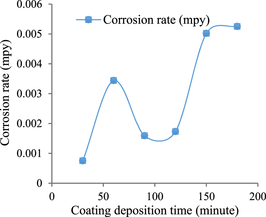
Effect of electroless Ni-P coating deposition time on corrosion rate (Ashassi-Sorkhabi and Rafizadeh 2004).
2.7.2 Temperature
Temperature is an important parameter which affects the rate of deposition of electroless Ni-P coating. The reactions occur during the deposition process are endothermic. As a consequence, the deposition rate increases by increasing the temperature. The impact of bath temperatures (Taheri 2002) on the deposition rate of the coating has been shown in Figure 9. Corrosion resistance increases with enhanced bath temperature at certain limit. The bulk of the acidic and salty baths are maintained at 80–90 °C while the alkaline baths can be run at lower temperature (40 °C).

Effect of bath temperature of the coating solution on the coating deposition rate (Taheri 2002).
2.7.3 pH
Many of the reactions involved in the deposition process of electroless Ni-P coating are susceptible to changes in solution pH. By increasing the pH of the coating bath solution, the phosphorus release from the hypophosphite is retarded whereas nickel-reduction reaction is accelerated. Equation (7) is the simplified form of Equations (5) and (6), corresponds to nickel reduction while Equation (8) corresponds to phosphorus reduction. From Equation (7), it can be concluded that the higher the concentration of H+ in the electroless bath is, the less the deposition of the Ni will be. At lower pH, the percentage of Ni content in the coating is low and the phosphorus content remains high. As the pH increases, Equation (7) is shifted to the right direction, causing a decrease in the concentration of H+, i.e., an increase in the Ni content in the coating. On the contrary, as the pH of the electroless bath decreases, the concentration of the OH− ions decrease and, consequently, the percentage of the P in the coating increases, which has been shown in Figure 10. Therefore, decreasing the pH of the solution increases the phosphorus content of the coating resulting in higher corrosion resistance.

Effect of coating solution pH on phosphorus content (Fayyad et al. 2019).
2.7.4 Coating thickness
The coating thickness is one of the parameters which is responsible for the porosity of the coating surface. As the thickness of the coating increases, the pores and tiny holes on coating surface diminishes, leading to enhanced corrosion resistance. Thicker coatings passivate at the lower corrosion current density and thus possess greater resistance to corrosion. The coating thickness of electroless Ni-P coated substrate was reported to be influenced by phosphorus content (Shibli and Dilimon 2007). This refers to the reduction of the coating’s porosity due to increased coating thickness. There is a close relation between the thickness of the coating and its corrosion resistance, as shown in Table 9.
Electroless Ni-P deposits at various thicknesses.
| Coating thickness (µm) | Corrosion current density, icorr (mA/cm2) | Corrosion potential, Ecorr (mV vs. SHE) | Phosphorus content (wt. %) | References |
|---|---|---|---|---|
| 0 | 61 × 10–3 | −298 | – | Taheri (2002) |
| 3 | 30 × 10–3 | −184 | – | Taheri (2002) |
| 9.57 | 3.6 × 10⁻³ | −183 | 10 | Shibli and Dilimon (2007) |
| 10.11 | 3.2 × 10⁻³ | −330 | 13 | Shibli and Dilimon (2007) |
| 11.02 | 0.82 × 10⁻³ | −270 | 18 | Shibli and Dilimon (2007) |
Summary of the coating parameters of electroless Ni-P coated substrates in NaCl solution have been shown in Table 10. As mentioned in the previous sections, there are various coating process parameters of electroless Ni-P based coatings which can highly influence the properties of corrosion resistance. Figure 11 demonstrates the range of these parameters that can effectively improve corrosion resistance of electroless Ni-P coating.
Summary of the coating parameters of electroless Ni-P coated substrates in NaCl solution.
| Substrate | Coating solution | Elemental composition | Coating operational parameters | Results | References | |||||
|---|---|---|---|---|---|---|---|---|---|---|
| NiSO4 (gm/L) | NaH2PO2 (gm/L) | Ni (wt.%) | P (wt.%) | Time (min) | Temperature (°C) | pH | icorr (mA/cm2) | Ecorr (mV vs. SHE) | ||
| Mild steel | 30 | 25 | 73.71 | 13.1 | 30 | 88 | 4.5 | 0.06 × 10⁻³ | −137 | Ashassi-Sorkhabi and Rafizadeh (2004) |
| 30 | 25 | 78.50 | 12.7 | 60 | 88 | 4.5 | 0.148 × 10⁻³ | −57 | Ashassi-Sorkhabi and Rafizadeh (2004) | |
| 30 | 25 | 79.40 | 12.2 | 90 | 88 | 4.5 | 0.129 × 10⁻³ | −101 | Ashassi-Sorkhabi and Rafizadeh (2004) | |
| 30 | 25 | 80.43 | 11.7 | 120 | 88 | 4.5 | 0.140 × 10⁻³ | −53 | Ashassi-Sorkhabi and Rafizadeh (2004) | |
| 30 | 25 | 83.13 | 10.8 | 150 | 88 | 4.5 | 0.278 × 10⁻³ | −216 | Ashassi-Sorkhabi and Rafizadeh (2004) | |
| 30 | 25 | 86.34 | 10.1 | 180 | 88 | 4.5 | 0.425 × 10⁻³ | −312 | Ashassi-Sorkhabi and Rafizadeh (2004) | |
| 21 | 24 | 91 | 9 | 60 | 90 | 4.5 | 3.62 × 10⁻³ | −113 | Narayanan et al. (2003) | |
| 30 | 25 | 88.10 | 8.30 | 60 | 85 | 4.5 | 0.98 × 10⁻³ | −189 | Shibli and Chinchu (2016) | |
| 21 | 24 | 90.1 | 9.9 | 60 | 90 | 4.8 | 0.640 × 10⁻³ | −126 | Balaraju et al. (2006b) | |
| 21.2 | 24 | 86.70 | 13.30 | 120 | 90 | 4.5 | 0.60 × 10⁻³ | −170 | Sankara Narayanan et al. (2006) | |
| 21.2 | 12 | 93.30 | 6.70 | 120 | 90 | 4.5 | 1.17 × 10⁻³ | −193 | Sankara Narayanan et al. (2006) | |
| 50 | 10 | 96.66 | 3.34 | 120 | 65 | 10 | 4.22 × 10⁻³ | −295 | Sankara Narayanan et al. (2006) | |
| 20 | 14.84 | 88.64 | 11.36 | 120 | 88 | 8 | 0.456 × 10⁻³ | −143 | Balaraju et al. (2006a) | |
| Copper | 52.6 | 42.4 | 80.51 | 7.12 | 30 | 85 | 5.0 | 8.02 × 10⁻³ | − | Shashikala and Sridhar (2020) |
| 25 | 20 | 90 | 8 | 60 | 90 | 9 | 0.285 × 10⁻³ | 16 | Gawad et al. (2013) | |
| Steel | 39.50 | 20 | 92.20 | 6.70 | 45 | 80 | 6.5 | 5.4 × 10⁻³ | −151 | Promphet et al. (2017) |
| 25 | 30 | 92.88 | 7.12 | 60 | 70 | 8 | 3.41 × 10⁻³ | −215 | Sharifalhoseini et al. (2018) | |
| Aluminium | 27 | 30 | 90.42 | 7.85 | 50 | 91 | 5 | 5.11 × 10⁻³ | −299 | Yin and Chen (2013) |
| 5083 Al alloy | 30 | 20 | 85.67 | 14.3 | 60 | 86 | 4 | 6.36 × 10⁻³ | −597 | Lee (2012) |
| 1050 Al alloy | 28 | 20 | 93.5 | 6.5 | 120 | 85 | 4.7 | 1.0 × 10⁻³ | −250 | Khollari et al. (2019) |
| 211Z Al alloy | 25 | 30 | 93.94 | 6.56 | 120 | 90 | 6 | 1.33 × 10⁻³ | −509 | Wu et al. (2015) |
| AZ31 Mg alloy | 20 | 22 | 90.29 | 9.71 | 60 | 75 | 7 | 1.7 × 10⁻³ | −188 | Ghavidel et al. (2020) |
| Carbon steel | 30 | 40 | 92.40 | 7.60 | 60 | 88 | 5.5 | 5.26 × 10⁻³ | −185 | Tamilarasan et al. (2017) |
| 15 | 25 | 89.09 | 8.85 | 60 | 85 | 5 | 7.14 × 10⁻³ | −160 | Luo et al. (2018) | |
| 25 | 30 | 93.20 | 6.30 | 120 | 85 | 5.5 | 4.0 × 10⁻³ | −178 | Luo et al. (2015) | |
| 23 | 21 | 89 | 11 | 120 | 88 | 4.9 | 1.66 × 10⁻³ | −79 | Balaraju et al. (2001) | |
| 15 | 30 | 89.09 | 10.91 | 180 | 85 | 8 | 4.50 × 10⁻³ | −323 | Fayyad et al. (2019) | |
| 21 | 24 | 62.2 | 37.8 | 180 | 90 | 4.5 | 3.83 × 10⁻³ | −228 | Momenzadeh and Sanjabi (2012) | |
| 21 | 24 | 84.3 | 15.7 | 180 | 94 | 4.5 | 6.81 × 10⁻³ | −296 | Novakovic and Vassiliou (2009) | |
| Brass | 30 | 25 | 92.50 | 7.5 | 240 | 90 | 5 | 2.21 × 10⁻³ | −220 | Gholizadeh-Gheshlaghi et al. (2018) |
| Polyester fabric | 17.5 | 25 | 90.1 | 9.02 | 60 | 73 | 8 | 0.11 × 10⁻³ | −58 | Jiang and Guo (2011) |
| Polymer carbon | 20 | 30 | 86 | 11.5 | 120 | 80 | 6.1 | 2.8 × 10⁻³ | −299 | Su et al. (2015) |

Factors influencing the corrosion resistance for electroless Ni-P based coatings.
3 Latest developed electrochemical techniques
3.1 Localized electrochemical impedance spectroscopy
The most recent development of electrochemical impedance spectroscopy (LEIS) is instigated by Lillard et al. (1992) which is further termed as localized electrochemical impedance spectroscopy (LEIS). The coated samples which have poor electrochemical activity can be measured by the LEIS system. An external voltage like previously mentioned in EIS method is applied to the LEIS system. A movable LEIS probe can measure the local potential difference. The schematic diagram for LEIS measurement has been shown in Figure 12. The electronic devices used in the LEIS setup are a gamry potentiostat which is integrated with a frequency response analyzer (FRA), two differential amplifiers, a LEIS probe and a computer monitor to visualize the data. Global and local impedances are recorded concurrently with a four-channel frequency response analyzer. Furthermore, transfer functions are generally analyzed by frequency response analyzer. A dual microprobe system has been introduced in this setup which is encompassed in the movable LEIS probe. The space between the two microprobes (micro reference electrodes) is denoted by ‘d’. The most modern LEIS instruments have a tolerance of around 1 nanovolt (nV). Differential amplifiers are used to monitor the data of local potential and current density by applying high input impedance. The two microprobes can sense the local potential difference from where current density can be calculated. The LEIS probe can travel in a three-dimensional motion and it is controlled by imposing digital signal. With providing information of position, velocity and direction, an encoder can regulate the positioning system of the LEIS probe (Cui et al. 2015; Huang et al. 2011). To enhance the ratio of signal and noise, the amplitude of sinusoidal voltage should be set as large as possible by performing the regulation of potentiostat. Some LEIS experiments have been conducted by using 50 acquisition cycles, seven points frequency per decade and 100 mV peak signal (Huang et al. 2007).
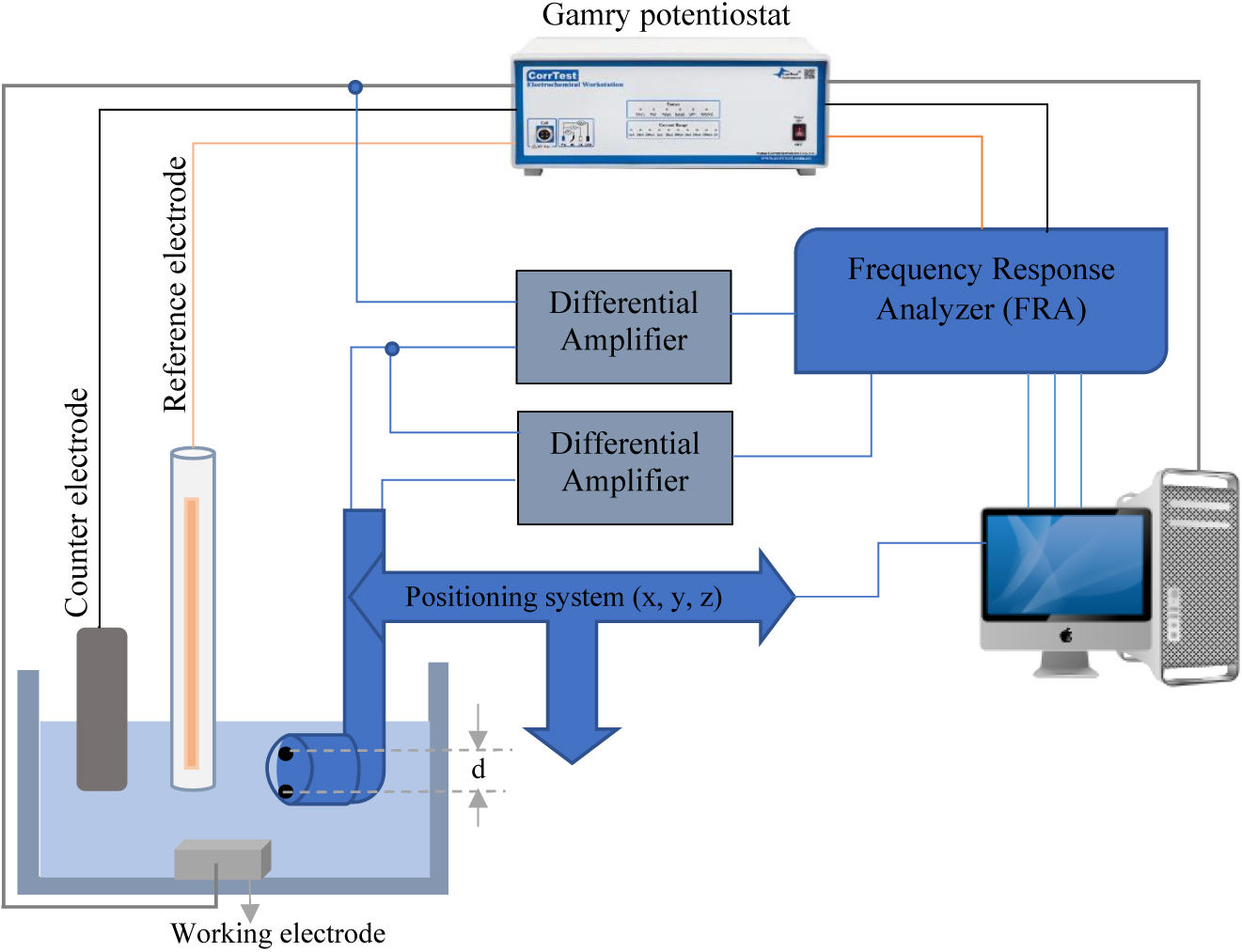
A schematic diagram of LEIS setup.
The dual microprobe (microelectrodes) consists of metallic wires. Each microprobe has its own metallic wires and they are connected with the individual differential amplifier. The diameter of those metallic wires can be measured in micrometers which are very tiny in nature. Molten glasses are used to seal the wires having very thin internal diameter, and the sealing process is carried out by a nichrome wire with a current controllable resistance heater (Jaffe and Nuccitelli 1974). However, in the case of Ag/AgCl microelectrodes, epoxy resin is used instead of molten glass for sealing the silver wires. A thin layer of silver chloride is formed according to the following electrochemical reaction by anodizing the silver microelectrode in KCl solution:
It is necessary to first clean the silver microelectrode in 2 M KCl solution at the condition of 241.20 VSHE at the rate of 100 mV/s. After passing 5–10 min, potentiodynamic oxidation occurs in that electrolyte with possessing 241.40 VSHE (Huang et al. 2011). The electrochemical tests are usually conducted at room temperature using a standard three-electrode cell. The dimension variation of Ag wires can make difference the potential value. The potential difference can be obtained by a platinum grid (counter electrode) with respect to a reference electrode as shown in the schematic diagram (Figure 12). There is a major impact of the microprobe size and its position on of LEIS measurement. A small microprobe is always desirable for the experiment. The resistance of electrolyte must be reduced in order to decrease the contribution of high frequencies, in accordance with experimental results for different probe positions above the working electrode (substrate).
The local current density can be measured by the closest microprobe through controlling ohmic drop. The LEIS measurement can therefore be improved using local interfacial impedance to avoid high frequency. A recent study has indicated that the consequences of the probe size (Abreu et al. 2017). Some authors have also suggested using the micro capillary electrochemical setup to solve the probe dimension difficulty (Pilaski et al. 2002).
3.2 Scanning vibrating electrochemical technique
Scanning vibrating electrochemical technique (SVET) setup employs a conductive vibrating probe that determines the potential difference between the probe and the substrate in an electrolyte. The vibrating probe is mounted on a piezoelectric actuator (Figure 13). A measurement probe can be positioned closely above the surface of the sample. The scanning probe instrument consists of a very thin platinum tip. This tip of SVET probe measures potential difference (ΔV). The SVET probe is typically positioned 150 µm apart from the current source point which normally supplies 60 nA current to the system. The probe is wrapped with an insulated thin platinum–iridium (Pt-Ir) wire. The tip is spherical in shape with 10 µm diameter and coated with black platinum. The probe is positioned 100 µm above from the surface and the frequency of vibration probe normally remains at 398 Hz (Gnedenkov et al. 2016). The piezoelectric motor can move in all three dimensions. The piezo ceramic device controls the movement of the probe allowing vibration amplitudes (d) from 1 to 60 µm in the direction perpendicular (Z axis) to the sample surface. An amount of 100 µA current (Bastos et al. 2017) flows between the graphite electrodes (B to C). This current is naturally generated from electrochemical corrosion or biological process and is externally controlled by a galvanostat. Potential difference is calculated from the circuit at selected points (A to D). The reference microelectrodes which contain low impedance are used to measure the ohmic drop in solution. Two reference microelectrodes are kept in a fixed position and they are moved together. Due to the developed compact electric field in the electrolyte solution, the potential difference exists. The current density (I) can be easily determined by measuring the potential difference (ΔV), the amplitude of vibration (d) and the solution resistivity (ρ) with the help of Equation (13). To get the value of current density, the method is repeated in a settled framework and acquires the data from the plot of current density over a selected sample surface (Dolgikh et al. 2016). From this current (I), corrosion rate can be measured.
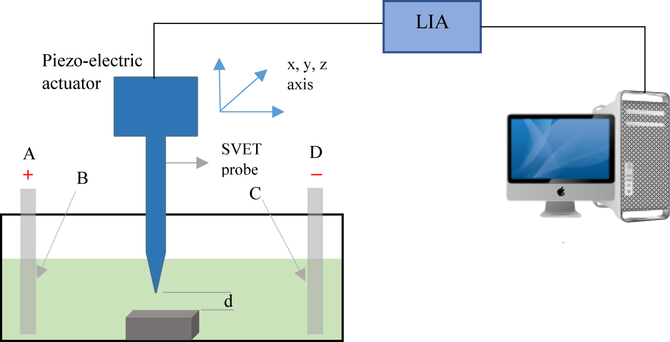
Schematic presentation of SVET.
The SVET probe position is regulated by an auto-generated computer command. The close loop linear encoders can identify the exact position of the probe. The vibrating nature of the probe in the perpendicular direction to the substrate surface can generate a zone where AC signal is developed. A lock-in amplifier (LIA) device is used to extract the AC signal with its carrier wave from an extremely noisy environment and converts it to a DC signal by using input phase angle. The LIA is able to capture and demodulate not just small AC signals but also large signals. The LIA acts as a rectifier in this SVET setup. The input phase angle is usually determined by manually changing the phase input of lock-in amplifier until no response is detected. The optimum phase angle can be gained by adding 90°. Some commercial equipment can be able to acquire the reference phase angle directly. The converted DC signal which is obtained from LIA device can then be plotted to represent the distribution of local activity. The SVET signal chain configuration has been shown in Figure 14.

SVET signal chain configuration.
The use of SVET in corrosion studies is subject to certain experimental drawbacks. The processing of data acquisition takes longer time in the matrix. Another difficulty can develop if the sample is not completely flat or is not placed properly accordance with the scanning probe (Jadhav and Gelling 2019). Larger amplitude vibrations may damage the substrate (McMurray et al. 2003) and inhibits the electrochemical corrosion reaction by rippling of the electrolytes resulting in an inaccurate value of current density. SVET methods can be applied to determine galvanic corrosion rate (Battocchi et al. 2005; Ogle et al. 2000; Simões et al. 2007), pitting corrosion (Dorman et al. 2017; Vuillemin et al. 2003; Williams et al. 2010), crevice corrosion (Isaacs 1996), stress corrosion cracking (Isaacs 1988), corrosion due to microorganisms (Abdul-Rani et al. 2019; Chen et al. 2015; Franklin et al. 1991; Iken et al. 2008), inorganic coatings (Manhabosco et al. 2015), coated materials (Ahmad et al. 2016; Bastos et al. 2010b), corrosion inhibitors (Bastos et al. 2010a; Kallip et al. 2012; Kumar et al. 2017; Toloei et al. 2013), corrosion of weldments (Bertoncello et al. 2015; Lollini et al. 2019) and corrosion of polymers (He et al. 2004).
3.3 Scanning ion-selective electrode technique
The scanning ion-selective electrode technique (SIET) works noninvasively and gives accurate measurements of the pH and the presence of specific ionic species just above surface of electrolyte (Fix et al. 2011). The schematic diagram of SIET setup has been shown in Figure 15A. The SIET probe contains a microelectrode (Figure 15B) consisting of a glass or plastic micropipette which is used for ion detection at the tip of the electrode along with pH variance detection (Cabrini et al. 2017). Ammann et al. (1985) had highlighted some technical studies on ion-selective microelectrodes. A selective ionophore-based membrane like oil is packed within a glass-capillary microelectrode. Between the ion-selective membrane and the metallic tip, an ion-to-electron transducer is mounted which is constructed from a conductive polymer poly (3-octylthiophene-2,5-diyl). The electrode’s ion-sensitive tip is approximately 10 μm long (Lamaka et al. 2010) and for various applications, this can range from 10 to 100 μm. A needle like Pt-Ir wire with an open tip is the base of the microelectrode. A competitive lateral resolution results from different diameter of the orifice of ion-selective glass-capillary microelectrode which ranges from 0.1 to 5 µm (Ammann et al. 1985).
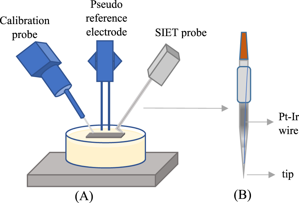
(A) Typical set up for SIET method (B) glass-capillary ion-selective microelectrode with liquid membrane.
Scanning ion-selective electrode technique functions as a micro-potentiometric instrument which works on an active solution surface to measure specific ions at a quasi-constant micro-distance. Potentiometric experiments are done under zero current circumstances in a two-electrode galvanic cell. A potentiometric cell is made up of a reference electrode and a microelectrode specific for ions. A SIET system includes the mentioned key elements: an ion-selective microelectrode positioned on a 3D computer-controlled stepper-motor system, which is used to place and transfer the microelectrode above the specimen. A video camera is located above the surface of the sample, fitted with a long-distance lens which provides magnification up to 400 times. It enhances and digitizes the potential difference evaluated inside this potentiometric cell. Ag/AgCl wires are used as a reference electrode. The micropipette including the reference electrode is placed on the computer-controlled 3D stepper motor. The sample is dissolved in the electrolyte and both electrodes are carried into the sample’s vicinity. Video-assisted camera optics captures the image data, help place the probe and hold the distance between sample and probe. Pre-assessment and post-assessment of SIET is extensively required for the microelectrode calibration. The travelling with motion and speed of the micropipette across the surface of the sample can be controlled by a computer-generated command. A 3D data represents the spread of pH or ionic concentration of sample. SIET tests are carried out in the context of potentiometry. Throughout this control mode the potential differences leading to variation in ionic concentration are evaluated. On the basis of its ability to allow the specific ions through the membrane, ionophore membranes are used in ion selective electrode. The chemical potential changes due to the diffusion of the ions through the membrane and thus potential variations are observed by means of the internal and external reference electrodes.
Usually, a silver chlorinated wire which is immersed into the electrolytes is used as a reference electrode. For SIET experiments, selective microelectrodes are generally placed 50 μm above from the tracked surface. According to the Nernst equation, calibration of H+-selective microelectrode is performed using the buffer solution. An ASET-2 (Science Wares) programming software can scan the respective area. The potential can be calculated by using 1 PΩ rated input impedance preamplifier (Gnedenkov et al. 2016). The ion selective electrodes have some drawbacks due to its physical structure. The micropipettes of glass are delicate and therefore fragile. During the analysis and in the calibration procedure, the transparent nature of glass makes it difficult to obtain the correct distance between the probe and the sample.
3.4 Scanning droplet cell technique
A scanning droplet cell (SDC) is a traditional three electrode experiment with a localized electrochemical cell scanned across the surface of the sample. A positive displacement pump is used in the SDC technique which can force the electrolyte from a gas-purged reservoir through a small diameter tube. The narrow tube generates a convection profile which can be controlled through pump rate. The electrolyte is then sprinkled into the single droplet on the surface of the substrate which acts as a working electrode. The cohesive forces between liquid molecules grasp this droplet on the surface and later can be dragged across the sample by dint of capillary action. As electrochemical reaction takes place between electrolyte and electrode, contact portion of the sample with droplet is measured. SDC experiments can be configured in one of the two ways. Firstly, by applying a constant bias such as potential or current and increment the position of the droplet creating a data map. Secondly, by applying a static or dynamic electrochemical signal to perform experiments such as Tafel or EIS as the droplet is held in a fixed position. Because the droplet is a self-contained, three electrode chemical cell. The force sensor which is mounted on a fixed position of the scanning flow cell (SFC) can measure the force of the droplet when pressed against the working electrode. The SFC consists of inlet and outlet channels which are intersected in a polycarbonate block and it also has an elliptical opening at the bottom of the cell body (Figure 16). The reference and the counter electrode are positioned directly into the channels of the SFC cell and the working electrode is located directly under the elliptical opening into an automatic three-dimensional stage. Ag/AgCl is used as reference electrode while platinum wire is used as counter electrode. To avoid the leakage of the electrolyte, a 150 µm (Schuppert et al. 2012) thick silicon gasket is attached at the opening of the electrode. The working electrode is 500 µm (Kulyk et al. 2015) far from the bottom of the cell. The droplet contact area and the capillary size should be as small as possible (Kollender et al. 2015; Snowden et al. 2010). Since the sample measurement area is very small, the induced current range is as little as in picoamperes. The high resolution potentiostat can measure this small amount of current. A constant polarization is applied during the time of scanning the SDC head and the droplet across the surface in one direction and then the responses (current, voltage and open circuit potential) are measured. Although the droplet motion on the surface is a dynamic process, the ohmic drop should be considered as well. Moreover, as it is a flow-type cell, it makes fast combination with downstream analysis or even with spectrometry. The SDC technique is suitable for both DC and AC measurements with the same configuration one after the other (Cherevko et al. 2014; Efaw et al. 2019).

3D diagram of scanning droplet cell.
3.5 Scanning electrochemical microscopy
Scanning electrochemical microscopy (SECM) methods can analyse the electric potential of working electrode (substrate) with higher accuracy. Using this technique, it can easily access to scan the surface reactions in macroscopic scale. The experimental setup (Figure 17) of SECM consolidates a piezo-electric actuator, a biopotentiostat and an ultra-microelectrode (UME) which is used as a SECM probe. The SECM probes are made of a noble metal and they are normally rigid. Ultra-microelectrod tip is vertically positioned above the surface of the substrate and can capture the topographic view of the surface of the substrate. Substrate and UME tip is regarded as working electrodes whereas platinum electrode can be used as a reference electrode. DC voltage is generally applied to the SECM probe to measure the current response. The bipotentiostat polarizes the UME tip as well as the substrate individually and it can measure the currents. Potentiostat is used to amplify the probe signal which is later converted to a digital signal. One electrode is responsible for conducting electrochemical reactions between the electrolytes and the substrate whereas the other one can measure the response. By changing the polarization level, tip collection and tip generation data can be monitored. A stepper motor gets response through the signal of position controller by a computer-generated program. The positioning system can scan the location of the measuring tip and through generating a data map; it can calculate the electrochemical parameters. The electric signal is then transmitted to the mechanical energy and piezo-electric actuator can drive the UME probe. The two-dimensional (X and Y) movements of the probe are controlled by a position controller but the vertical movement of the SECM probe is conducted manually with respect to the substrate surface. Current is recorded according to SECM probe position and is scanned in either X or Y direction. The sensitivity of the SECM is 100 µV (Beheshti et al. 2016, 2020).
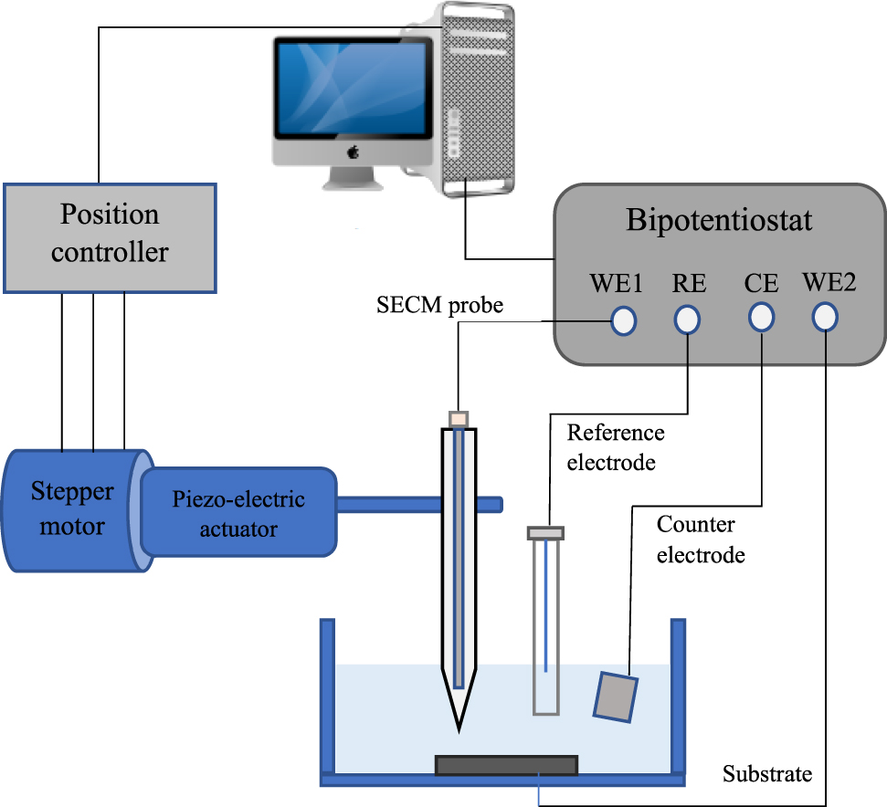
Schematic diagram of SECM experimental setup.
3.6 Scanning Kelvin probe
Scanning Kelvin probe (SKP) is a nondestructive method which does not require any conducting path between the kelvin probe and the substrate. Kelvin probe can measure work function difference in different media like vacuum, humid air, open air or using a drop of electrolyte on the surface by a non-destructive capacitance method (Wicinski et al. 2016). The metallic probe is generally made from tungsten which is enclosed by brass container. The vibration frequency and the maximum extent of vibration of the probe can be regulated in terms of their required speed and predefined height. The probe vibration produces current that is quashed by external potential. The specific configuration of the SKP setup can measure the capacitive height at the time of collecting data which in turn allows the Kelvin probe to falter the specific profile. Two parallel capacitors plate are used to measure the capacitive height. Between two parallel plates, one plate is regarded as the Kelvin probe surface and another plate is considered as the surface of the substrate. When the needle of the Kelvin probe is near the substrate then the energy variances of the electrons are observed. The energy that is required to remove an electron from the surface of the conductor forms the concept of work function and this work function difference varies the potential of conductive materials. The flow of electron can shift from the higher work function to the lower work function depending on the conductors’ properties. The relative work function can be associated with the value of corrosion potential (Ecorr). When two conductive surfaces come into electrical contact, the potential difference is induced. Thus, positive and negative charges are developed by the two different metals.
The respective potentials are denoted by EF1 and EF2 while
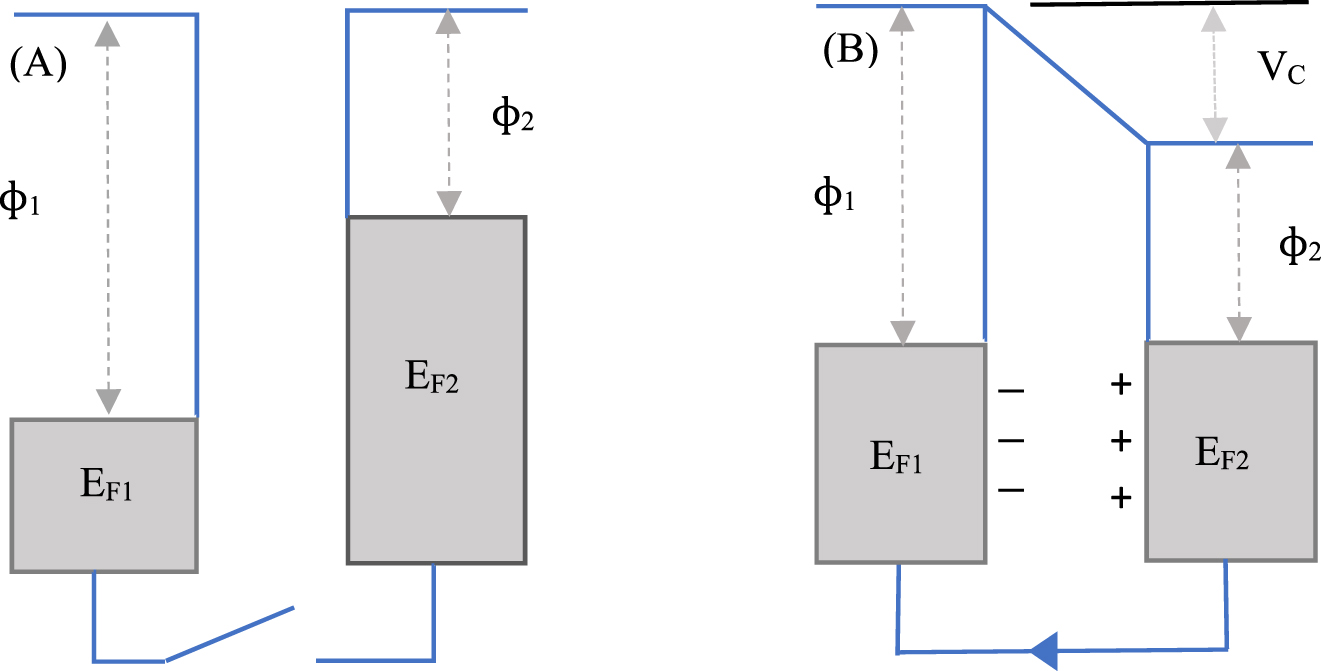
Energy and charge levels of the plates when they are (A) not electrically connected, (B) electrically connected.
An equal and opposite backing potential (VB) is applied in the plates to neutralize the potential difference (VC) during the vibration of the probe. To obtain the value of work function difference, the neutralize condition is essential during the measurements. This Volta potential can be termed as corrosion potential and determined by using following Equation (12).
where
The height regulating scanning Kelvin probe (HR-SKP) system was introduced to obtain the potential difference for the rough, curved, and irregular surfaces. The experimental setup of HR-SKP has been shown in Figure 19. This type of Kelvin probe consists of different electromechanical parts including a stepper motor, piezo electric actuator, speaker, isolator and a needle. The Kelvin probe is normally instructed by an acoustic signal ranging 1–2 kHz frequency (Wapner et al. 2005). The sample chamber can be positioned by a computer-generated command to fix the position between the needle and the substrate surface. A thin wire made by nickel/chromium is used as needle. The appropriate positioning of the needle is controlled by three stepper motors which can provide three dimensional directions. For height regulation, fast and accurate movements piezo-electric actuator is used which can move in Z direction and set the position vertically from the substrate surface. A function generator generates sinusoidal current at a frequency of 10 Hz keeping 300 mV voltage for the distance control circuit. Two computer screens are used to visualize the performance of the two control circuits which are internally connected to each other. At the very beginning of the experiment, X and Y directed stepper motors are driven by computer command to locate the corresponding point of the substrate surface. The piezoelectric actuator is moved by a height regulating circuit. If precise height is needed and the height is not adjusted with the actuator, then additional Z-stepper motor can be used combinedly with piezoelectric actuator to adjust the height. Only the needle distance is set manually while other all commands are performed automatically with computer-generated program. A LIA is applied for the potential measurement. After positioning the probe in a correct point upon the substrate surface, the Volta potential is measured by the potential control circuit. The LIA then commands the probe and the needle is moved to a next position.

Experimental setup of the HR-SKP.
This work function can be correlated to the corrosion or open circuit potential of bare or coated metals. One example of the application of the SKP is the study of the surface of a material beneath a coating to detect active corrosion sites or identify the potential for future corrosion site development. This technique has been additionally applied to the field of forensic, solar cell research and the development of organic light emitting diodes. Based on the principle of a capacitor, SKP allows the user to set and maintain the probe-to-sample distance enabling the researcher to negate topographical contribution across real world surface. In addition to being a non-destructive technique (NDT), SKP also allows for electrochemical analysis in the absence of electrolytes preserving the sample for future analysis. The SKP non-contacting optical surface profile (OSP) is an option which generates relative height information that can be used as the basis for constant distance mode operation. The OSP technique can also be used to map topographic changes on a sample surface to characterize corrosion pit size, number and depth.
3.7 Novel contactless technique
A modern measurement technique has recently been established that does not require direct physical contact between potentiostat and the substrate to calculate the polarization resistance (Rp). The system here developed is called the contactless technique for corrosion system. Normally, it is essential to establish a direct contact among all the electrodes to measure the polarization resistance and potential difference using suitable wires in order to polarize the substrate which acts as a working electrode. When a current flow between the electrolyte and the substrate, then it gets polarized and generates electrostatic separation. The effect can be accomplished either by putting the substrate in a magnetic field, or by using direct current (DC) or alternating current (AC). The approach is based on the observation that the electrode can be polarized by positioning it under the action of an external electrical field produced by the application of a current between two externals (A and C) graphite electrodes. By applying an external voltage or current to the substrate (M), the applied current can flow in parallel field lines across the electrolyte and electrostatically polarizes the substrate and thus measuring the response. The reference electrodes (REFA and REFC) can record the differences in potential. Figure 20 demonstrates the schematic representation of four-electrode system experimental setup, where all four electrodes are connected with a galvanostat. The system comprises substrate ‘M’ as the working electrode and tank is filled with the electrolyte. The most notable feature in this novel technique is that the substrate (M) is not connected electrically with the galvanostat and it is positioned vertically which is parallel to the reference and counter electrodes. Current is applied with a galvanostat/potentiostat by two graphite electrodes (A and C) to measure the response. Two saturated calomel reference electrodes (REFA and REFC) located adjacent to the bar are used to measure the voltage variation at both sides of the substrate (M) before and after the applied current. During corrosion process, the concentration of electrolyte may decrease due to the formation of soluble corrosive products.
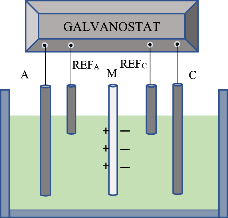
Schematic representation of electrode arrangements for novel contactless technique.
The measurement procedure of corrosion rate for this novel contactless method is performed by employing several steps. The equation Re = VRe/Iap is used to calculate the electrolyte resistance. An external current (Iap) (Andrade et al. 2008) is applied to the immersed substrate (M) in the electrolyte without touching it. This applied current polarizes the substrate by changing the potential through generating external electric field in the surrounding electrolyte. VRe is measured at the absence of the substrate (M) in the electrolyte with the four-electrode arrangement. After that the substrate (M) is immersed into the electrolyte and Ve+M is measured utilizing the same arrangement. The voltage differences between the reference electrodes (REFA and REFC) is regarded as the value of Ve+M where Ve+M = V2 − V0. Before testing, the voltage drop (V0) is measured between the reference electrodes and another voltage drop (V2) between the reference electrodes is counted after applying Iap current for a certain time usually taking less than 1 min to obtain the stable value of V2. The substrate resistance (RM) can be considered analogous to traditional polarization resistance (Rp). After several hours and days, Ve+M is then measured periodically to acquire RM values and to analyze whether it is equivalent to Rp or not. Figure 21 shows the electrical circuit for the contactless method where current flows parallelly through the substrate bar and the electrolyte. Two different paths are assumed for the current where one polarizes the substrate bar (M) and the other travels through the electrolyte. The following expression can determine the corrosion resistance of the substrate bar:
where, Re+M specifies the resistance when the substrate is present in the electrolyte, Re is the electrolyte resistance in the absence of the substrate and RM is the resistance of the substrate. Using the Stern–Geary relationship, the corrosion current (icorr) can be determined from RM (Stern and Geary 1957). The theoretical framework can be connected to the fact that the currents produced in the substrate are significantly proportional to the induced voltage due to the separation of charges, fulfilling the principle of the linear polarization method (Feliu et al. 1989). The ratio of the current and electric potential (induced voltage) is considered as the polarization resistance if the currents are directly proportional to the electric potential, which depends on the substrate condition. The feasibility of calculating the rate of corrosion without physical contact of the working electrode may unlock new horizon for smart applications and can be termed as non-destructive testing (NDT).

Electrical model used to represent the configuration of non-contact method.
Summary of the latest electrochemical corrosion measuring techniques has been shown in Table 11.
Summary of the latest electrochemical techniques.
| Method | Advantages | Disadvantages | Properties measured | Specifications | Applications |
|---|---|---|---|---|---|
| LEIS | Provides local impedance which cannot be obtained by any other method, good for insulated substrates, self-healing mechanism | Unintended inductance in circuit, slow measuring technique | Local capacitance, resistance | Sensitivity: 1 nV; polarization voltage: ±10 V; probe: Dual probe system | Inorganic/organic coating research, inhibitor studies, coating defects, interfacial impedance properties of coated metals |
| SVET | Real time mechanistic information, 2D-3D data presentation with image, simple experimental setup | Not suitable for irregular sample shape, and high amplitude of vibration, electrolyte may disappear, long duration measurement | Potential difference, current density | Sensitivity: 10 nV to 1 V; piezo vibration range: up to 30 µm; probe material: Pt/Ir | Bare metals corrosion, pits or crevices, biological systems |
| SIET | Can be combined with SVET, easy way to measure ion concentration | Fouling and damage to the ion selective electrode, Microcapillary tip is prone to breakage | Local pH, ion concentration | Piezo vibration range: up to 30 µm; probe material: Pt/Ir | Defects in coating or pits, kinetics of electrochemical process |
| SDC | Minimum electrolyte contact with surface, can do all the electro-chemistry technique with simple set up | Droplet drag, surface energy issues | Potential, current | Reference & counter electrode: Ag/AgCl & Pt wire; polarization voltage: ±10 V | Small area with large sample |
| SECM | Several modes of operation, can be combined with other techniques | Sometimes needs a redox active mediator, needs a bipotentiostat | Current, potential difference | Sensitivity: 100 µV; piezo vibration range: (10–25) µm; polarization voltage: ±10 V | Biological sensors, reaction kinetics, porous membrane study |
| SKP | No need of an electrolyte, short experiments, with the help of capacitive height measurement roughned surface can be measured, contactless method | Low resolution of SKP, need of probe calibration | Work function, potential difference, current | Sensitivity: 10 nV to 1 V; piezo vibration range: up to 30 µm; probe material: Tungsten | Measure corrosion under thin layers, rough or irregular surface, forensic research |
| NCT | It can provide visual inspection, empirical analysis, physical and electrochemical testing | Concentration of electrolyte may decrease | Current, metal resistance (RM) | Four electrodes are used | Reinforce steel |
4 Conclusions
This review article outlines the overall aspects on corrosion resistance for electroless Ni-P based composite coatings. It can be prognosticated that progressive modifications by varying different coating bath compositions and process parameters may provide new benefits and properties for Ni-P based composite coatings. The different concentration of soluble salt, complexing agent and buffer solution does not create any noticeable impact on corrosion properties of electroless Ni-P based composite coatings whereas reducing agent (sodium hypophosphite) has a significant influence on corrosion resistance. In Ni-P electroless coatings, phosphorus content between 9 and 18 wt% shows the best result in terms of corrosion resistance. However, heat treatment up to 300 °C for electroless Ni-P composite coated substrate has a detrimental effect on corrosion properties. The striking feature of the incorporation of nanoparticles (such as TiO2, SiC) to the electroless Ni-P plating bath solution is that it provides remarkable protection against corrosion. The effect of coating deposition time, bath solution temperature, pH of the coating solution of electroless Ni-P coatings has a slight impact on corrosion resistance. It is expected that the review presented of the effect of different factors on the aqueous corrosion behaviour of electroless Ni-P composite coatings will be helpful to the researchers working on the corrosive materials and their consistent development.
Moreover, a succinct overview of recent developed electrochemical techniques is provided in this paper. Although these techniques provide useful information by showing a new horizon in the corrosion measurement process, the required training, the interpretation of the measurement complexity, the time required for calibration, and the sample setting may be challenging for a researcher. With further developments in both instrumentation and software, the great advancements in electrochemical techniques over the last few years will certainly continue.
About the authors

Imtiaz ahmed Shozib received his B.Sc. degree in Mechanical Engineering in 2017 from Rajshahi University of Engineering and Technology (RUET), Bangladesh. He is currently a M.Sc. student at Universiti Teknologi PETRONAS, Malaysia. His research interests include biomaterials, antimicrobial activity on medical devices, corrosion properties, statistical optimization, and materials property prediction by machine learning. His area of expertise includes design of experiments, Minitab, High score plus, NOVA, programming language C. He has several journal publications to his credit.

Azlan Ahmad is currently a lecturer in Universiti Teknologi PETRONAS, Malaysia. He received his Ph.D. degree in Mechanical Engineering from Universiti Tun Hussein Onn Malaysia (UTHM), Malaysia. His research area includes manufacturing, aluminium recycling, metal forming, hot press forging, design of experiments. He has published in several high impact journals. He received a couple of awards during his academic life.

Ahmad Majdi Abdul-Rani is currently an associate professor at Universiti Teknologi PETRONAS, Malaysia. He received his Ph.D. degree from Loughborough University, UK. His area of expertise includes advanced manufacturing of biomedical implants; additive manufacturing of biomedical devices, reverse engineering, CAE/CAD/CAD/CAM/CNC, PDC bit design. He has published in more than 140 high impact journals and holds 4 patents. He received a lot of awards during his academic life.

Mohammadali Beheshti is a researcher at Universiti Teknologi Petronas, Malaysia. He holds a Bachelor’s degree in Materials Science and Engineering from Bu-Ali Sina University, Iran, and a Master’s degree in Materials Science and Engineering (Corrosion & Electrochemistry) from University of Tehran, Iran. He obtained his Ph.D. in Mechanical Engineering (Center for Corrosion Research) from Universiti Teknologi PETRONAS, Malaysia. His research interests include metallic and alloy coatings, corrosion, advanced materials, electrocatalysts and electrochemistry. He has published in several high-impact refereed journals and attended many conferences.

Abdul’Azeez Abdu Aliyu is a lecturer at Bayero University Kano, Nigeria. He completed his Master’s degree in Advanced Manufacturing Technology at Universiti Teknologi Malaysia. He obtained his Ph.D. in Mechanical Engineering from Universiti Teknologi PETRONAS, Malaysia. His research interests include advanced manufacturing of biomedical implants, additive manufacturing of biomedical devices, advanced materials, synthesis of bulk metallic glasses, CAD/CAM, advanced machining processes, modelling and simulation. He has published in several high impact journals and attended many conferences. He is currently a post-doctoral fellow at Chulalongkorn University of Bangkok, Thailand.
Acknowledgments
Imtiaz Ahmed Shozib would like to express his deep and sincere gratitude to his research supervisor, Dr. Azlan Ahmad, Lecturer, Universiti Teknologi PETRONAS, for providing him the valuable guidance throughout the writing of this review paper: Dr. Ahmad’s dynamism, vision, sincerity and motivation have deeply inspired him. Special thanks go to co-supervisor, Dr. Ahmad Majdi Abdul-Rani, Assoc. Prof., Universiti Teknologi PETRONAS for his valuable suggestions and evaluations, and to Dr. Mohammadali Beheshti and Dr. Abdul’Azeez Abdu Aliyu for their constant encouragement and genuine support throughout this work.
-
Author contributions: All the authors have accepted responsibility for the entire content of this submitted manuscript and approved submission.
-
Research funding: This research did not receive any specific grant from funding agencies in the public, commercial, or not-for-profit sectors.
-
Conflicts of interest: The authors declare no conflicts of interest regarding this article.
References
Abdel Aal, A. (2008). Hard and corrosion resistant nanocomposite coating for Al alloy. Mater. Sci. Eng. A 474: 181–187.10.1016/j.msea.2007.04.058Search in Google Scholar
Abdul-Rani, A.M., Rao, T., Axinte, E., Hastuty, S., Parameswari, R.P., Subramaniam, J.R., and Thyagarajan, S.P. (2019). Characterization, adhesion strength and in-vitro cytotoxicity investigation of hydroxyapatite coating synthesized on Zr-based BMG by electro discharge process. Surf. Coating. Technol. 370: 213–226.10.1016/j.surfcoat.2019.04.084Search in Google Scholar
de Abreu, C.P., de Assis, C.M., Suegama, P.H., Costa, I., Keddam, M., de Melo, H.G., and Vivier, V. (2017). Influence of probe size for local electrochemical impedance measurements. Electrochim. Acta 233: 256–261.10.1016/j.electacta.2017.03.017Search in Google Scholar
Ahmad, A., Lajis, M.A., Yusuf, N.K., and Wagiman, A. (2016). Hot press forging as the direct recycling technique of aluminium—a review. ARPN J. Eng. Appl. Sci 11: 2258–2265.Search in Google Scholar
Ahmadkhaniha, D., Eriksson, F., Leisner, P., and Zanella, C. (2018). Effect of SiC particle size and heat-treatment on microhardness and corrosion resistance of NiP electrodeposited coatings. J. Alloys Compd. 769: 1080–1087.10.1016/j.jallcom.2018.08.013Search in Google Scholar
Alaneme, K.K., Okotete, E.A., and Bodunrin, M.O. (2017). Microstructural analysis and corrosion behavior of Fe, B, and Fe-B-modified Cu-Zn-Al shape memory alloys. Corrosion Rev. 35: 3–11.10.1515/corrrev-2016-0053Search in Google Scholar
Allahkaram, S.R., Nazari, M.H., Mamaghani, S., and Zarebidaki, A. (2011). Characterization and corrosion behavior of electroless Ni–P/nano-SiC coating inside the CO2 containing media in the presence of acetic acid. Mater. Des. 32: 750–755.10.1016/j.matdes.2010.07.030Search in Google Scholar
Ameen, S., Shaheer Akhtar, M., and Shin, H.S. (2012). Growth and characterization of nanospikes decorated ZnO sheets and their solar cell application. Chem. Eng. J. 195–196: 307–313.10.1016/j.cej.2012.04.081Search in Google Scholar
Ammann, D., Pretsch, E., Simon, W., Lindner, E., Bezegh, A., and Pungor, E. (1985). Lipophilic salts as membrane additives and their influence on the properties of macro- and micro-electrodes based on neutral carriers. Anal. Chim. Acta 171: 119–129.10.1016/S0003-2670(00)84189-6Search in Google Scholar
Andrade, C. and Martínez, I. (2010). Techniques for measuring the corrosion rate (polarization resistance) and the corrosion potential of reinforced concrete structures. In: Non-destructive evaluation of reinforced concrete structures: non-destructive testing methods, pp. 284–316.10.1533/9781845699604.2.284Search in Google Scholar
Andrade, C., Martínez, I., and Castellote, M. (2008). Feasibility of determining corrosion rates by means of stray current-induced polarisation. J. Appl. Electrochem. 38: 1467–1476.10.1007/s10800-008-9591-6Search in Google Scholar
Ang, L.M., Hor, T.S.A., Xu, G.Q., Tung, C., Zhao, S., and Wang, J.L.S. (1999). Fabrication of nanostructures by hydroxylamine seeding of gold nanoparticle templates. Chem. Mater. 11: 2115–2118.10.1021/cm990078iSearch in Google Scholar
Aoki, K. and Takano, O. (1986). Corrosion characteristics of crystalline and amorphous electroless nickel-tungsten-phosphorus deposits. Plat. Surf. Finish. 73: 136–141.Search in Google Scholar
Araghi, A. and Paydar, M.H. (2010). Electroless deposition of Ni–P–B4C composite coating on AZ91D magnesium alloy and investigation on its wear and corrosion resistance. Mater. Des. 31: 3095–3099.10.1016/j.matdes.2009.12.042Search in Google Scholar
Ashassi-Sorkhabi, H. and Rafizadeh, S.H. (2004). Effect of coating time and heat treatment on structures and corrosion characteristics of electroless Ni–P alloy deposits. Surf. Coating. Technol. 176: 318–326.10.1016/S0257-8972(03)00746-1Search in Google Scholar
Assaf, F.H., Abou-Krisha, M.M., Daoush, W.M., and Eissa, A.A. (2018). Fabrication of Zn-Ni-Mn alloy by electrodeposition and its characterization. Corrosion Rev. 36: 547–558.10.1515/corrrev-2018-0003Search in Google Scholar
Baghery, P., Farzam, M., Mousavi, A.B., and Hosseini, M. (2010). Ni–TiO2 nanocomposite coating with high resistance to corrosion and wear. Surf. Coating. Technol. 204: 3804–3810.10.1016/j.surfcoat.2010.04.061Search in Google Scholar
Bahgat Radwan, A., Abdullah, A.M., and Alnuaimi, N.A. (2018). Recent advances in corrosion resistant superhydrophobic coatings. Corrosion Rev. 36: 127–153.10.1515/corrrev-2017-0012Search in Google Scholar
Bai, A., Chuang, P.-Y., and Hu, C.-C. (2003). The corrosion behavior of Ni–P deposits with high phosphorous contents in brine media. Mater. Chem. Phys. 82: 93–100.10.1016/S0254-0584(03)00193-7Search in Google Scholar
Balaraju, J.N., Selvi, V.E., Grips, V.K.W., and Rajam, K.S. (2006a). Electrochemical studies on electroless ternary and quaternary Ni–P based alloys. Electrochim. Acta 52: 1064–1074.10.1016/j.electacta.2006.07.001Search in Google Scholar
Balaraju, J.N., Kalavati, and Rajam, K.S. (2006b). Influence of particle size on the microstructure, hardness and corrosion resistance of electroless Ni–P–Al2O3 composite coatings. Surf. Coating. Technol. 200: 3933–3941.10.1016/j.surfcoat.2005.03.007Search in Google Scholar
Balaraju, J.N. and Rajam, K.S. (2005). Electroless deposition of Ni–Cu–P, Ni–W–P and Ni–W–Cu–P alloys. Surf. Coating. Technol. 195: 154–161.10.1016/j.surfcoat.2004.07.068Search in Google Scholar
Balaraju, J., Sankara Narayanan, T., and Seshadri, S. (2001). Evaluation of the corrosion resistance of electroless Ni-P and Ni-P composite coatings by electrochemical impedance spectroscopy. J. Solid State Electrochem. 5: 334–338.10.1007/s100080000159Search in Google Scholar
Bastidas, D.M., Valdez, B., Schorr, M., and Bastidas, J.M. (2019). Corrosion of copper intrauterine devices: review and recent developments. Corrosion Rev. 37: 307–320.10.1515/corrrev-2019-0012Search in Google Scholar
Bastos, A.C., Karavai, O.V., Zheludkevich, M.L., Yasakau, K.A., and Ferreira, M.G.S. (2010a). Localised measurements of pH and dissolved oxygen as complements to SVET in the investigation of corrosion at defects in coated aluminum alloy. Electroanalysis 22: 2009–2016.10.1002/elan.201000076Search in Google Scholar
Bastos, A.C., Zheludkevich, M.L., Klüppel, I., Grundmeier, G., and Ferreira, M.G.S. (2010b). Modification of zinc powder to improve the corrosion resistance of weldable primers. Prog. Org. Coating 69: 184–192.10.1016/j.porgcoat.2010.04.021Search in Google Scholar
Bastos, A.C., Quevedo, M.C., Karavai, O.V., and Ferreira, M.G.S. (2017). Review—on the application of the scanning vibrating electrode technique (SVET) to corrosion research. J. Electrochem. Soc. 164: C973–C990.10.1149/2.0431714jesSearch in Google Scholar
Battocchi, D., He, J., Bierwagen, G.P., and Tallman, D.E. (2005). Emulation and study of the corrosion behavior of Al alloy 2024-T3 using a wire beam electrode (WBE) in conjunction with scanning vibrating electrode technique (SVET). Corrosion Sci. 47: 1165–1176.10.1016/j.corsci.2004.06.021Search in Google Scholar
Beheshti, M., Kakooei, S., Ismail, M.C., and Shahrestani, S. (2016). Design and implementation of scanning electrochemical microscopy (SECM) for scanning open circuit potential system on damaged coated surfaces. J. Eng. Appl. Sci. 11: 14299–14302.Search in Google Scholar
Beheshti, M., Ismail, M.C., Kakooei, S., and Shahrestani, S. (2020). Influence of temperature and potential range on Zn-Ni deposition properties formed by cyclic voltammetry electrodeposition in chloride bath solution. Corrosion Rev. 38: 127–136.10.1515/corrrev-2019-0086Search in Google Scholar
Bertoncello, J.C.B., Manhabosco, S.M., and Dick, L.F.P. (2015). Corrosion study of the friction stir lap joint of AA7050-T76511 on AA2024-T3 using the scanning vibrating electrode technique. Corrosion Sci. 94: 359–367.10.1016/j.corsci.2015.02.029Search in Google Scholar
Bigdeli, F. and Allahkaram, S.R. (2009). An investigation on corrosion resistance of as-applied and heat treated Ni–P/nanoSiC coatings. Mater. Des. 30: 4450–4453.10.1016/j.matdes.2009.04.020Search in Google Scholar
Bonin, L., Vitry, V., and Delaunois, F. (2018). Corrosion behaviour of electroless high boron-mid phosphorous nickel duplex coatings in the as-plated and heat-treated states in NaCl, H2SO4, NaOH and Na2SO4 media. Mater. Chem. Phys. 208: 77–84.10.1016/j.matchemphys.2017.12.030Search in Google Scholar
Bubbico, R., Celata, G.P., D’Annibale, F., Mazzarotta, B., and Menale, C. (2015). Experimental analysis of corrosion and erosion phenomena on metal surfaces by nanofluids. Chem. Eng. Res. Des. 104: 605–614.10.1016/j.cherd.2015.10.004Search in Google Scholar
Cabrini, M., Lorenzi, S., Pastore, T., and Bolzoni, F.M. (2017). Environmentally assisted cracking of pipeline steels in CO2 containing environment at near-neutral pH. Corrosion Rev. 35: 309–323.10.1515/corrrev-2017-0053Search in Google Scholar
Calderón, J.A., Henao, J.E., and Gómez, M.A. (2014). Erosion–corrosion resistance of Ni composite coatings with embedded SiC nanoparticles. Electrochim. Acta 124: 190–198.10.1016/j.electacta.2013.08.185Search in Google Scholar
Chen, C.K., Feng, H.M., Lin, H.C., and Hon, M.H. (2002). The effect of heat treatment on the microstructure of electroless Ni–P coatings containing SiC particles. Thin Solid Films 416: 31–37.10.1016/S0040-6090(02)00628-4Search in Google Scholar
Chen, K., Dai, J., and Zhang, X. (2015). Improvement of corrosion resistance of magnesium alloys for biomedical applications. Corrosion Rev. 33: 101–117.10.1515/corrrev-2015-0007Search in Google Scholar
Cherevko, S., Zeradjanin, A.R., Topalov, A.A., Kulyk, N., Katsounaros, I., and Mayrhofer, K.J.J. (2014). Dissolution of noble metals during oxygen evolution in acidic media. ChemCatChem 6: 2219–2223.10.1002/cctc.201402194Search in Google Scholar
Chiba, M., Yamada, C., Okuyama, H., Sugiura, M., Pletincx, S., Verbruggen, H., Hyono, A., Graeve, I., Terryn, H., and Takahashi, H. (2018). Development of novel surface treatments for corrosion protection of aluminum: self-repairing coatings. Corrosion Rev. 36: 55–64.10.1515/corrrev-2017-0056Search in Google Scholar
Cissé, M., Abouchane, M., Anik, T., Himm, K., Belakhmima, R.A., Ebn Touhami, M., Touir, R., and Amiar, A. (2010). Corrosion resistance of electroless Ni-Cu-P ternary alloy coatings in acidic and neutral corrosive mediums. Int. J. Corros. 2010: 1–6.10.1155/2010/246908Search in Google Scholar
Clausmeyer, J., Masa, J., Ventosa, E., Öhl, D., and Schuhmann, W. (2016). Nanoelectrodes reveal the electrochemistry of single nickelhydroxide nanoparticles. Chem. Commun. 52: 2408–2411.10.1039/C5CC08796ASearch in Google Scholar
Court, S.W., Barker, B.D., and Walsh, F.C. (2000). Electrochemical measurements of electroless nickel coatings on zincated aluminium substrates. Trans. IMF 78: 157–162.10.1080/00202967.2000.11871330Search in Google Scholar
Cui, G., Li, N., Li, D., Zheng, J., and Wu, Q. (2006). The physical and electrochemical properties of electroless deposited nickel–phosphorus black coatings. Surf. Coating. Technol. 200: 6808–6814.10.1016/j.surfcoat.2005.10.015Search in Google Scholar
Cui, G., Li, Z., Yang, C., and Wei, X. (2015). Study on the interference corrosion of cathodic protection system. Corrosion Rev. 33: 233–247.10.1515/corrrev-2014-0061Search in Google Scholar
Ćurković, L., Ćurković, H.O., Salopek, S., Renjo, M.M., and Šegota, S. (2013). Enhancement of corrosion protection of AISI 304 stainless steel by nanostructured sol–gel TiO2 films. Corrosion Sci. 77: 176–184.10.1016/j.corsci.2013.07.045Search in Google Scholar
Das, C.M., Limaye, P.K., Grover, A.K., and Suri, A.K. (2007). Preparation and characterization of silicon nitride codeposited electroless nickel composite coatings. J. Alloys Compd. 436: 328–334.10.1016/j.jallcom.2006.07.036Search in Google Scholar
Delaunois, F. and Lienard, P. (2002). Heat treatments for electroless nickel–boron plating on aluminium alloys. Surf. Coating. Technol. 160: 239–248.10.1016/S0257-8972(02)00415-2Search in Google Scholar
Dhoke, S.K., Khanna, A.S., and Sinha, T.J.M. (2009). Effect of nano-ZnO particles on the corrosion behavior of alkyd-based waterborne coatings. Prog. Org. Coating 64: 371–382.10.1016/j.porgcoat.2008.07.023Search in Google Scholar
Diegle, R.B., Sorensen, N.R., Clayton, C.R., Helfand, M.A., and Yu, Y.C. (1988). An XPS investigation into the passivity of an amorphous Ni-20P alloy. J. Electrochem. Soc. 135: 1085–1092.10.1149/1.2095880Search in Google Scholar
Dolgikh, O., Demeter, A., Lamaka, S.V., Taryba, M., Bastos, A.C., Quevedo, M.C., and Deconinck, J. (2016). Simulation of the role of vibration on Scanning Vibrating Electrode Technique measurements close to a disc in plane. Electrochim. Acta 203: 379–387.10.1016/j.electacta.2016.01.188Search in Google Scholar
Dorman, S.E.G., Rausch, J.W., Arunachalam, S., and Fawaz, S.A. (2017). Examination and prediction of corrosion fatigue damage and inhibition. Corrosion Rev. 35: 355–363.10.1515/corrrev-2017-0057Search in Google Scholar
Du, Y., Zhang, X., Wei, L., Yu, B., Wang, Y., Wang, Y., and Ye, S. (2020). Electrodeposition of a Ni-P composite coating reinforced with Ti3C2Tx@TiO2/MoS2 particles. Mater. Chem. Phys. 241: 1–8.10.1016/j.matchemphys.2019.122448Search in Google Scholar
Efaw, C.M., da Silva, T., Davis, P.H., Li, L., Graugnard, E., and Hurley, M.F. (2019). Toward improving ambient volta potential measurements with SKPFM for corrosion studies. J. Electrochem. Soc. 166: 3018–3027.10.1149/2.0041911jesSearch in Google Scholar
Elansezhian, R., Ramamoorthy, B., and Nair, P.K. (2008). Effect of surfactants on the mechanical properties of electroless (Ni–P) coating. Surf. Coating. Technol. 203: 709–712.10.1016/j.surfcoat.2008.08.021Search in Google Scholar
Elsener, B., Crobu, M., Scorciapino, M.A., and Rossi, A. (2008). Electroless deposited Ni–P alloys: corrosion resistance mechanism. J. Appl. Electrochem. 38: 1053–1060.10.1007/s10800-008-9573-8Search in Google Scholar
Farag, A.A. (2020). Applications of nanomaterials in corrosion protection coatings and inhibitors. Corrosion Rev. 38: 67–86.10.1515/corrrev-2019-0011Search in Google Scholar
Fayyad, E.M., Abdullah, A.M., Hassan, M.K., Mohamed, A.M., Jarjoura, G., and Farhat, Z. (2018). Recent advances in electroless-plated Ni-P and its composites for erosion and corrosion applications: a review. Emerg. Mater. 1: 3–24.10.1007/s42247-018-0010-4Search in Google Scholar
Fayyad, E.M., Abdullah, A.M., Mohamed, A.M.A., Jarjoura, G., Farhat, Z., and Hassan, M.K. (2019). Effect of electroless bath composition on the mechanical, chemical, and electrochemical properties of new NiP–C3N4 nanocomposite coatings. Surf. Coating. Technol. 362: 239–251.10.1016/j.surfcoat.2019.01.087Search in Google Scholar
Feliu, S., González, J.A., Andrade, C., and Feliu, V. (1989). Polarization resistance measurements in large concrete specimens: mathematical solution for a unidirectional current distribution. Mater. Struct. 22: 199–205.10.1007/BF02472188Search in Google Scholar
Fix, D., Skorb, E.V., Shchukin, D.G., and Möhwald, H. (2011). Quantitative analysis of scanning electric current density and pH-value observations in corrosion studies. Meas. Sci. Technol. 22: 1–8.10.1088/0957-0233/22/7/075704Search in Google Scholar
Franklin, M.J., White, D.C., and Isaacs, H.S. (1991). Pitting corrosion by bacteria on carbon steel, determined by the scanning vibrating electrode technique. Corrosion Sci. 32: 945–952.10.1016/0010-938X(91)90014-GSearch in Google Scholar
Gawad, S.A., Baraka, A.M., Morsi, M.S., and Eltoum, M.S.A. (2013). Development of electroless Ni-P-Al2O3 and Ni-P-TiO2 composite coatings from alkaline hypophosphite gluconate baths and their properties. Int. J. Electrochem. Sci. 8: 1722–1734.10.1016/S1452-3981(23)14260-XSearch in Google Scholar
Georgieva, J. and Armyanov, S. (2007). Electroless deposition and some properties of Ni–Cu–P and Ni–Sn–P coatings. J. Solid State Electrochem. 11: 869–876.10.1007/s10008-007-0276-6Search in Google Scholar
Ghavidel, N., Allahkaram, S.R., Naderi, R., Barzegar, M., and Bakhshandeh, H. (2020). Corrosion and wear behavior of an electroless Ni-P/nano-SiC coating on AZ31 Mg alloy obtained through environmentally-friendly conversion coating. Surf. Coating. Technol. 382: 1–17.10.1016/j.surfcoat.2019.125156Search in Google Scholar
Gholizadeh-Gheshlaghi, M., Seifzadeh, D., Shoghi, P., and Habibi-Yangjeh, A. (2018). Electroless Ni-P/nano-WO3 coating and its mechanical and corrosion protection properties. J. Alloys Compd. 769: 149–160.10.1016/j.jallcom.2018.07.304Search in Google Scholar
Gnedenkov, A.S., Sinebryukhov, S.L., Mashtalyar, D.V., and Gnedenkov, S.V. (2016). Localized corrosion of the Mg alloys with inhibitor-containing coatings: SVET and SIET studies. Corrosion Sci. 102: 269–278.10.1016/j.corsci.2015.10.015Search in Google Scholar
Guo, Z., Keong, K.G., and Sha, W. (2003). Crystallisation and phase transformation behaviour of electroless nickel phosphorus platings during continuous heating. J. Alloys Compd. 358: 112–119.10.1016/S0925-8388(03)00069-0Search in Google Scholar
Hamada, A.S., Sahu, P., and Porter, D.A. (2015). Indentation property and corrosion resistance of electroless nickel–phosphorus coatings deposited on austenitic high-Mn TWIP steel. Appl. Surf. Sci. 356: 1–8.10.1016/j.apsusc.2015.07.153Search in Google Scholar
Hari Krishnan, K., Praveen, J., Ganesan, M., Kavimani, P.M., John, S., and Srinivasan, K.N. (2006). Electroless Ni-P-based composite coatings. Mater. Perform. 45: 36–39.10.5006/MP2006_45_8-36Search in Google Scholar
He, J., Tallman, D.E., and Bierwagen, G.P. (2004). Conjugated polymers for corrosion control: scanning vibrating electrode studies of polypyrrole-aluminum alloy interactions. J. Electrochem. Soc. 151: 644–651.10.1149/1.1819632Search in Google Scholar
Hu, C., Xu, M., Zhang, J., Hu, B., and Yu, G. (2019). High corrosion resistance of electroless Ni/Ni-B coating from fluoride-free baths on AZ31 magnesium alloy. J. Alloys Compd. 770: 48–57.10.1016/j.jallcom.2018.07.306Search in Google Scholar
Hu, X., Jiang, P., Wan, J., Xu, Y., and Sun, X. (2009a). Study of corrosion and friction reduction of electroless Ni–P coating with molybdenum disulfide nanoparticles. J. Coating Technol. Res. 6: 275–281.10.1007/s11998-008-9131-7Search in Google Scholar
Hu, X.G., Cai, W.J., Xu, Y.F., Wan, J.C., and Sun, X.J. (2009b). Electroless Ni–P–(nano-MoS2) composite coatings and their corrosion properties. Surf. Eng. 25: 361–366.10.1179/174329408X282532Search in Google Scholar
Hu, Y., Wang, T., Meng, J., and Rao, Q. (2006). Structure and phase transformation behaviour of electroless Ni–W–P on aluminium alloy. Surf. Coating. Technol. 201: 988–992.10.1016/j.surfcoat.2006.01.012Search in Google Scholar
Huang, V.M.-W., Vivier, V., Frateur, I., Orazem, M.E., and Tribollet, B. (2007). The global and local impedance response of a blocking disk electrode with local constant-phase-element behavior. J. Electrochem. Soc. 154: 89–98.10.1149/1.2398889Search in Google Scholar
Huang, V.M., Wu, S.-L., Orazem, M.E., Pébère, N., Tribollet, B., and Vivier, V. (2011). Local electrochemical impedance spectroscopy: a review and some recent developments. Electrochim. Acta 56: 8048–8057.10.1016/j.electacta.2011.03.018Search in Google Scholar
Huang, Y.S., Zeng, X.T., Hu, X.F., and Liu, F.M. (2004). Corrosion resistance properties of electroless nickel composite coatings. Electrochim. Acta 49: 4313–4319.10.1016/j.electacta.2004.04.023Search in Google Scholar
Huang, Z.H., Zhou, Y.J., and Nguyen, T.T. (2019). Study of nickel matrix composite coatings deposited from electroless plating bath loaded with TiB2, ZrB2 and TiC particles for improved wear and corrosion resistance. Surf. Coating. Technol. 364: 323–329.10.1016/j.surfcoat.2019.01.060Search in Google Scholar
Huang, Z. and Xiong, D. (2008). MoS2 coated with Al2O3 for Ni–MoS2/Al2O3 composite coatings by pulse electrodeposition. Surf. Coating. Technol. 202: 3208–3214.10.1016/j.surfcoat.2007.11.033Search in Google Scholar
Hughes, A.E., Parvizi, R., and Forsyth, M. (2015). Microstructure and corrosion of AA2024. Corrosion Rev. 33: 1–30.10.1515/corrrev-2014-0039Search in Google Scholar
Iken, H., Etcheverry, L., Bergel, A., and Basseguy, R. (2008). Local analysis of oxygen reduction catalysis by scanning vibrating electrode technique: a new approach to the study of biocorrosion. Electrochim. Acta 54: 60–65.10.1016/j.electacta.2008.02.120Search in Google Scholar
Isaacs, H.S. (1988). Initiation of stress corrosion cracking of sensitized type 304 stainless steel in dilute thiosulfate solution. J. Electrochem. Soc. 135: 2180–2183.10.1149/1.2096235Search in Google Scholar
Isaacs, H.S. (1996). Location of corrosion on iron and carbon steel surfaces with crevices. J. Electrochem. Soc. 143: 178–183.10.1149/1.1837022Search in Google Scholar
Jadhav, N. and Gelling, V.J. (2019). Review—the use of localized electrochemical techniques for corrosion studies. J. Electrochem. Soc. 166: 3461–3476.10.1149/2.0541911jesSearch in Google Scholar
Jaffe, L.F. and Nuccitelli, R. (1974). An ultrasensitive vibrating probe for measuring steady extracellular currents. J. Cell Biol. 63: 614–628.10.1083/jcb.63.2.614Search in Google Scholar PubMed PubMed Central
Jian, S.-Y., Chang, J.-K., Lin, K.-F., Chen, T.-Y., Yuan, J.-H., and Ger, M.-D. (2020). Characteristic V-Mn conversion coating in reinforcing corrosion resistance of electroless Ni-P coated LZ91 Mg alloy. Surf. Coating. Technol. 394: 1–13.10.1016/j.surfcoat.2020.125724Search in Google Scholar
Jiang, S.X. and Guo, R.H. (2011). Electromagnetic shielding and corrosion resistance of electroless Ni–P/Cu–Ni multilayer plated polyester fabric. Surf. Coating. Technol. 205: 4274–4279.10.1016/j.surfcoat.2011.03.033Search in Google Scholar
Jiang, W., Niu, Q., Cheng, L., Zhou, T., and Xie, H. (2020). Characterization of silicon acrylic resin containing silica nanoparticles as candidate materials for antifouling and anticorrosion properties in seawater. Corrosion Rev., https://doi.org/10.1515/corrrev-2019-0091 (Epub ahead of print).Search in Google Scholar
Jin, H.M., Jiang, S.H., and Zhang, L.N. (2008). Microstructure and corrosion behavior of electroless deposited Ni–P/CeO2 coating. Chin. Chem. Lett. 19: 1367–1370.10.1016/j.cclet.2008.06.040Search in Google Scholar
Kallip, S., Bastos, A.C., Yasakau, K.A., Zheludkevich, M.L., and Ferreira, M.G.S. (2012). Synergistic corrosion inhibition on galvanically coupled metallic materials. Electrochem. Commun. 20: 101–104.10.1016/j.elecom.2012.04.007Search in Google Scholar
Kathavate, V.S., Bagal, N.S., and Deshpande, P.P. (2019). Corrosion protection performance of nano-TiO2-containing phosphate coatings obtained by anodic electrochemical treatment. Corrosion Rev. 37: 565–578.10.1515/corrrev-2018-0094Search in Google Scholar
Keong, K.G., Sha, W., and Malinov, S. (2003). Computer modelling of the non-isothermal crystallization kinetics of electroless nickel–phosphorus deposits. J. Non-Cryst. Solids 324: 230–241.10.1016/S0022-3093(03)00246-1Search in Google Scholar
Kerr, C., Barker, D., and Walsh, F. (1997). Porosity and corrosion rate measurements for electroless nickel deposits on steel using electrochemical techniques. Trans. IMF 75: 81–87.10.1080/00202967.1997.11871148Search in Google Scholar
Kerr, C., Barker, D., and Walsh, F.C. (1996). Studies of porosity in electroless nickel deposits on ferrous substrates. Trans. IMF 74: 214–220.10.1080/00202967.1996.11871129Search in Google Scholar
Khollari, M.A.R., Ghorbani, M., and Afshar, A. (2019). Fabrication and characterization of TiO2 deposited black electroless Ni-P solar absorber. Appl. Surf. Sci. 496: 1–9.10.1016/j.apsusc.2019.143632Search in Google Scholar
Khorasani, S.A.H. and Sanjabi, S. (2016). High corrosion resistance Ni-reduced graphene oxide nanocomposite coating. Corrosion Rev. 34: 305–312.10.1515/corrrev-2016-0039Search in Google Scholar
Klomjit, P. and Buchheit, R.G. (2020). Cooperative and synergistic corrosion inhibition of AA 7075-T6 by praseodymium and CaSO4. Corrosion Rev. 38: 365–380.10.1515/corrrev-2020-0032Search in Google Scholar
Kollender, J.P., Voith, M., Schneiderbauer, S., Mardare, A.I., and Hassel, A.W. (2015). Highly customisable scanning droplet cell microscopes using 3D-printing. J. Electroanal. Chem. 740: 53–60.10.1016/j.jelechem.2014.12.043Search in Google Scholar
van der Kouwe, E.T. (1993). EIS as a means of evaluating electroless nickel deposits. Electrochim. Acta 38: 2093–2097.10.1016/0013-4686(93)80345-ZSearch in Google Scholar
Kubisztal, J., Kubisztal, M., Stach, S., and Haneczok, G. (2018). Corrosion resistance of anodic coatings studied by scanning microscopy and electrochemical methods. Surf. Coating. Technol. 350: 419–427.10.1016/j.surfcoat.2018.07.032Search in Google Scholar
Kulyk, N., Cherevko, S., Auinger, M., Laska, C., and Mayrhofer, K.J.J. (2015). Numerical simulation of an electrochemical flow cell with V-shape channel geometry. J. Electrochem. Soc. 162: 860–866.10.1149/2.0261512jesSearch in Google Scholar
Kumar, R., Chahal, S., Dahiya, S., Dahiya, N., Kumar, S., and Lata, S. (2017). Experimental and theoretical approach to exploit the corrosion inhibition activity of 3-formyl chromone derivatives on mild steel in 1 m H2SO4. Corrosion Rev. 35: 95–110.10.1515/corrrev-2017-0029Search in Google Scholar
Lamaka, S., Souto, R.M., and Ferreira, M.G.S. (2010). In-situ visualization of local corrosion by scanning ion-selective electrode technique (SIET). In: Méndez-Vilas, A. and Díaz, J., Microscopy: Science, technology, applications and education, Vol. 3, Formatex Research Center, Badajoz, Spain, pp. 2162–2173.Search in Google Scholar
Lee, C.-K. (2012). Comparative corrosion resistance of electroless Ni-P/nano-TiO2 and Ni-P/nano-CNT composite coatings on 5083 aluminum alloy. Int. J. Electrochem. Sci. 7: 12941–12954.10.1016/S1452-3981(23)16598-9Search in Google Scholar
Lee, S.-L. and Liang, H.-H. (1991). Structures and corrosion characteristics of electroless Ni-Mo-P alloy deposits. Plat. Surf. Finish. 78: 82–86.Search in Google Scholar
Li, X., Wang, Z., Qiu, Y., Pan, Q., and Hu, P. (2015). 3D graphene/ZnO nanorods composite networks as supercapacitor electrodes. J. Alloys Compd. 620: 31–37.10.1016/j.jallcom.2014.09.105Search in Google Scholar
Lillard, R.S., Moran, P.J., and Isaacs, H.S. (1992). A novel method for generating quantitative local electrochemical impedance spectroscopy. J. Electrochem. Soc. 139: 1007–1012.10.1149/1.2069332Search in Google Scholar
Liu, G., Yang, L., Wang, L., Wang, S., Chongyang, L., and Wang, J. (2010). Corrosion behavior of electroless deposited Ni–Cu–P coating in flue gas condensate. Surf. Coating. Technol. 204: 3382–3386.10.1016/j.surfcoat.2010.03.056Search in Google Scholar
Liu, Q., Zhou, Q., Venezuela, J., Zhang, M., Wang, J., and Atrens, A. (2016). A review of the influence of hydrogen on the mechanical properties of DP, TRIP, and TWIP advanced high-strength steels for auto construction. Corrosion Rev. 34: 127–152.10.1515/corrrev-2015-0083Search in Google Scholar
Liu, X., Tan, Y., Zhang, X., Liao, Q., and Wang, Z. (2020). Fabrication and performance evaluation of nickel-rich conductive coating for carbon steel grounding grids in saline-alkali soil solution. Corrosion Rev. 38: 263–271.10.1515/corrrev-2019-0112Search in Google Scholar
Liu, Y.Y., Yu, J., Huang, H., Xu, B.H., Liu, X.L., Gao, Y., and Dong, X.L. (2007). Synthesis and tribological behavior of electroless Ni–P–WC nanocomposite coatings. Surf. Coating. Technol. 201: 7246–7251.10.1016/j.surfcoat.2007.01.035Search in Google Scholar
Liu, Y. and Zhao, Q. (2004). Study of electroless Ni–Cu–P coatings and their anti-corrosion properties. Appl. Surf. Sci. 228: 57–62.10.1016/j.apsusc.2003.12.031Search in Google Scholar
Lo, P., Tsai, W., Lee, J., and Hung, M. (1995). The electrochemical behavior of electroless plated Ni‐P alloys in concentrated NaOH solution. J. Electrochem. Soc. 142: 91–96.10.1149/1.2043954Search in Google Scholar
Lollini, F., Carsana, M., Gastaldi, M., and Redaelli, E. (2019). Corrosion behaviour of stainless steel reinforcement in concrete. Corrosion Rev. 37: 3–19.10.1515/corrrev-2017-0088Search in Google Scholar
Lu, G. and Zangari, G. (2002). Corrosion resistance of ternary Ni-P based alloys in sulfuric acid solutions. Electrochim. Acta 47: 2969–2979.10.1016/S0013-4686(02)00198-6Search in Google Scholar
Luo, H., Leitch, M., Behnamian, Y., Ma, Y., Zeng, H., and Luo, J.-L. (2015). Development of electroless Ni–P/nano-WC composite coatings and investigation on its properties. Surf. Coating. Technol. 277: 99–106.10.1016/j.surfcoat.2015.07.011Search in Google Scholar
Luo, H., Leitch, M., Zeng, H., and Luo, J.-L. (2018). Characterization of microstructure and properties of electroless duplex Ni-WP/Ni-P nano-ZrO2 composite coating. Mater. Today Phys. 4: 36–42.10.1016/j.mtphys.2018.03.001Search in Google Scholar
Ma, C., Wu, F., Ning, Y., Xia, F., and Liu, Y. (2014). Effect of heat treatment on structures and corrosion characteristics of electroless Ni–P–SiC nanocomposite coatings. Ceram. Int. 40: 9279–9284.10.1016/j.ceramint.2014.01.150Search in Google Scholar
Mallory, G.O. and Hajdu, J.B. (1990). Electroless plating: fundamentals and applications. Cambridge University Press.Search in Google Scholar
Manhabosco, S.M., Batista, R.J.C., da Silva, S.N., and Dick, L.F.P. (2015). Determination of current maps by SVET of hot-dip galvanized steel under simultaneous straining. Electrochim. Acta 168: 89–96.10.1016/j.electacta.2015.03.162Search in Google Scholar
Marzocchi, V., Iglesias-Rubianes, L., Thompson, G.E., and Bellucci, F. (2007). The influence of tartaric acid additions on the anodizing behaviour of AA2024-T3 alloy in sulphuric acid. Corrosion Rev. 25: 461–474.10.1515/CORRREV.2007.25.3-4.461Search in Google Scholar
McMurray, H.N., Williams, D., and Worsley, D.A. (2003). Artifacts induced by large-amplitude probe vibrations in localized corrosion measured by SVET. J. Electrochem. Soc. 150: 567–578.10.1149/1.1623494Search in Google Scholar
Mimani, T. and Mayanna, S.M. (1996). The effect of microstructure on the corrosion behaviour of electroless Ni-P alloys in acidic media. Surf. Coating. Technol. 79: 246–251.10.1016/0257-8972(95)02446-8Search in Google Scholar
Momenzadeh, M. and Sanjabi, S. (2012). The effect of TiO2 nanoparticle codeposition on microstructure and corrosion resistance of electroless Ni-P coating. Mater. Corros. 63: 614–619.10.1002/maco.201005985Search in Google Scholar
Morales, A.G.R., Guzmán, M.O.C., and Arteaga, C.C. (2011). A brief review on fabrication and applications of auto-organized TiO2 nanotube arrays. Corrosion Rev. 29: 105–121.10.1515/corrrev.2011.500Search in Google Scholar
Narayanan, T.S.N.S., Krishnaveni, K., and Seshadri, S.K. (2003). Electroless Ni–P/Ni–B duplex coatings: preparation and evaluation of microhardness, wear and corrosion resistance. Mater. Chem. Phys. 82: 771–779.10.1016/S0254-0584(03)00390-0Search in Google Scholar
Narayanan, T.S.N.S. and Seshadri, S.K. (2009). Recent advances in surface treatment and electrodeposition. Corrosion Rev. 27: 533–600.10.1515/CORRREV.2009.27.S1.533Search in Google Scholar
Niaz, A. and Bakare, M.S. (2015). Electrochemical corrosion testing and characterization of potential assisted passive layer on HVOF Inconel 625 coating. Corrosion Rev. 33: 63–76.10.1515/corrrev-2014-0037Search in Google Scholar
Ningshen, S., Mudali, U.K., and Raj, B. (2009). Electrochemical impedance spectroscopy and its applications in corrosion research. Corrosion Rev. 27: 493–531.10.1515/CORRREV.2009.27.S1.493Search in Google Scholar
Novakovic, J., Vassiliou, P., Samara, K., and Argyropoulos, T. (2006). Electroless NiP–TiO2 composite coatings: their production and properties. Surf. Coating. Technol. 201: 895–901.10.1016/j.surfcoat.2006.01.005Search in Google Scholar
Novakovic, J. and Vassiliou, P. (2009). Vacuum thermal treated electroless NiP–TiO2 composite coatings. Electrochim. Acta 54: 2499–2503.10.1016/j.electacta.2008.12.015Search in Google Scholar
Ogle, K., Baudu, V., Garrigues, L., and Philippe, X. (2000). Localized electrochemical methods applied to cut edge corrosion. J. Electrochem. Soc. 147: 3654–3660.10.1149/1.1393954Search in Google Scholar
Okamoto, Y., Nitta, Y., Imanaka, T., and Teranishi, S. (1980). Surface state and catalytic activity and selectivity of nickel catalysts in hydrogenation reactions: III. Electronic and catalytic properties of nickel catalysts. J. Catal. 64: 397–404.10.1016/0021-9517(80)90512-6Search in Google Scholar
Pilaski, M., Hamelmann, T., Moehring, A., and Lohrengel, M.M. (2002). Impedance spectroscopy in micro systems. Electrochim. Acta 47: 2127–2134.10.1016/S0013-4686(02)00085-3Search in Google Scholar
Promphet, N., Rattanawaleedirojn, P., and Rodthongkum, N. (2017). Electroless NiP-TiO2 sol-RGO: a smart coating for enhanced corrosion resistance and conductivity of steel. Surf. Coating. Technol. 325: 604–610.10.1016/j.surfcoat.2017.07.018Search in Google Scholar
Rabizadeh, T. and Allahkaram, S.R. (2011). Corrosion resistance enhancement of Ni–P electroless coatings by incorporation of nano-SiO2 particles. Mater. Des. 32: 133–138.10.1016/j.matdes.2010.06.021Search in Google Scholar
Raicheff, R. and Zaprianova, V. (2000). Effect of crystallization on the electrochemical corrosion behavior of some nickel-based amorphous alloys. J. Mater. Sci. Lett. 19: 3–5.Search in Google Scholar
Ranganatha, S., Venkatesha, T.V., and Vathsala, K. (2010). Development of electroless Ni–Zn–P/nano-TiO2 composite coatings and their properties. Appl. Surf. Sci. 256: 7377–7383.10.1016/j.apsusc.2010.05.076Search in Google Scholar
Sahayaraj, M.E., Jappes, J.T.W., Siva, I., and Saravanan, M.S.S. (2014). A comparative corrosion study of electroless Ni-P coatings treated by microwave and conventional furnace annealing. Corrosion Rev. 32: 43–49.10.1515/corrrev-2013-0052Search in Google Scholar
Sahoo, P. and Das, S.K. (2011). Tribology of electroless nickel coatings – a review. Mater. Des. 32: 1760–1775.10.1016/j.matdes.2010.11.013Search in Google Scholar
Sankara Narayanan, T.S.N., Baskaran, I., Krishnaveni, K., and Parthiban, S. (2006). Deposition of electroless Ni–P graded coatings and evaluation of their corrosion resistance. Surf. Coating. Technol. 200: 3438–3445.10.1016/j.surfcoat.2004.10.014Search in Google Scholar
Schorr, M. and Valdez, B. (2016). The phosphoric acid industry: equipment, materials, and corrosion. Corrosion Rev. 34: 85–102.10.1515/corrrev-2015-0061Search in Google Scholar
Schuppert, A.K., Topalov, A.A., Katsounaros, I., Klemm, S.O., and Mayrhofer, K.J.J. (2012). A scanning flow cell system for fully automated screening of electrocatalyst materials. J. Electrochem. Soc. 159: 670–675.10.1149/2.009211jesSearch in Google Scholar
Sekhavat Pour, Z., Ghaemy, M., Bordbar, S., and Karimi-Maleh, H. (2018). Effects of surface treatment of TiO2 nanoparticles on the adhesion and anticorrosion properties of the epoxy coating on mild steel using electrochemical technique. Prog. Org. Coating 119: 99–108.10.1016/j.porgcoat.2018.02.019Search in Google Scholar
Sequeira, C.A.C., Cardoso, D.S.P., Amaral, L., Šljukić, B., and Santos, D.M.F. (2016). On the performance of commercially available corrosion-resistant nickel alloys: a review. Corrosion Rev. 34: 187–200.10.1515/corrrev-2016-0014Search in Google Scholar
Sharifalhoseini, Z. and Entezari, M.H. (2015). The new aspects of the anticorrosive ZnO@SiO2 core–shell NPs in stabilizing of the electrolytic Ni bath and the Ni coating structure; electrochemical behavior of the resulting nano-composite coatings. J. Colloid Interface Sci. 455: 110–116.10.1016/j.jcis.2015.05.047Search in Google Scholar PubMed
Sharifalhoseini, Z., Entezari, M.H., and Shahidi, M. (2018). Direct growth of ZnO nanostructures on the Zn electroplated mild steel to create the surface roughness and improve the corrosion protection of the electroless Ni-P coating. Mater. Sci. Eng., B 231: 18–27.10.1016/j.mseb.2018.07.001Search in Google Scholar
Shashikala, A.R. and Sridhar, B.S. (2020). Codeposition of electroless Ni-P/ZnO nano composites and evaluation of corrosion resistance of the coatings. Mater. Today: Proceedings, https://doi.org/10.1016/j.matpr.2020.05.447 (Epub ahead of print).Search in Google Scholar
Shibli, S.M.A. and Chinchu, K.S. (2016). Development and electrochemical characterization of Ni‐P coated tungsten incorporated electroless nickel coatings. Mater. Chem. Phys. 178: 21–30.10.1016/j.matchemphys.2016.04.034Search in Google Scholar
Shibli, S.M.A. and Dilimon, V.S. (2007). Effect of phosphorous content and TiO2-reinforcement on Ni–P electroless plates for hydrogen evolution reaction. Int. J. Hydrogen Energy 32: 1694–1700.10.1016/j.ijhydene.2006.11.037Search in Google Scholar
Shinato, K.W., Zewde, A.A., and Jin, Y. (2020). Corrosion protection of copper and copper alloys in different corrosive medium using environmentally friendly corrosion inhibitors. Corrosion Rev. 38: 101–109.10.1515/corrrev-2019-0105Search in Google Scholar
Shozib, I.A., Ahmad, A., Majdi, A., and Tasnim, N. (2020). Electroless Ni-P-TiO2 (ENPT) composite coating: a review on microstructural characteristics and multifarious properties for surgical instruments. Solid State Technol. 63: 3989–3996.Search in Google Scholar
Simões, A.M., Bastos, A.C., Ferreira, M.G., González-García, Y., González, S., and Souto, R.M. (2007). Use of SVET and SECM to study the galvanic corrosion of an iron–zinc cell. Corrosion Sci. 49: 726–739.10.1016/j.corsci.2006.04.021Search in Google Scholar
Snowden, M.E., King, P.H., Covington, J.A., Macpherson, J.V., and Unwin, P.R. (2010). Fabrication of versatile channel flow cells for quantitative electroanalysis using prototyping. Anal. Chem. 82: 3124–3131.10.1021/ac100345vSearch in Google Scholar PubMed
Song, L.Z., Song, S.Z., and Zhao, J. (2006). Preparation and corrosion resistance of NiP/TiO2 composite film on carbon steel in sulfuric acid solution. Acta Metall. Sin. 19: 117–123.10.1016/S1006-7191(06)60032-XSearch in Google Scholar
Sosa Domínguez, A., Pérez Bueno, J.J., Zamudio Torres, I., and Mendoza López, M.L. (2017). Characterization and corrosion resistance of electroless black Ni-P coatings of double black layer on carbon steel. Surf. Coating. Technol. 326: 192–199.10.1016/j.surfcoat.2017.07.044Search in Google Scholar
Srinivasan, K.N., Meenakshi, R., Santhi, A., Thangavelu, P.R., and John, S. (2010). Studies on development of electroless Ni–B bath for corrosion resistance and wear resistance applications. Surf. Eng. 26: 153–158.10.1179/174329409X409468Search in Google Scholar
Stern, M. and Geary, A.L. (1957). Electrochemical polarization: I. A theoretical analysis of the shape of polarization curves. J. Electrochem. Soc. 104: 56–63.10.1149/1.2428496Search in Google Scholar
Su, Y., Zhou, B., Liu, L., Lian, J., and Li, G. (2015). Electromagnetic shielding and corrosion resistance of electroless Ni‐P and Ni‐P‐Cu coatings on polymer/carbon fiber composites. Polym. Compos. 36: 923–930.10.1002/pc.23012Search in Google Scholar
Sudagar, J., Lian, J., and Sha, W. (2013). Electroless nickel, alloy, composite and nano coatings – a critical review. J. Alloys Compd. 571: 183–204.10.1016/j.jallcom.2013.03.107Search in Google Scholar
Sukkasi, S., Sahapatsombut, U., Sukjamsri, C., Saenapitak, S., and Boonyongmaneerat, Y. (2011). Electroless Ni-based coatings for biodiesel containers. J. Coating Technol. Res. 8: 141–147.10.1007/s11998-010-9286-xSearch in Google Scholar
Taheri, R. (2002). Evaluation of electroless nickel-phosphorus (EN) coatings, Ph.D. thesis. Saskatoon, University of Saskatchewan.Search in Google Scholar
Tamilarasan, T.R., Rajendran, R., Rajagopal, G., and Sudagar, J. (2015). Effect of surfactants on the coating properties and corrosion behaviour of Ni–P–nano-TiO2 coatings. Surf. Coating. Technol. 276: 320–326.10.1016/j.surfcoat.2015.07.008Search in Google Scholar
Tamilarasan, T.R., Sanjith, U., Shankar, M.S., and Rajagopal, G. (2017). Effect of reduced graphene oxide (rGO) on corrosion and erosion-corrosion behaviour of electroless Ni-P coatings. Wear 390: 385–391.10.1016/j.wear.2017.09.004Search in Google Scholar
Toloei, A., Atashin, S., and Pakshir, M. (2013). Corrosion rate of carbon steel under synergistic effect of seawater parameters including pH, temperature, and salinity in turbulent condition. Corrosion Rev. 31: 135–144.10.1515/corrrev-2013-0032Search in Google Scholar
Trueba, M. and Trasatti, S.P. (2015). Electrochemical approach to repassivation kinetics of Al alloys: gaining insight into environmentally assisted cracking. Corrosion Rev. 33: 373–393.10.1515/corrrev-2015-0054Search in Google Scholar
Uma Rani, R., Sharma, A.K., Minu, C., Poornima, G., and Tejaswi, S. (2010). Studies on black electroless nickel coatings on titanium alloys for spacecraft thermal control applications. J. Appl. Electrochem. 40: 333–339.10.1007/s10800-009-9980-5Search in Google Scholar
Uysal, M. (2019). Electroless codeposition of Ni-P composite coatings: effects of graphene and TiO2 on the morphology, corrosion, and tribological properties. Metall. Mater. Trans. 50: 2331–2341.10.1007/s11661-019-05161-9Search in Google Scholar
Vitry, V., Kanta, A.-F., Dille, J., and Delaunois, F. (2012a). Structural state of electroless nickel–boron deposits (5wt.% B): characterization by XRD and TEM. Surf. Coating. Technol. 206: 3444–3449.10.1016/j.surfcoat.2012.02.003Search in Google Scholar
Vitry, V., Sens, A., Kanta, A.-F., and Delaunois, F. (2012b). Wear and corrosion resistance of heat treated and as-plated Duplex NiP/NiB coatings on 2024 aluminum alloys. Surf. Coating. Technol. 206: 3421–3427.10.1016/j.surfcoat.2012.01.049Search in Google Scholar
Vitry, V., Delaunois, F., and Dumortier, C. (2008). Mechanical properties and scratch test resistance of nickel–boron coated aluminium alloy after heat treatments. Surf. Coating. Technol. 202: 3316–3324.10.1016/j.surfcoat.2007.12.001Search in Google Scholar
Vojtěch, D., Novák, M., Zelinková, M., Novák, P., Michalcová, A., and Fabián, T. (2009). Structural evolution of electroless Ni–P coating on Al–12wt.% Si alloy during heat treatment at high temperatures. Appl. Surf. Sci. 255: 3745–3751.10.1016/j.apsusc.2008.10.026Search in Google Scholar
Vuillemin, B., Philippe, X., Oltra, R., Vignal, V., Coudreuse, L., Dufour, L.C., and Finot, E. (2003). SVET, AFM and AES study of pitting corrosion initiated on MnS inclusions by microinjection. Corrosion Sci. 45: 1143–1159.10.1016/S0010-938X(02)00222-6Search in Google Scholar
Wang, H.-L., Liu, L.-Y., Dou, Y., Zhang, W.-Z., and Jiang, W.-F. (2013). Preparation and corrosion resistance of electroless Ni-P/SiC functionally gradient coatings on AZ91D magnesium alloy. Appl. Surf. Sci. 286: 319–327.10.1016/j.apsusc.2013.09.079Search in Google Scholar
Wang, L., Zhao, L., Zhang, B., Hu, W., Shu, X., Sheng, X., and Fang, Z. (1999). Crystallization study of electroless Fe–Sn–B amorphous alloy deposits. J. Alloys Compd. 287: 234–238.10.1016/S0925-8388(99)00064-XSearch in Google Scholar
Wapner, K., Schoenberger, B., Stratmann, M., and Grundmeier, G. (2005). Height-regulating scanning kelvin probe for simultaneous measurement of surface topology and electrode potentials at buried polymer/metal interfaces. J. Electrochem. Soc. 152: 114–122.10.1149/1.1856914Search in Google Scholar
Wicinski, M., Burgstaller, W., and Hassel, A.W. (2016). Lateral resolution in scanning Kelvin probe microscopy. Corrosion Sci. 104: 1–8.10.1016/j.corsci.2015.09.008Search in Google Scholar
Williams, G., Coleman, A.J., and McMurray, H.N. (2010). Inhibition of Aluminium Alloy AA2024-T3 pitting corrosion by copper complexing compounds. Electrochim. Acta 55: 5947–5958.10.1016/j.electacta.2010.05.049Search in Google Scholar
Wu, X., Mao, J., Zhang, Z., and Che, Y. (2015). Improving the properties of 211Z Al alloy by enhanced electroless Ni–P–TiO2 nanocomposite coatings with TiO2 sol. Surf. Coating. Technol. 270: 170–174.10.1016/j.surfcoat.2015.03.006Search in Google Scholar
Wu, Y., Gao, J., Shen, B., Liu, L., Hu, W., and Ding, W. (2005). Process and properties of electroless Ni-P-PTFE composite coatings. Plat. Surf. Finish. 92: 38–42.Search in Google Scholar
Xing, F., Zhao, B., and Shi, W. (2013). Study on tunable fabrication of the ultra-black Ni–P film and its blacking mechanism. Electrochim. Acta 100: 157–163.10.1016/j.electacta.2013.03.145Search in Google Scholar
Xu, X., Chen, D., Yi, Z., Jiang, M., Wang, L., Zhou, Z., Fan, X., Wang, Y., and Hui, D. (2013). Antimicrobial mechanism based on H2O2 generation at oxygen vacancies in ZnO crystals. Langmuir 29: 5573–5580.10.1021/la400378tSearch in Google Scholar PubMed
Xu, Y., Zhang, H., Li, X., Wang, W., and Li, J. (2017). Ag-encapsulated single-crystalline anatase TiO2 nanoparticle photoanodes for enhanced dye-sensitized solar cell performance. J. Alloys Compd. 695: 1104–1111.10.1016/j.jallcom.2016.10.236Search in Google Scholar
Yin, Z. and Chen, F. (2013). Effect of nickel immersion pretreatment on the corrosion performance of electroless deposited Ni–P alloys on aluminum. Surf. Coating. Technol. 228: 34–40.10.1016/j.surfcoat.2013.04.001Search in Google Scholar
Zanella, C., Lekka, M., Rossi, S., and Deflorian, F. (2011). Study of the influence of sonication during the electrodeposition of nickel matrix nanocomposite coatings on the protective properties. Corrosion Rev. 29: 253–260.10.1515/CORRREV.2011.005Search in Google Scholar
Zeller, R.L.III (1991). Electrochemical corrosion testing of high phosphorus electroless nickel in 5% NaCl. Corrosion 47: 692–702.10.5006/1.3585309Search in Google Scholar
Zhang, S., Han, K., and Cheng, L. (2008). The effect of SiC particles added in electroless Ni–P plating solution on the properties of composite coatings. Surf. Coating. Technol. 202: 2807–2812.10.1016/j.surfcoat.2007.10.015Search in Google Scholar
Zhao, G., Wang, R., Liu, S., Wu, D., Zhang, Y., Wang, T., and Zou, Y. (2020). Study on the role of element Mo in improving thermal stability and corrosion resistance of amorphous Ni-P deposit. J. Non-Cryst. Solids 549: 1–11.10.1016/j.jnoncrysol.2020.120358Search in Google Scholar
Zhao, Q., Liu, Y., and Abel, E.W. (2004). Effect of Cu content in electroless Ni–Cu–P–PTFE composite coatings on their anti-corrosion properties. Mater. Chem. Phys. 87: 332–335.10.1016/j.matchemphys.2004.05.028Search in Google Scholar
Zheng, C. and Yi, G. (2017). Investigating the influence of hydrogen on stress corrosion cracking of 2205 duplex stainless steel in sulfuric acid by electrochemical impedance spectroscopy. Corrosion Rev. 35: 23–33.10.1515/corrrev-2016-0060Search in Google Scholar
Zhou, P., Cai, W., Yang, Y., Li, X., Zhang, T., and Wang, F. (2019). Effect of ultrasonic agitation during the activation process on the microstructure and corrosion resistance of electroless Ni-W-P coatings on AZ91D magnesium alloy. Surf. Coating. Technol. 374: 103–115.10.1016/j.surfcoat.2019.05.080Search in Google Scholar
Zuleta, A.A., Galvis, O.A., Castaño, J.G., Echeverría, F., Bolivar, F.J., Hierro, M.P., and Pérez-Trujillo, F.J. (2009). Preparation and characterization of electroless Ni–P–Fe3O4 composite coatings and evaluation of its high temperature oxidation behaviour. Surf. Coating. Technol. 203: 3569–3578.10.1016/j.surfcoat.2009.05.025Search in Google Scholar
© 2021 Walter de Gruyter GmbH, Berlin/Boston
Articles in the same Issue
- Frontmatter
- Review
- A review on the corrosion resistance of electroless Ni-P based composite coatings and electrochemical corrosion testing methods
- Original Articles
- Water-droplet erosion behavior of high-velocity oxygen-fuel-sprayed coatings for steam turbine blades
- Corrosion characteristics of plasma spray, arc spray, high velocity oxygen fuel, and diamond jet coated 30MnB5 boron alloyed steel in 3.5 wt.% NaCl solution
- Corrosive-wear behavior of LSP/MAO treated magnesium alloys in physiological environment with three pH values
- Effect of carbon nanotubes on microstructure and corrosion resistance of PEO ceramic coating of magnesium alloy
- Investigating the efficacy of Curcuma longa against Desulfovibrio desulfuricans influenced corrosion in low-carbon steel
- Annual Reviewer Acknowledgement
- Reviewer acknowledgement Corrosion Reviews volume 39 (2021)