
Straight and helical plating with locking plates for proximal humeral shaft fractures – a biomechanical comparison under physiological load conditions
-
Christian Halbauer
 ,
Felix Capanni
,
Felix Capanni

Abstract
Objectives
Helical plating is an established method for treating proximal humeral shaft fractures, mitigating the risk of iatrogenic radial nerve damage. However, biomechanical test data on helical plates under physiological load condition is limited. Hence, the aim of this study was to compare the biomechanical performance of helical and straight PHILOS® Long plates in AO12C2 fractures using static and cyclic implant system testing.
Methods
Helical and straight PHILOS® Long plates on artificial bone substitutes were tested under physiological axial static (n=6) and cyclic loading (n=12). The axial construct stiffness was the main parameter for comparing the biomechanical performance of the two groups. Mimicking a clinical scenario, the helical deformation was performed consecutively by an experienced surgeon using iron bending tools. The torsional angle was determined computationally from 3D-scanning models afterwards.
Results
Helical plating resulted in a significantly reduced axial construct stiffness in all test scenarios compared to conventional straight plating (static testing: p=0.012; cyclic testing: p≤0.010). No failure occurred within the range of physiological loading in both groups.
Conclusions
Helical plating favors multidimensional deformation of the test sample in lateral-ventral direction under axial loading, resulting in a reduced axial construct stiffness and in an increased interfragmentary movement. No biomechanical failure is to be expected within physiological load boundaries.
Introduction
The approach of helical plating for treating humeral fractures was first introduced by Gill and Torchia [1] in the year 1999 as a new surgical technique to preserve the rotator cuff tendons and to prevent iatrogenic radial nerve damage during surgery. Helical plating is until today an established method of osteosynthesis for humeral fractures with growing popularity. Iatrogenic radial nerve damage, a potential risk of plate osteosynthesis for diaphyseal humerus fractures with complication rates from 2.7 to 20 % [2], [3], [4], [5], [6], [7], [8], can be prevented by using a helical shaped bone plate that bypasses the anatomical path of the radial nerve [3], [9], [10], [11], [12], [13]. Numerous clinical studies show the efficiency of that surgical technique with zero cases of iatrogenic radial nerve damage [11], [14], [15], [16], [17], [18]. Literature shows thereby the common use of the implant system PHILOS® Long by DePuy Synthes (Johnson & Johnson, USA), which is therefore bent manually to a helically shaped form using two iron bending tools. However, the torsional twist of the bone plate varies in literature between 45 and 90° and a specific range of torsion is not stated as recommendation [3], [8], [9], [10], [11], [12, 17], 19], 20].
Apart from the advantages of helical plating in surgery, the plastically deformed implant system needs to withstand postoperative, physiological loads to ensure adequate biomechanical stability of the fractured bone. Besides the popularity of helical plating with PHILOS® Long in surgery, helical deformation is not defined as an intended use within the instructions for use of the PHILOS® system, shifting the responsibility of safe use towards the clinics. However, only two previously published studies are available in literature that focus on the biomechanical investigation via implant system testing (IST) regarding the performance of helical deformed plates treating a comminuted humeral fracture (AO12C3) [19], 20]. In that context, additional investigations are necessary to understand the biomechanics of helical plating for various fracture types to be treated with, especially related to the PHILOS® Long system.
The aim of this study was to compare the biomechanical performance of helical plating vs. conventual straight plating via static and cyclic IST within physiological boundary conditions in case of a commonly treated AO12C2 fracture. It is hypothesized that the plastic deformation weakens the stability of the plate and therefore reduces the stiffness of the whole construct.
A previously published systematic literature review regarding biomechanical testing of osteosynthetic locking plates for proximal humeral shaft fractures builds the base for this study [21]. Biomechanical plausibility will be considered by analyzing the OrthoLoad® database to address physiological loading [22], 23].
Materials and methods
Test sample configuration and sample groups
Two sample groups were compared to one another via axial implant system testing (IST). Therefore, 18 test samples (n=18) were constructed of a fractured, artificial bone substitute and the implant system PHILOS® Long 10-holes by DePuy Synthes. The first test sample group, further referenced as ‘Philos-straight’, was assembled with the bone plate in its original straight state. The second test sample group, further referenced as ‘Philos-helical’, featured a helical deformed PHILOS® Long bone plate.
All artificial bones simulated an AO12C2 fracture with a 5 mm fracture gap at the proximal third and diaphyseal center according to the AO-Classification [24]. To ensure consistency of the fracture location, a custom saw jig was designed and 3D printed, which adapts to the anatomical form of the humerus in a single position only. For this purpose, a 3D model of the artificial bone was created using the Artec Eva-M 3D scanner (Artec Europe, Senningerberg, Luxembourg), as seen in Figure 1.
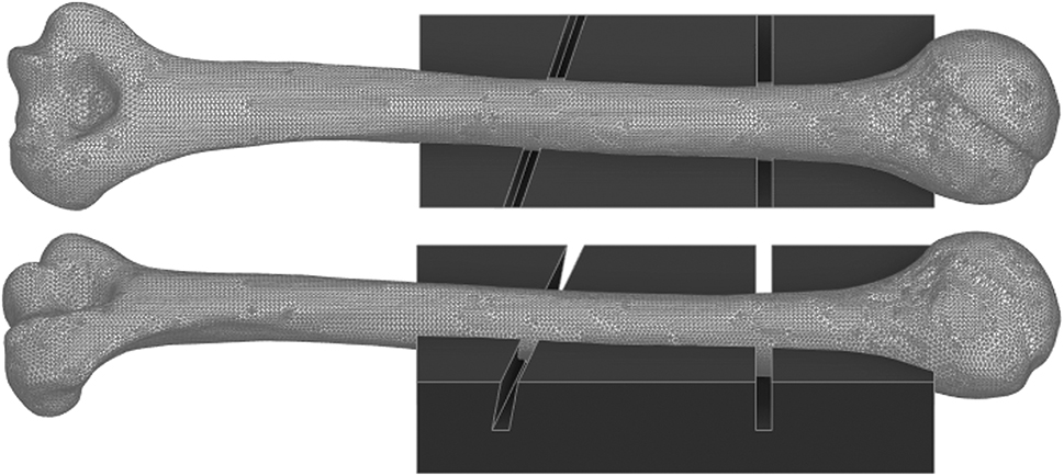
Computational 3D model of the Synbone® humerus type 5010 and a custom saw jig that adapts to the bone in a single position only, that acts as a cutting guide to perform a consistent osteotomy (AO12C2) for all samples.
The helical deformation of the plate was manually performed consecutively by an experienced surgeon for orthopedic and trauma surgery using two iron bending tools. To mimic a clinical scenario, the degree of torsion was not defined in terms of a specific angle of torsion and was therefore only based on surgical experience. The torsional angle was measured afterwards to check for potential variance and suboptimal replicability (see section ‘Determination of torsional angle’).
An identical screw configuration was used for both sample groups to fixate the implant lateral on the humerus according to AO recommendations. Before attaching the Ø3.5 mm screws, the artificial bone was pre-drilled at all screw positions using a drill sleeve and a 2.8 mm drill bit. The screws were then attached with a screwdriver with 1.5 Nm torque limiting attachment. A minimum screw length was chosen to lock the screws bi-cortical at the diaphyseal segment. The complete screw configuration is displayed in Figure 2.
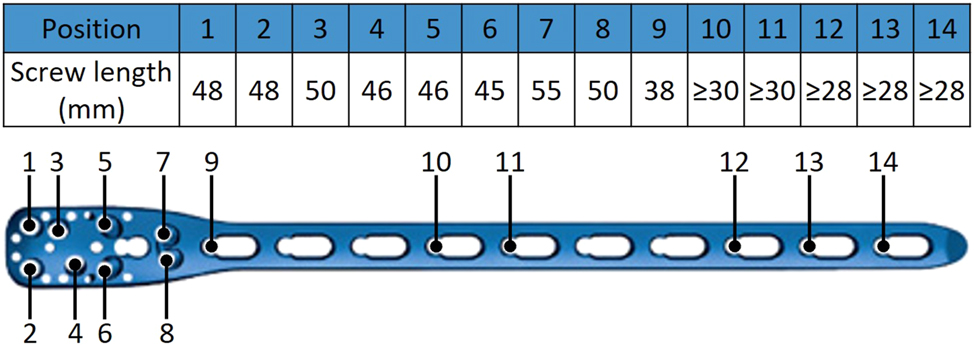
Screw configuration of the implant system PHILOS® long 10-holes used identically for both sample groups.
Literature reviews for humeral IST indicate the use of two brands for artificial bones for static and cyclic testing – Synbone® and Sawbones®. Becker et al. [25] however showed that Synbone® humerus models tend to fail early under torsional cyclic loading. It is to be expected, that early failure of the Synbone® humerus models might occur under axial cyclic loading too. The difference in axial construct stiffness for the presented IST is yet to be analyzed. Consequently, static test samples were constructed of a Synbone® humerus type 5010, whereas cyclic test samples were constructed of a Sawbones® humerus 3404. Therefore, the axial construct stiffness of the static tests can be compared to the initial loading of the cyclic load protocol (see section ‘Test setup and load protocols’).
Determination of torsional angle
The torsional angle of the helical samples was measured via 3D scanning to check the replicability of the manually performed deformation and the dimension of variance within the sample group. Therefore, two 3D printed adapters with a flat top surface were clipped into unused screw holes of the plate, one above and one below the section of torsional deformation. The flat surfaces of the adapters act thereby as reference planes. Next, each sample with attached adapters was 3D scanned and digitalized. Within the 3D modelling software Ansys® SpaceClaim® (ANSYS, Inc., Canonsburg, PA, USA), a reference plane was created for each adapter surface by selecting 10 triangular faces of the tessellated flat surface of each adapter. Finally, the torsional angle of the helical plate can be determined by measuring the dihedral angle ϕ between the two virtual planes in 3D space. The procedure to determine the torsional angle is visualized in Figure 3.
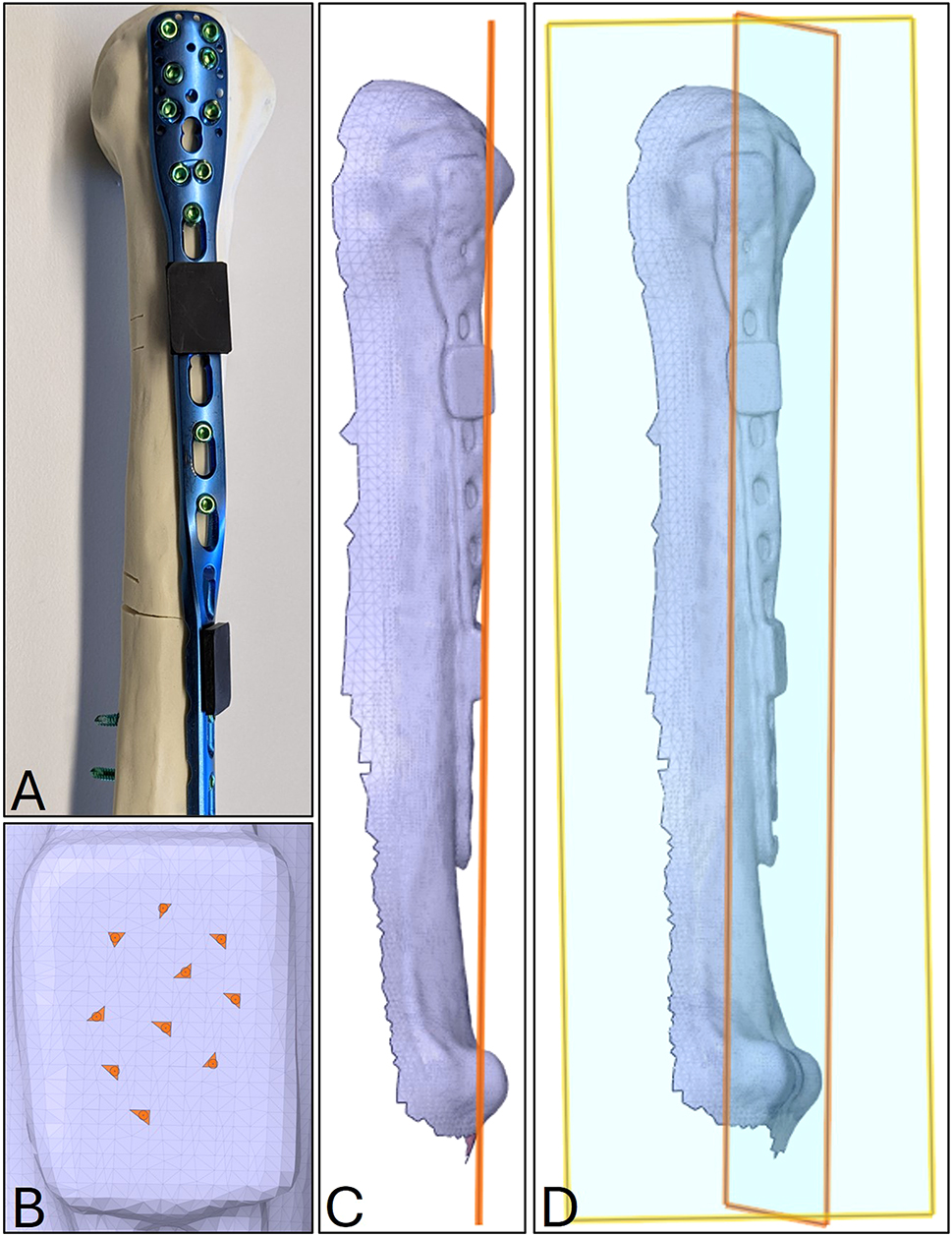
Procedure to determine the torsional angle of the helical plates via 3D scanning. (A) Helical test sample with two 3D printed adapters (black components) clipped into unused screw holes above and below the deformed section of the bone plate; (B) selection of 10 triangular faces of the tessellated flat surface of the lower adapter of the digitalized sample (C) virtual plane of the lower adapter based on the 10 triangular faces; (D) visualization of the two skew planes in 3D space, describing the torsion angle by their angle to one another.
Physiological loading and axial orientation
To evaluate the biomechanical performance of the two sample groups via testing, a physiological load limit based on post-operative loads during functional movements of the humerus is needed. An open-access source for such loads is the OrthoLoad® database, offering in-vivo data of an instrumented shoulder implant capable of measuring the resulting loads in the glenohumeral joint during arm movement.
As guidelines for post-operative care and rehabilitation recommend early mobilization in form of flexion and abduction of the arm to a limit of 90° [26], the OrthoLoad® database was analyzed regarding the maximum axial load component during that movements. In total, 27 datasets of in-vivo measurements of abduction and flexion of a straight arm raise without extra weight were analyzed (abduction n=19; flexion n=8). On average, the maximum axial load component corresponds to approximately 60 % of the patient’s body weight. To determine a physiological load limit for testing, a reference patient of 80 kg body weight was chosen, resulting in a maximum axial load component of 471 N.
At the OrthoLoad® database, the available loads and moments in x-, y- and z-direction are based on a recommendation of the International Society of Biomechanics (ISB) on joint coordinate systems by Wu et al. [27]. In that context, the artificial bone substitute needs to be aligned to the same coordinate system in the test setup to apply the load correctly. Therefore, the available scan model of each bone substitute was loaded in Ansys® SpaceClaim® and orientated manually to match the global coordinate system to ISB recommendation.
The z-axis aligns with a reference line between two anatomical landmarks (medial and lateral epicondyle) that define the rotational axis of the elbow joint. The y-axis crosses the highest point of the humeral head and is perpendicular to the elbow joint axis. The triangular plane described by the lateral and medial epicondyle and the highest point of the humeral head represents the frontal plane, as seen in Figure 4. Sagittal and transversal plane result in perpendicular relation.
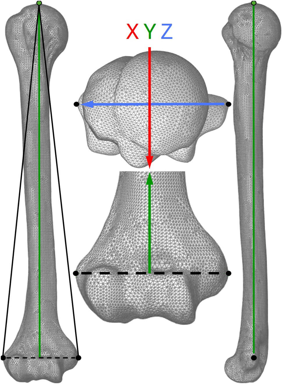
Alignment of the coordinate system of the computational humerus model according to recommendation of the International Society of Biomechanics on joint coordinate systems for the humerus. The triangular plane (left image) described by the lateral and medial epicondyle (black dots) and the highest point of the humeral head (green dot) represents the frontal plane. The y-axis (green arrow) presents the direction of axial loading.
Next, an alignment guide was designed and 3D printed. The guide adapts to the bone substitute and a cylindrical base of the test sample and ensures the correct axial orientation while the distal segment of the humerus was embedded in deep pour epoxy resin (ECO MAX System, EPODEX GmbH, Germany).
Test setup and load protocols
The test setup for axial loading, as seen in Figure 5, consisted of the test sample embedded in epoxy to a base mounted concentrically to the load axis of the test machine. The load was applied via a stamp with concave surface to lock translational movement in x- and z-direction but allow free rotation of the humeral head.
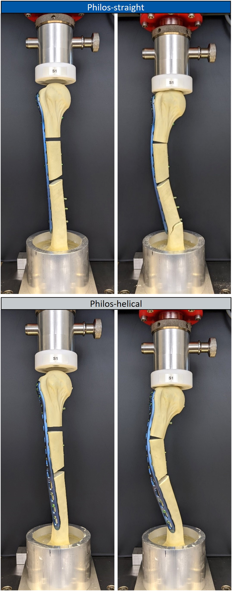
Test setup for axial static loading of the test sample group Philos-straight (top images) and Philos-helical (bottom images) in the unloaded state (left images) and the state of first failure under axial loading (right images).
Static testing was performed on a universal testing machine Z050 (ZwickRoell GmbH & Co. KG, Germany) equipped with a 5 kN load cell. The axial load was applied displacement controlled with 5 mm/min until complete failure. For static testing, six samples were tested in total, three for each test sample group.
Cyclic testing was performed on an electrodynamic testing machine LTM-5 (ZwickRoell GmbH & Co. KG, Germany) equipped with a 5 kN load cell. The cyclic load oscillated sinusoidally at 2 Hz for 100 k load cycles with a load maximum of 471 N and a load ratio of R=0.1. Additionally, a static intermediate test within the same load limits was conducted displacement controlled with 5 mm/min before the first cyclic loading and after every 10 k load cycles, to track the change in construct stiffness over time. The cyclic load protocol was performed on 12 samples in total, six samples for each test sample group. The test was stopped in case of a failure of the test sample.
For both test protocols, failure was defined if one of the following cases occurred: (1) fracture of the bone substitute; (2) failure of the implant system, e.g., cracking of a screw or the bone plate, screw loosening; (3) closure of a fracture gap in terms of a contact of the medial cortices.
Data acquisition
Output data of the test machines, such as axial displacement and load data, were recorded at 100 Hz and exported in csv-format. Data analysis was performed in Matlab® (Version R2024a) to calculate the axial construct stiffness. The axial construct stiffness was approximated using linear regression from the load-displacement data within the load range of 100 N and the physiological load limit of 471 N.
An Independent Student’s t-test (α=5 %) was performed to test for statistical significance in differences of axial construct stiffness between sample groups. In advance to significance analysis, the data was tested for normal distribution via the Shapiro-Wilk normality test.
Results
Torsional angle
The torsional deformation of the nine test samples of the Philos-helical test sample group resulted in a torsional angle of ϕ = (54.37±4.81)°.
Static testing
Test data analysis, displayed in Figure 6, resulted in a significant difference regarding the axial construct stiffness between the two sample groups (p=0.012), showing a 32.9 % higher mean in axial construct stiffness of Philos-straight compared to Philos-helical. Static testing led to an axial construct stiffness of 148.36±7.99 N/mm for Philos-straight, and 111.65±12.18 N/mm for Philos-helical.
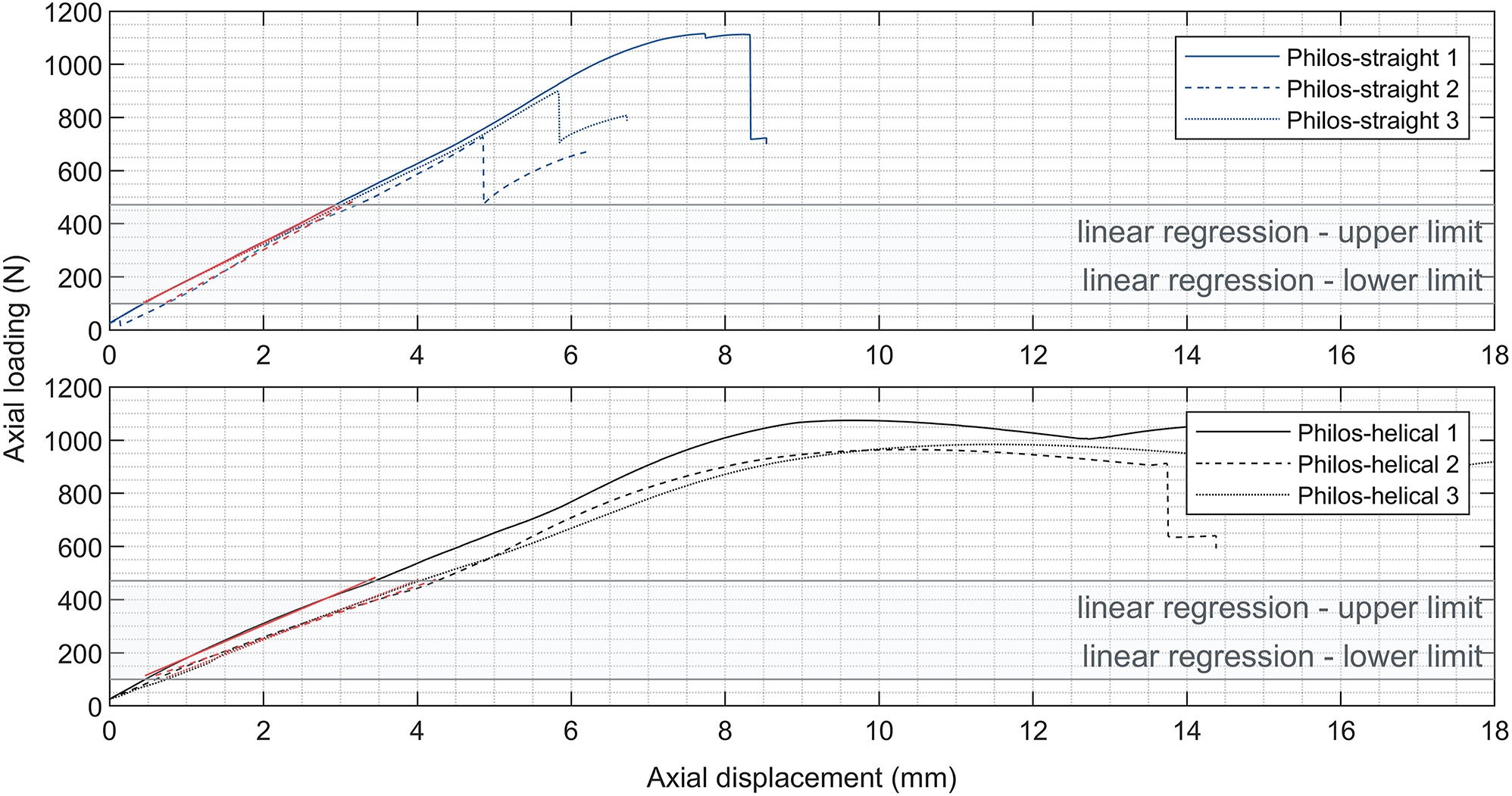
Load-displacement data of the control group Philos-straight (top chart) and Philos-helical (bottom chart) of the axial static load protocol to determine the axial construct stiffness represented by the approximated linear regression of the date (red slopes) in the predefined load range (grey shaded area) from 100 N to the physiological load limit of 471 N.
The Philos-straight samples failed abrupt due to failure of the bone substitute at the distal third under axial loading of 913.62±194.77 N. Test samples of Philos-helical failed in two stages, in which a closure of the fracture gap arose first, followed by a failure of the bone substitute at the distal third. The failure types can be seen in Figure 5.
Further could be observed, that the type of deformation of the test samples under axial load varied between sample groups. Philos-straight samples deformed laterally in-plane to the frontal plane. In contrast, samples of Philos-helical showed a combination of lateral and ventral deformation under axial loading. The resultant axial displacement at the physiological load of 471 N was approximately 28 % higher for Philos-helical compared to Philos-straight.
Cyclic testing
Testing was performed successfully according to the cyclic load protocol, leading to zero cases of failure in both test sample groups. Data of the static intermediate tests showed significant differences in axial construct stiffness between test sample groups before and in between cyclic loading (p≤0.010), as seen in Figure 7. The mean stiffness throughout each instance of static intermediate testing for each sample group showed a 22.96±1.86 % higher axial construct stiffness of Philos-straight to Philos-helical.
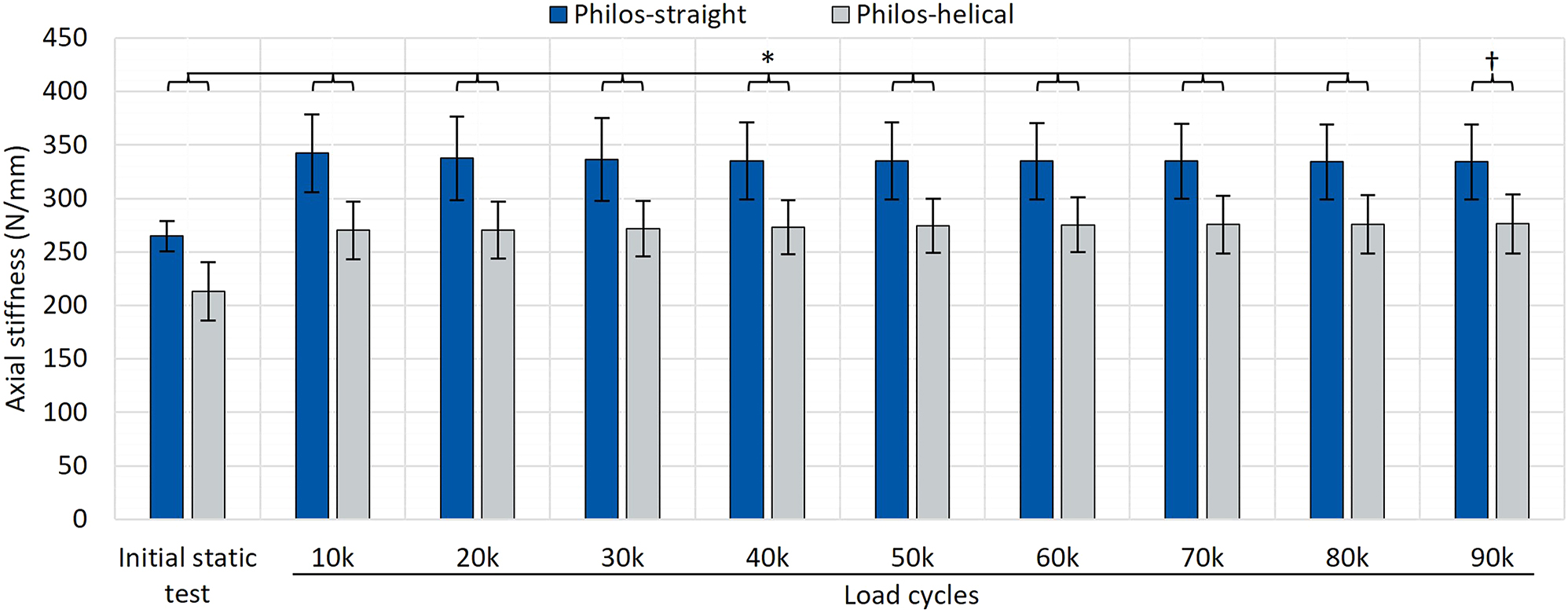
Test data of axial construct stiffness before and in between cyclic testing (after each 10 k load cycles at 10–90 k load cycles) resulting in significant differences between the test sample group Philos-straight (blue) and Philos-helical (grey). p-values: *p<0.010; †p=0.010.
Further could be observed, that the mean axial construct stiffness increased after 10 k load cycles compared to its initial value by +29.32 % for Philos-straight and +26.83 % for Philos-helical. After that, the axial construct stiffness remained comparable constant during cyclic loading.
The initial axial construct stiffness of cyclic test samples was higher compared to the static test samples, with 264.76±14.23 N/mm for Philos-straight and 213.09±27.43 N/mm for Philos-helical, showing a significant difference between bone substitutes in both test sample groups (p<0.001).
Discussion
In general, the torsional angle of a helically deformed plate depends mainly on the surgeon’s experience in adjusting the plate to the anatomy of the humerus as desired. Moreover, the torsional angle of Philos long plates to treat humeral fractures successfully via helical plating varies in literature between 45 and 90° and an optimal degree of torsion is not stated as recommendation [3], [8], [9], [10], [11], [12, 17], 19], 20]. Besides that, no study for helical plating measured the resulting torsional angle of helical deformed Philos plates precisely so far. The approach to determine the torsional angle via 3D scanning showed an effective method to measure the helical deformation in 3D space in terms of the dihedral angle. The result showed a mean torsional angle of approximately 54°, which is within the stated range of literature data. Also, a standard deviation of <5 % confirmed adequate comparability between samples of the sample group Philos-helical for each test scenario. Furthermore, this method could be applied to any deformed plating system.
No failure of samples under static and cyclic loading could be observed in both sample groups within the range up to the physiological axial load of 471 N. This finding can be considered plausible since there have been no reports of failures in the use of helical Philos plates in literature, which in turn would support their use in routine clinical practice.
As hypothesized, results of static and cyclic testing confirmed a lower axial construct stiffness for helical plating, resulting approximately in a 23 % lower axial construct stiffness for Philos-helical samples compared to Philos-straight. It was assumed that the change in stiffness is caused due to the plastic deformation and the associated material weakening at the section of plastic deformation. However, the main cause of the change in axial construct stiffness might not only be linked to a change in material properties, but also to the resulting deformation of the whole construct under axial load.
As described in the results, Philos-helical samples deformed in a combination of lateral and ventral motion, whereas Philos-straight samples deformed laterally in-plane of the frontal plane. This phenomenon is based on the biomechanics of the bone and the bone plate. The distal third of the humerus, where all samples failed consequently due to failure of the bone substitute, is in its anatomy asymmetric. Assuming a cross section with uniform material at the distal third, the area moment of inertia is approximately 1.5 times higher in medial-lateral direction than in dorsal-ventral direction. In case of pure bending, the humerus bends easier in dorsal-ventral direction than in medial-lateral direction under equal load condition at this section.
The same relation accounts for the rectangular cross section of the bone plate. In case of Philos-straight, the bone plate that is fixated laterally on the humerus favors lateral bending and restricts ventral bending throughout its length due to its rectangular cross section. In terms of Philos-helical, the proximal section of the helical bone plates favors lateral bending, whereas ventral bending is favored at the distal section due to the helical twist. Hence, the bending characteristics of the humerus and the helical plate favor a lateral-ventral deformation under axial loading. As a matter of fact, axial displacement was 28 % higher for Philos-helical than Philos-straight at the physiological axial load of 471 N.
Test data of the static intermediate tests in between cyclic loading showed a comparable ratio in axial construct stiffness between sample groups to the data of the static load protocol. Also, test data showed a proportional increase in axial construct stiffness after 10 k load cycles compared to the initial value. Since there were no additional changes in axial construct stiffness measured during cyclic loading, the proportional increase might be caused by settling of the test sample. For future cyclic IST, early changes of the samples’ properties should be tracked with higher resolution, e.g., at 10-100-1000 load cycles.
The lower axial construct stiffness of Philos-helical associates with an increased axial displacement that leads consequently to an increased interfragmentary movement (IFM), which is an important mechanobiological parameter and stimulus for bone healing [28]. However, promoted bone healing and tissue formation depend on specific ranges of magnitude and orientation of the resultant IFM [28]. Shear movements between fracture sides, as it might be present in case of Philos-helical due to the complex deformation of under axial loading, have a strong negative impact in bone healing [28]. Similar conclusions were made in the biomechanical studies for helical IST by Pastor et al. [19], 20]. An investigation regarding the bone healing relative to the different IFM of Philos-straight and Philos-helical would be highly interesting and will be part of further studies of the authorship.
In contrary to the presented results of this study, literature data by Pastor et al. [19], 20] showed no significant difference between straight and helical plating under static axial compression for an AO12C3 fracture on cadaveric and artificial bones. The difference in results might be based on the different boundary conditions of the test sample. Pastor et al. chose to mount the samples via cardan joints to the axial test setup, resulting in different degrees of freedom of the test sample. In this case, the rotational degree of freedom around the load axis (y-axis) is blocked and only bending moments can occur.
The results of the presented study are based on physiological 1D axial loading. However, the OrthoLoad® data can also be analyzed regarding multidimensional joint loads. Therefore, it would be reasonable to extend the load scenarios to compare the biomechanical performance of Philos-straight and Philos-helical under 2D/3D static and cyclic loading. In that context, an in-silico analysis in Ansys® would be suited for further studies, as a time- and cost-efficient alternative to actual testing, since the computational scan models of the humerus are already available. Advanced in-silico analysis using musculoskeletal models to address a complex load scenario of the acting muscles of the humerus would be another valid approach for further investigations.
Systematic literature reviews regarding humeral IST describe the regular use of artificial bones in static and cyclic testing as an alternative for human cadaver bones [21], 29]. However, Becker et al. [25] presented an unrealistic early failure scenario for Synbone® in case of torsional cyclic loading. To reduce the risk of an unrealistic early failure under axial cyclic loading, test samples for the cyclic load protocol featured Sawbones®, whereas test samples for the static load protocol featured Synbone®. Since both test protocols determined the axial construct stiffness under equal setup and load condition for each sample group, a potential difference between samples with Sawbones® and Synbones® originates from a different axial stiffness of the bone substitutes. Test data revealed a significantly higher axial construct stiffness for test samples featuring Sawbones® within both test sample groups, showing an average of +78 % for Philos-straight and even +90 % for Philos-helical. The low axial stiffness of Synbone® might have led to early failure under axial cyclic loading as assumed. In general, this outcome illustrates the difficulty of comparability in the field of IST. Literature data can hardly be compared to one another if parameters such as the choice of artificial bone substitutes influence values in that dimension. A biomechanical guideline should be established to generalize procedures for IST in specific fields and applications.
As a limitation of this study, it needs to be pointed out that the presented results rely on the specific load case scenario and the osteosynthetic plating system PHILOS® Long with the specific configurations of the test samples of Philos-straight and Philos-helical. Other helically deformed osteosynthetic systems might conclude in different results in case of the presented test scenario, as configuration parameters such as the material, form, screw configuration and number of screws might impact the axial construct stiffness and the related deformation significantly.
Despite the absence of a declaration regarding helical deformation as an intended use in the instructions for use of the osteosynthetic system PHILOS® Long, Philos-helical resulted in no failure under static and cyclic testing within the physiological load boundaries. In terms of a clinical implication, this study’s outcome indicates sufficient biomechanical stability to withstand the applied load scenario as a post-operative daily routine. To the current knowledge based on the presented paper and previously conducted clinical studies, the advantages of helical plating with PHILOS® Long present a valid alternative to the conventional straight plating technique for proximal humeral shaft fractures, as it offers sufficient biomechanical performance and the prevention of iatrogenic radial nerve damage at the same time [11], [14], [15], [16], [17], [18], [19], [20].
To the authorships knowledge, there is only one osteosynthetic system on the market addressing helical bending as a feature of the intended use – the A.L.P.S.® Proximal Humerus Plating System (Zimmer Biomet, Warsaw, IN, USA). A biomechanical comparison between a helically deformed PHILOS® Long system and the A.L.P.S.® system under equal torsional deformation and test scenarios for static and cyclic loading would be highly interesting.
Acknowledgments
The authors thank the whole research team and supporters for its teamwork.
-
Research ethics: Not applicable.
-
Informed consent: Not applicable.
-
Author contributions: All authors have accepted responsibility for the entire content of this manuscript and approved its submission.
-
Use of Large Language Models, AI and Machine Learning Tools: None declared.
-
Conflict of interests: The authors state no conflict of interest.
-
Research funding: No funding is linked to this work.
-
Data availability: Not applicable.
References
1. Gill, DRJ, Torchia, ME. The spiral compression plate for proximal humeral shaft nonunion: a case report and description of a new technique. J Orthop Trauma 1999;13:141–4. https://doi.org/10.1097/00005131-199902000-00013.Search in Google Scholar PubMed
2. Claessen, FMAP, Peters, RM, Verbeek, DO, Helfet, DL, Ring, D. Factors associated with radial nerve palsy after operative treatment of diaphyseal humeral shaft fractures. J Shoulder Elbow Surg 2015;24:e307–11. https://doi.org/10.1016/j.jse.2015.07.012.Search in Google Scholar PubMed
3. Dauwe, J, Grechenig, P, Unterfrauner, I, Schwarz, A, Weiglein, A, Hohenberger, G. Axillary nerve elongation in humeral fracture plating: a cadaveric study for comparison between straight and helical Philos plates. J Orthop 2020;19:233–6. https://doi.org/10.1016/j.jor.2020.02.009.Search in Google Scholar PubMed PubMed Central
4. Kettelkamp, DB, Alexander, H. Clinical review of radial nerve injury. J Trauma 1967;7:424–32. https://doi.org/10.1097/00005373-196705000-00007.Search in Google Scholar PubMed
5. Kim, JW, Oh, C-W, Byun, Y-S, Kim, JJ, Park, KC. A prospective randomized study of operative treatment for noncomminuted humeral shaft fractures: conventional open plating versus minimal invasive plate osteosynthesis. J Orthop Trauma 2015;29:189–94. https://doi.org/10.1097/bot.0000000000000232.Search in Google Scholar
6. Schwab, TR, Stillhard, PF, Schibli, S, Furrer, M, Sommer, C. Radial nerve palsy in humeral shaft fractures with internal fixation: analysis of management and outcome. Eur J Trauma Emerg Surg 2018;44:235–43. https://doi.org/10.1007/s00068-017-0775-9.Search in Google Scholar PubMed PubMed Central
7. van de Wall, BJM, Ganzert, C, Theus, C, van Leeuwen, RJH, Link, BC, Babst, R, et al.. Results of plate fixation for humerus fractures in a large single-center cohort. Arch Orthop Trauma Surg 2020;140:1311–18. https://doi.org/10.1007/s00402-019-03319-z.Search in Google Scholar PubMed
8. Arumilli, B, Suhm, N, Marcel, J, Rikli, D. Long PHILOS plate fixation in a series of humeral fractures. Eur J Orthop Surg Traumatol 2014;24:1383–7. https://doi.org/10.1007/s00590-013-1324-9.Search in Google Scholar PubMed
9. Pastor, T, Kastner, P, Souleiman, F, Gehweiler, D, Migliorini, F, Link, B-C, et al.. Anatomical analysis of different helical plate designs for proximal humeral shaft fracture fixation. Eur J Trauma Emerg Surg 2023;49:411–18. https://doi.org/10.1007/s00068-022-02082-y.Search in Google Scholar PubMed
10. Da Silva, T, Rummel, F, Knop, C, Merkle, T. Shoulder function after helical long PHILOS plate. Eur J Orthop Surg Traumatol 2021;31:1463–9. https://doi.org/10.1007/s00590-021-02908-2.Search in Google Scholar PubMed
11. García-Virto, V, Santiago-Maniega, S, Llorente-Peris, A, Simón-Pérez, C, Álvarez-Ramos, BA, García-Florez, L, et al.. MIPO helical pre-contoured plates in diaphyseal humeral fractures with proximal extension. Surgical technique and results. Injury 2021;52:S125–30. https://doi.org/10.1016/j.injury.2021.01.049.Search in Google Scholar PubMed
12. Wang, Q, Xu, Y, Wang, Y, Zhang, S, Chen, Y, Wang, L. Tips and tricks of long helical PHILOS plating on proximal humeral diaphyseal and metaphyseal fractures using the MIPO technique in elderly patients: a cadaveric study and clinical experience. Int J Clin Exp Med 2017;10:6489–95.Search in Google Scholar
13. Yang, KH. Helical plate fixation for treatment of comminuted fractures of the proximal and middle one-third of the humerus. Injury 2005;36:75–80. https://doi.org/10.1016/j.injury.2004.03.023.Search in Google Scholar PubMed
14. Da Silva, T, Rummel, F, Knop, C, Merkle, T. Comparing iatrogenic radial nerve lesions in humeral shaft fractures treated with helical or straight PHILOS plates: a 10-year retrospective cohort study of 62 cases. Arch Orthop Trauma Surg 2020;140:1931–7. https://doi.org/10.1007/s00402-020-03438-y.Search in Google Scholar PubMed
15. Moon, J-G, Kwon, H-N, Biraris, S, Shon, W-Y. Minimally invasive plate osteosynthesis using a helical plate for metadiaphyseal complex fractures of the proximal humerus. Orthopedics 2014;37:e237–43. https://doi.org/10.3928/01477447-20140225-55.Search in Google Scholar PubMed
16. Tan, JCH, Kagda, FHY, Murphy, D, Thambiah, JS, Khong, KS. Minimally invasive helical plating for shaft of humerus fractures: technique and outcome. Open Orthop J 2012;6:184–8. https://doi.org/10.2174/1874325001206010184.Search in Google Scholar PubMed PubMed Central
17. Wang, Q, Hu, J, Guan, J, Chen, Y, Wang, L. Proximal third humeral shaft fractures fixed with long helical PHILOS plates in elderly patients: benefit of pre-contouring plates on a 3D-printed model-a retrospective study. J Orthop Surg Res 2018;13:203. https://doi.org/10.1186/s13018-018-0908-9.Search in Google Scholar PubMed PubMed Central
18. Brunner, A, Thormann, S, Babst, R. Minimally invasive percutaneous plating of proximal humeral shaft fractures with the proximal humerus internal locking system (PHILOS). J Shoulder Elbow Surg 2012;21:1056–63. https://doi.org/10.1016/j.jse.2011.05.016.Search in Google Scholar PubMed
19. Pastor, T, Zderic, I, Drenchev, L, Skulev, HK, van Knegsel, KP, Lenz, M, et al.. Helical plating compared with straight plating and nailing for treatment of proximal third humeral shaft fractures-A biomechanical study. Medicina 2023;59:2043. https://doi.org/10.3390/medicina59112043.Search in Google Scholar PubMed PubMed Central
20. Pastor, T, Zderic, I, van Knegsel, KP, Beeres, FJP, Migliorini, F, Babst, R, et al.. Biomechanical analysis of helical versus straight plating of proximal third humeral shaft fractures. Arch Orthop Trauma Surg 2023;143:4983–91. https://doi.org/10.1007/s00402-023-04814-0.Search in Google Scholar PubMed
21. Halbauer, C, Capanni, F, Bertusch, I, Paech, A, Merkle, T, Da Silva, T. Biomechanical testing of osteosynthetic locking plates for proximal humeral shaft fractures - a systematic literature review. Biomed Eng 2023;68:553–61. https://doi.org/10.1515/bmt-2023-0039.Search in Google Scholar PubMed
22. Bergmann, G, Graichen, F, Bender, A, Rohlmann, A, Halder, A, Beier, A, et al.. In vivo gleno-humeral joint loads during forward flexion and abduction. J Biomech 2011;44:1543–52. https://doi.org/10.1016/j.jbiomech.2011.02.142.Search in Google Scholar PubMed
23. Westerhoff, P, Graichen, F, Bender, A, Rohlmann, A, Bergmann, G. An instrumented implant for in vivo measurement of contact forces and contact moments in the shoulder joint. Med Eng Phys 2009;31:207–13. https://doi.org/10.1016/j.medengphy.2008.07.011.Search in Google Scholar PubMed
24. Meinberg, EG, Agel, J, Roberts, CS, Karam, MD, Kellam, JF. Fracture and dislocation classification compendium-2018. J Orthop Trauma 2018;32:S1–170. https://doi.org/10.1097/bot.0000000000001063.Search in Google Scholar
25. Becker, EH, Kim, H, Shorofsky, M, Hsieh, AH, Watson, JD, OʼToole, RV. Biomechanical comparison of cadaveric and commercially available synthetic osteoporotic bone analogues in a locked plate fracture model under torsional loading. J Orthop Trauma 2017;31:e137–42. https://doi.org/10.1097/bot.0000000000000782.Search in Google Scholar
26. Schmidt, J, Riedel, T, Grundler, S, editors. Nachbehandlungsempfehlungen 2023: Arbeitskreis Nachbehandlungsempfehlungen, Sektion Rehabilitation Physikalische Therapie. Berlin: Deutsche Gesellschaft für Orthopädie und Unfallchirurgie (DGOU); 2023.Search in Google Scholar
27. Wu, G, van der Helm, FCT, Veeger, HEJD, Makhsous, M, van Roy, P, Anglin, C, et al.. ISB recommendation on definitions of joint coordinate systems of various joints for the reporting of human joint motion--Part II: shoulder, elbow, wrist and hand. J Biomech 2005;38:981–92. https://doi.org/10.1016/j.jbiomech.2004.05.042.Search in Google Scholar PubMed
28. Claes, LE. Mechanobiology of fracture healing: from basic science to clinical application. Cham: Springer International Publishing; 2022.10.1007/978-3-030-94082-9Search in Google Scholar
29. Cruickshank, D, Lefaivre, KA, Johal, H, MacIntyre, NJ, Sprague, SA, Scott, T, et al.. A scoping review of biomechanical testing for proximal humerus fracture implants. BMC Musculoskelet Disord 2015;16:175. https://doi.org/10.1186/s12891-015-0627-x.Search in Google Scholar PubMed PubMed Central
© 2024 the author(s), published by De Gruyter, Berlin/Boston
This work is licensed under the Creative Commons Attribution 4.0 International License.
Articles in the same Issue
- Frontmatter
- Review
- Hydrogel promotes bone regeneration through various mechanisms: a review
- Research Articles
- Wear investigation of implant-supported upper removable prothesis with electroplated gold or PEKK secondary crowns
- Straight and helical plating with locking plates for proximal humeral shaft fractures – a biomechanical comparison under physiological load conditions
- Integration of neuromuscular control for multidirectional horizontal planar reaching movements in a portable upper limb exoskeleton for enhanced stroke rehabilitation
- Recognition analysis of spiral and straight-line drawings in tremor assessment
- Combination of edge enhancement and cold diffusion model for low dose CT image denoising
- High-performance breast cancer diagnosis method using hybrid feature selection method
- A multimodal deep learning-based algorithm for specific fetal heart rate events detection