Experimental and numerical investigations of fracture and fatigue behaviour of implant-supported bars with distal extension made of three different materials
-
Jennifer Mochalski


Abstract
The aim of this study was to investigate experimentally the fatigue and stability of three bar materials with distal extension at the molar region and to numerically analyse the biomechanical properties of the bar materials connected to overdentures in a patient individual model. A milled bar was designed for the mandible on four implants in the canine and second premolar region. Three bar materials were investigated: titanium (Ti), cobalt chromium (CoCr), and polyetherketonketon (PEKK). Firstly, static and fatigue tests were performed based on EN ISO 14801 in a commercial permanent loading set-up. Unilateral axial force was applied on the distal extension of the bars. Secondly, numerical models were created. Different bar materials and loading scenarios were analysed. The static fracture limit of the three materials was 1,750 N, 780 N, 310 N for Ti, CoCr, and PEKK, respectively. The Wöhler curves showed comparable fatigue limits of 200 N, 160 N, and 150 N for titanium, CoCr, and PEKK, respectively. The stress at the distal extension was 2,600 MPa (Ti), 1,000 MPa (CoCr), and 270 MPa (PEKK). All loading simulations with the PEKK bar showed higher stresses in the implants and in the bone bed as well as higher displacements of the over denture in comparison to metal bars. PEKK showed different mechanical behaviour compared to Ti and CoCr. The distribution of stresses within the PEKK bar was wider than the area of loading which probably leads to fatigue of the whole bar and not only the part under load.
Introduction
Edentulous patients with a complete denture very often report on poor retention and stability, continuous pressure lesions [1] as well as impaired masticatory function [2]. This situation could have negative influence on the social life [3]. For higher patient satisfaction, better chewing ability, aesthetics, denture stability and phonetics, an implant-supported overdenture offers a very good alternative to a complete denture [1], [4]. There are different modalities for the connection between implants and overdentures [5]. Bar and ball attachments provide the highest patient satisfaction in retaining an overdenture [6]. Provided a sufficient primary stability of the implants can be achieved, it is possible to use a bar to support a restoration immediately after implant insertion [7]. One further benefit of a bar is a favourable stability of the denture over it [8]. Combining the bar and clip attachments reduces the loading forces on the implants and helps compensating misaligned implants. The bar splints the implants and the clip positions the lower surface of the prosthesis. This offers a high retentive capacity [9].
The oldest bar material are gold alloys. This material proves to be highly biocompatible and stable. However, high costs reduced its application in the last years. Alternative materials are titanium (Ti) or non-precious metal alloys like cobalt chromium (CoCr) alloy [10]. Furthermore there are various kinds of bars, such as round clip bars, ovoid-shaped bars, or parallel wall-shaped bar designs [11]. A good compromise is a rigid anchorage with milled bars on four implants supporting the prostheses [12]. Moreover, bilateral distal extensions are a good option to improve retention and stability of the overdenture [13]. For retaining the overdenture on the bar, metallic as well as plastic clips are used [14], [15], [16].
Obviously, there is no lack of variety in materials for producing bars. However, there is a high demand for non-metal materials, especially for patients with a metal allergy. A larger number of those patients showed a higher sensitisation to cobalt and nickel [15]. Polyetherketoneketone (PEKK) is a high performance polymer belonging to the polyaryletherketone (PAEK) family. Several recent studies showed that the elasticity, fatigue strength, bending properties as well as a good wear and abrasion resistance are positive properties of this material [16], [17].
In dentistry, PEKK is a novel material and the application in dental treatment is still not well investigated. This study presents one possible application of PEKK to show whether this material could offer more alternatives for patients with metal allergy and patients preferring non-metal restorations. PEKK could be used as a framework material for fixed dental restorations as well as for removable dentures on implants and teeth [18]. In comparison to metal bars, PEKK is a cheaper alternative with respect to manufacturing, however, PEKK cannot be repaired over time and in case of fracture of a PEKK framework, a completely new replacement has to be milled.
The aim of this study was to investigate experimentally the fatigue and stability of bar extensions in the molar region depending on the bar material (Ti, CoCr, PEKK). Additionally, this study aimed to numerically investigate the biomechanical properties of different bar materials in combination with implant-supported overdentures in a patient individual finite element model.
Materials and methods
Experimental investigation (Fracture and Fatigue load)
A milled bar design for the lower edentulous jaw on four implants was considered in this study. Implants were positioned in the canine and second premolar region. The bar was designed with a distal extension in the first molar region. The used implant system was tioLogic©-ST (Ø4.2 mm, L13 mm, abutment type M, GH 2.5 mm, Dentaurum Implants GmbH, Ispringen, Germany). Three framework materials were investigated in this study: titanium grade 5 (induDENT AG, Duisburg, Germany), non-precious alloy (CoCr, induDENT AG, Duisburg, Germany), and PEKK (Pekkton® ivory, Cendres + Métaux SA, Biel/Bienne, Switzerland).
The test model with the implants was scanned using an Imetric Dental Scanner (Imetric4D, Courgenay, Switzerland) in order to have the geometry in a digital form. Later on, the bars were designed using Exocad Software (Exocad GmbH, Darmstadt, Germany). The design of the metal and PEKK bars was based on the typical clinical applications on patients and according to the recommendation of the manufacturer regarding the geometry and the required minimal thickness of the material at the different regions of the bar. The metal bars were milled using WM408MT (Willemin-Macodel SA, Delémont, Switzerland). The PEKK bars were milled from Pekkton® ivory milling blanks using a VhF table milling machine (VhF, Ammerbuch, Germany). Finally, all bars were finished and polished to the final dimension.
Three groups of specimens were investigated: Ti bars, CoCr bars, and PEKK bars. The dimension of Ti and CoCr bars were identical and constructed according to the clinical indications (material thickness at the abutment was 1.0 mm, bar thickness 2.3 mm, and bar height was 3.0 mm, Figure 1A). The length of the distal extensions for titanium and CoCr bars was 10.0 mm.

The design of the bars used in this study: (A) Ti and CoCr Bar, and (B) PEKK bar. The PEKK bar is designed according to the clinical recommendations with Ti abutments.
The design of the PEKK bar differed from this and the thickness of the material at the abutment was higher than with the other two materials, according to the clinical indication in order to provide sufficient material stability (material thickness at the abutment was 1.5 mm, bar thickness 2.5 mm, and bar height was 4.0 mm, Figure 1B). The length of the distal extension for the PEKK bars was 7.6 mm. Although the length of the distal extension of the three materials seems to be different, the distance from the mid of the distal implant to the bar end was identical for all three bar designs.
For the static fracture and fatigue testing, the four implants supporting the bars were embedded in an aluminum holder that included four bores with a diameter of 18 mm using a resin (Pala-Xpress, Heraeus Kulzer GmbH, Germany). The resin had a Young’s modulus of 3.0 GPa. Based on EN ISO 14801 the implants were embedded at a height of 3 mm below the implant shoulder and the bar was mounted on the implants (Figure 2). For each group, the static fracture limit of the bars was determined in static fracture tests on the left and right extensions of 19 specimens, respectively, using a commercial materials testing machine (ZMART.PRO, Zwick GmbH & Co. KG, Ulm, Germany).
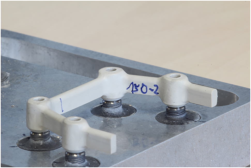
The implants were embedded in a resin 3 mm below the implant shoulder.
The fatigue tests of the bars were performed using a commercial electro-pneumatic set-up (“Dyna-Mess TP 5 kN HF”, DYNA-MESS Prüfsystem GmbH, Germany). Unilateral force was applied axially on the distal extension of the bar (Figure 3), i.e., for each bar, the fatigue test was done on the right and the left distal extensions, successively. The position of the load application was identical for all three materials and based on the distance from the mid of the distal implant to the point of load application.

The position of the applied unilateral axial force on the distal extension of the bar.
80% of the determined fracture limits was chosen as initial force level for fatigue testing, as required by EN ISO 14801. During fatigue testing, the force should alternate between the nominal load and 10% of this value with sinus-shaped amplitude. This sinus-shaped amplitude and the 10% lower limit are requested by EN ISO 14801 as well.
At each force level, at least two (preferable three) specimens had to be tested, and if at least one specimen failed fatigue loading at this level, an additional, lower force level had to be tested. At least, four different force levels should be tested in total. For all force levels, the force alternated between the maximum force and 10% of the maximum force. Measurements were continued with decreasing forces until a lower limit was reached at which all tested specimens survived fatigue testing. In this case, a minimum of three specimens was required to be tested at this force level. A loading frequency of 2 Hz and a total of 2×10⁶ loading cycles were used for each bar (according to EN ISO 14801).
Due to the requirements of EN ISO 14801, the number of bars for each framework material was different. For this reason, six bars for titanium, six bars for PEKK, and seven bars for CoCr were milled for this investigation. For all tests, a specimen was considered to have failed fatigue testing, if either a fracture occurred, or a crack was visible in the bar.
Analysis of the experimental results
Based on the data gained from the fatigue tests for all three groups, Wöhler curves were generated based on EN ISO 14801. The number of specimens per group and force level was not high enough to perform a statistical analysis to determine possible significant differences between the three groups.
Comparison of the experimental and numerical investigation
Three 3-dimensional finite element (FE) models were created to simulate the experimentally tested bar materials. The models consisted of a bar (Ti, CoCr, and PEKK) with distal extensions, four implants, a holder for the implants, and a stamp. CAD/CAM data for the original bars, abutments and implants were provided from the manufacturers (from the experimental part of this study) to create the models (Figure 4A). The FE models for Ti and CoCr bars were identical, only the material properties were verified. The PEKK bar had a bonded interface to the Ti abutments, whereas the Ti and CoCr bars had a one-piece screwed design (Figure 4B). Segmentation, matching and positioning of the different components of the model were done using 3-matic research programme (3-matic Research 11.0, Materialise, Leuven, Belgium). After completion of the meshing of the models, they were imported into the FE program MSC.Marc/Mentat 2010 (Santa Ana, CA, USA) and material properties (Table 1) as well as boundary conditions were defined. Young’s modulus (in MPa) and Poisson’s ratio of the materials used were based on the information given by the manufacturer. Homogeneous and isotropic 4-noded tetrahedral elements were considered for all models. The final models were composed of up to 349,306 elements and 83,811 nodes.

(A) Finite element models of the three bar materials based on the experimental set-up. (B) A zoomed view for the bars and their connection to the implants.
Material properties used for the comparison to the experimental set up.
| Structure/Material | Young’s modulus, MPa | Poisson’s ratio |
|---|---|---|
| Stamp, Steel | 200,000 | 0.30 |
| Implants (bar), Ti alloy (Grade 5) | 110,000 | 0.30 |
| Bar, CoCr | 250,000 | 0.30 |
| Bar, PEKK | 5,100 | 0.38 |
| Holder, PMMA | 3,300 | 0.39 |
A unilateral axial load was applied on the distal extension of the bar (Figure 4). The magnitude of the forces was obtained from the statically load that was observed experimentally for each material: 1,750 N, 780 N, and 310 N for Ti, CoCr, and PEKK, respectively. The base of the model was constrained in all three degrees of freedom.
Numerical investigations based on a patient individualised model
The second part of this study consisted of the simulation of a clinical situation with the different bar materials for an edentulous mandible in order to analyse the influence of the bar material on the stability of the mounted denture. Additionally the load distribution in the implants and the surrounding bone were investigated. Noticeable difference in the loading behaviour of the implants and the bone in relation to the bar material were expected.
Based on the above-mentioned three 3D-models, an edentulous mandible with implant-supported overdentures and implants was generated. The connection of the overdenture to the four implants was realised by a bar/clips attachment system. The models consisted of four implants in the canine and second premolar region, bars/clips (Ti, CoCr, PEKK) and an edentulous mandible (cortical bone, spongious bone), mucosa, and overdenture (Figure 5). Data processing of the implants and bars was the same as described in 2.2. The geometries of the edentulous mandible and the overdenture were based on patient’s data (ethical committee of the University of Bonn; No. 258/12). The geometry of the original overdenture was generated by scanning the dentures using the 3shape Lab Scanner (3shape, Heraeus Kulzer GmbH, Hanau, Germany). Three clips were created with the 3-matic software in the centre of the three parts of the bar (Figure 5). The clips had a height of 2.8 mm, a width of 2.2 mm, a length of 2.5 mm, and a thickness of 0.3 mm.

Finite element individual model for an overdenture supported by four implants and bar anchor system.
The connection between the bar and the clips corresponded to the Dolder system construction (Cendres + Métaux SA, Biel/Bienne, Switzerland). The clips were considered to be fixed to the inner side of the overdenture. One clip was located in the front segment and two clips were located in the segment between the canine and second premolar on each side. Subsequently, the models were imported into MSC.Marc/Mentat 2010 to define the material properties (Table 2) and boundary conditions. The Young’s modulus in MPa and Poisson’s ratio of the used materials were based on manufacturers’ information (metal and resin) and from literature (bone and mucosa) [19]. The final models were composed of up to 456,311 elements and 105,047 nodes.
Material properties of the patient’s individual models.
| Structure | Young’s modulus, MPa | Poisson’s ratio |
|---|---|---|
| Cortical bone | 20,000 | 0.30 |
| Spongious bone | 1,000 | 0.30 |
| Mucosa | 1 | 0.37 |
| Ti alloy (Grade 5) | 110,000 | 0.30 |
| CoCr | 250,000 | 0.30 |
| PEKK | 5,100 | 0.38 |
| Overdenture, PMMA | 3,300 | 0.39 |
The implants were considered as fully osseointegrated and therefore no contact at the bone/implant interface was defined. Since the analysis of the inner connection between the implant and the abutment was not the focus in this study, the inner connection was considered to be optimal and glued contact was defined between the implants and the abutments. A sliding contact was defined between clips and bar and between overdenture and mucosa. Contact parameters were adjusted as follows: For sliding contact coulomb friction with a frictional coefficient of 0.5 and a nonlinear smoothing function based on relative sliding velocity was used. A threshold of 10% was used to differentiate between stick and slip. Glued contact was realised by a tight connection between all individual components of the model.
Boundary conditions for the patient individualised model
For each model (Ti, CoCr, PEKK), four different loading scenarios were simulated (Figure 6):
Scenario 1: Axial bilateral loading on the overdenture in the first molar region.
Scenario 2: Non-axial bilateral loading on the overdenture in the first molar region with an angle of 30° from the long axis of the overdenture toward vestibular direction.
Scenario 3: Axial bilateral loading on the overdenture in the first molar region and non-axial bilateral loading in the canine region with 30° from the long axis of the overdenture toward vestibular direction.
Scenario 4: Non-axial bilateral loading on the overdenture in the first molar and the canine regions with an angle of 30° from the long axis of the overdenture toward vestibular direction.

Loading scenarios that were simulated for the individual model.
The applied loads were 50 and 300 N [20] in the canine and the first molar regions, respectively.
For the experimental visualisation, one more scenario for each model (Ti, CoCr, PEKK) was simulated. The magnitude of the experimentally obtained statical loads was applied axially on the corresponding model: 1,740 N, 780 N, and 310 N for Ti, CoCr, and PEKK, respectively. Furthermore, in every loading scenario, the clip material (Ti, CoCr, PEKK) was varied. The mandible was constrained in three degrees of freedom at the angle of the mandible.
Results
Experimental results
Static Fracture Tests
There was a noticeable difference for the fracture behaviour of the three materials (Ti: 1,750 N, CoCr 780 N, PEKK 310 N). For the titanium distal extension, only permanent deformation occurred, whereas for the other two materials cracks and fracture was observed.
Fatigue Tests
The Wöhler curves (Figure 7) showed comparable fatigue limits of 200 N, 160 N, and 150 N for Ti, CoCr, and PEKK bars, respectively. A summary of the performance of the different specimens for the three different materials can be seen in Figure 8. For Ti the force level for the bar extension survival after 2×10⁶ cycles was 200 N. All three extensions survived at this force level. The number of bar extensions that partially cracked under the fatigue test was 1, 2, 2, and 2 at a force level of 1,400 N, 1,100 N, 800 N, and 400 N, respectively.

Wöhler curves as determined in the fatigue tests for the three different bar materials.

Performance of the tested specimens for all three materials.
For CoCr, the force level for the bar extension survival after 2×10⁶ cycles was 160 N for three bars. One bar extension survived at a force level of 320 N and one bar extension at a force level of 240 N. The number of bar extensions that partially cracked under the fatigue test was 2, 2, and 1 at a force level of 480 N, 320 N, and 240, respectively. One bar extension showed plastic deformation at a force level of 640 N.
For PEKK, the first tested force levels were 240 N, 180 N, and 120 N. As all specimens survived at a force of 120 N and a sufficient number of specimens were still available, an additional force level of 150 N (in the middle of 180 and 120 N) was introduced. All three tested specimens with 150 N survived after 2×10⁶ cycles as well. The number of bar extensions that totally fractured during the fatigue test was 3 and 2 at a force level of 180 and 240 N, respectively.
Numerical results
Comparison of the Experimental and Numerical Results
Displacement of the Bar
After the unilateral axial load on the distal extension of the bars (Ti 1,750 N, CoCr 780 N, PEKK 310 N), the Ti bar displayed a displacement of 0.82 mm. In comparison to the CoCr bar (0.22 mm) the displacement was 4 times higher. The PEKK bar showed a displacement of 0.51 mm.
Stress in Bar and Implants
In comparison to the Ti bar, the stress in the distal extension of the PEKK bar was higher (270 MPa compared to 2,600 MPa), whereas the CoCr bar had a stress of 1,000 MPa. The stresses in the implants under axial load displayed higher values with the Ti bar than with the PEKK bar (3,100–430 MPa) as well. The model with the CoCr bar showed a maximum stress of 1,300 MPa within the implants (Figure 9).

Stresses in the bar and implants based on the experimental fracture load.
Numerical investigations based on patient individualised model
Displacement of the Overdenture
Irrespective of the kind and magnitude of loading, the displacement of the overdenture showed higher values with the PEKK bar in comparison to the other bar materials. For instance, the displacement of the overdenture under non-axial loading in the molar region was 0.40, 0.35, and 0.89 mm with Ti, CoCr, and PEKK bars, respectively. The displacements of the overdentures are illustrated in Figure 10 and listed in Table 3.

Displacement of the overdenture obtained with different bar materials and different loading scenarios.
Numerical results of the patient’s individual models.
| Ti bar | CoCr bar | PEKK bar | |||||||
|---|---|---|---|---|---|---|---|---|---|
| Clip material | Ti | CoCr | PEKK | Ti | CoCr | PEKK | Ti | CoCr | PEKK |
| Displacement of the overdenture, mm | |||||||||
| Scenario 1 | 0.30 | 0.30 | 0.31 | 0.27 | 0.27 | 0.28 | 0.86 | 0.86 | 0.84 |
| Scenario 2 | 0.40 | 0.39 | 0.42 | 0.36 | 0.35 | 0.37 | 0.88 | 0.88 | 0.89 |
| Scenario 3 | 0.40 | 0.40 | 0.42 | 0.36 | 0.35 | 0.37 | 0.87 | 0.87 | 0.88 |
| Scenario 4 | 0.28 | 0.28 | 0.29 | 0.26 | 0.26 | 0.27 | 0.84 | 0.84 | 0.85 |
| Stress in the bar, MPa | |||||||||
| Scenario 1 | 400 | 400 | 460 | 400 | 450 | 450 | 80 | 81 | 80 |
| Scenario 2 | 250 | 255 | 280 | 370 | 360 | 370 | 80 | 78 | 81 |
| Scenario 3 | 320 | 320 | 300 | 360 | 350 | 380 | 94 | 95 | 97 |
| Scenario 4 | 380 | 370 | 700 | 370 | 365 | 400 | 80 | 81 | 83 |
| Stress in the implants, MPa | |||||||||
| Scenario 1 | 180 | 190 | 185 | 180 | 180 | 180 | 210 | 210 | 200 |
| Scenario 2 | 160 | 155 | 140 | 175 | 180 | 170 | 220 | 220 | 220 |
| Scenario 3 | 160 | 155 | 190 | 155 | 150 | 150 | 220 | 230 | 230 |
| Scenario 4 | 130 | 130 | 135 | 140 | 140 | 130 | 230 | 230 | 230 |
| Stress in the clips, MPa | |||||||||
| Scenario 1 | 200 | 225 | 110 | 180 | 185 | 100 | 130 | 160 | 70 |
| Scenario 2 | 180 | 195 | 130 | 185 | 210 | 170 | 170 | 135 | 75 |
| Scenario 3 | 180 | 195 | 115 | 170 | 200 | 155 | 140 | 150 | 65 |
| Scenario 4 | 180 | 200 | 105 | 170 | 200 | 100 | 130 | 150 | 55 |
| Stress in the bone bed around the implants, MPa | |||||||||
| Scenario 1 | 30 | 30 | 30 | 30 | 30 | 25 | 55 | 55 | 53 |
| Scenario 2 | 30 | 33 | 25 | 30 | 30 | 27 | 60 | 60 | 60 |
| Scenario 3 | 30 | 30 | 38 | 30 | 30 | 27 | 50 | 55 | 56 |
| Scenario 4 | 30 | 30 | 25 | 35 | 35 | 33 | 53 | 54 | 54 |
Stresses in the bar
Stresses in the Ti and CoCr bars were higher in all load scenarios and with various clip materials than in the PEKK bar. For instance, the stress in the bar under axial loading at the molar region was 460, 450, and 78 MPa for Ti, CoCr, and PEKK bars, respectively. By using various clip materials, no larger differences regarding the Ti, CoCr or PEKK bar were observed (Table 3). The localisation of the stress within the bars was striking. The Ti and CoCr bars showed the highest stress on both distal extensions, whereas the stress of the PEKK bar was highest in the region between canine and molars (Figure 11).

Stresses in the bars with different loading scenarios.
Stresses in the implants
The stresses in the implants were lower under axial loading at the first molars and non-axial loading on the canine with the Ti and CoCr bars (130 MPa with the Ti bar and clip to 130 MPa with a CoCr bar and PEKK clip). In the scenarios that involved the PEKK bar, the lowest stress within the implants was registered under axial loading in the molar region (200 MPa with PEKK clip). The results of the different loading procedures are illustrated in Figure 12 and Table 3. It is noticeable that the implant at the lower right canine showed the highest stress of all simulations with the PEKK bar.

Stresses in the implants with different loading scenarios.
Stresses in the clips
The lowest stress was registered in the PEKK clip in combination with the PEKK bar in the all four load scenarios (70 MPa, 75 MPa, 65 MPa, and 55 MPa). All results of the stress in the clips (Ti, CoCr, and PEKK) are illustrated in Table 3.
Stresses in the Bone Bed
The stresses in the bone bed were slightly increased in the simulations with the PEKK bar (60 MPa, scenario 2) in comparison to the Ti and CoCr bars (38 MPa Ti bar with PEKK clip, scenario 3; 35 MPa CoCr bar with CoCr clip, scenario 4). The cortical bone at the lower right canine showed higher stress than other parts of the bone bed in the simulations with the PEKK bar (Figure 13). The results of the stress in the bone bed are illustrated in Table 3.

Stresses in the bone bed with different loading scenarios. The vestibular half of the jaw bone at the region of the implants were made invisible to show the distribution of the stress within the bone around the implants.
Discussion
Implant-supported overdentures are an appropriate alternative to complete dentures for edentulous patients. They offer higher patients’ satisfaction, better chewing ability, better prosthesis stability and improved phonetics [4]. A bar and clip attachment system provides high retention and stability in retaining the overdenture [21]. There are several available materials to manufacture the bar. It is possible to use titanium, gold alloy or non-precious metal alloys like cobalt chromium [11]. In order to retain the overdenture on the bar, metallic or plastic clips are used [14]. In this study, bars with bilateral distal extension at the molar region were compared depending on their material (Ti, CoCr and PEKK).
The results of a static fracture test and corresponding numerical models were compared under unilateral loading situation on the distal extension of the bar. The static fracture load showed only permanent deformation for the Ti extension, whereas the other two materials showed cracks and fracture. There was a noticeable difference for the fracture behaviour of the three materials (Ti: 1,750 N, CoCr 780 N, PEKK 310 N). However, the obtained permanent loading resistances for all materials were within a comparable range (Ti 200 N, CoCr 160 N, PEKK 150 N) and showed that metal and high performance polymer could have similar fatigue behaviour intraorally under normal chewing forces over time.
In the numerical investigations, the same fracture forces that were obtained from the experimental fracture test were applied for each material. The stress at the distal extensions of the bar was 2,600 MPa, 1,000 MPa, and 270 MPa for Ti, CoCr, and PEKK, respectively. The location of the highest stress at the distal extension was comparable to the fracture, crack, or bending region under permanent loading. The potential critical areas of the PEKK bar were located at the ipsilateral distal extension, whereas those of the Ti and CoCr bar were located at the ipsilateral distal extension and at the mesial part of the bar in region of the second premolar.
In the second part of this study a clinical situation was simulated with the different bar materials and loading scenarios in an edentulous mandible. In this part it was investigated whether the stress in bar, implants and bone bed as well as the displacement of the overdenture in a patient individual FE model is dependent on the bar material. The numerical analyses showed higher stress in the Ti and CoCr bars in comparison to the PEKK bar under identical loading conditions. Though, the stress in implants and bone bed was higher in the PEKK bar in comparison to the Ti and CoCr bars in all loading simulations. The displacement of the overdenture was higher with the PEKK bar as well.
There are similar studies comparable to our study, for example De la Rosa et al. (2019) [22] compared different bar designs with and without distal extensions connected to four to six implants in their FE study. The loading scenario was axial on the anterior and nonaxial (30°) on the posterior implants. The results of this study showed that the posterior implants had higher stress than the anterior implants for the bars with distal extension than those without distal extensions. In our study, the posterior implants presented higher stress than the anterior implants as well, however, the loading scenario was different. The FE models with the Ti and CoCr bars showed higher stress in the posterior implants under axial bilateral loading in the first molar region and non-axial bilateral loading in the canine region (30°) as well as in an axial bilateral loading in the first molar region. The four implants showed a uniform stress distribution in non-axial bilateral loading in the molar and canine regions (30°) with the Ti and CoCr bars. The behaviour of the implants in the models with the PEKK bar was completely different in comparison to the models with the Ti and CoCr bars. In all loading scenarios, there was higher stress within the implants in region 43 and 36. The stress was concentrated at the implant neck. The question arises, whether the loading angle, the length of the distal extension, and the material of the bar influenced the stress in the implants.
In their study Abreu et al. (2010) [23] described the influence of an implant-supported overdenture on the implants and the bone bed with four bar materials (gold alloy, silver-palladium alloy, commercially pure titanium, cobalt chromium alloy) on two implants. They found out that “the different bar materials with vertical misfit simulated showed a large influence on the stress levels in the bar framework, screw, and implant, since a lower elastic modulus decreased the stress levels” [23]. In our study, a different result was obtained: The models with the PEKK bars showed higher stress in the implants (230 MPa) in scenario 3 as well as in scenario 4 in comparison to the Ti (190 MPa, 130 MPa) and CoCr bars (155 MPa, 130 MPa) in scenario 3 and 4. The results showed that the lower elastic modulus of the framework (PEKK) might increase the stress in the implants.
Bellini et al. (2009) [24] compared in their study bars with bilateral distal extension of a length of 5 and 15 mm. The bars had a connection on four implants. In their study, there was higher stress in the posterior implants by loading the 15 mm-extension than with the 5 mm-extension. Moreover, the stress distribution was more even with the 5 mm-extension.
Ebadian et al. (2016) [13] concluded in their study that there was no clear difference in the loading scenarios with different lengths of distal extensions. However, the highest stress of the implants was marked below the yield stress of titanium grade 5 (880 MPa). In our study, the length of the bilateral distal extension of all three materials from the mid of the distal implant to the end of the bar was identical, however, the design of the distal extension of the PEKK was different at the connection region to the abutment in comparison to the Ti and CoCr bars. This could be responsible for the high stress value in the implants in comparison to the Ti and CoCr bars. It is conjecturable that not only the length of the cantilever is critical for the stress in the implants but the bar material as well.
Jaros et al. (2018) [25] compared bars with bilateral distal extension made of nickel chromium (NiCr) and polyetheretherketon (PEEK). The bars were mounted on four implants. The results showed higher stress in the PEEK bar in the simulation of a non-axial loading in the first molar region. A similar behaviour was observed in our study. The PEKK bar had higher stress values in the simulation of non-axial bilateral loading on the overdenture in the first molar and the canine regions (94–97 MPa) in comparison to the other loading scenarios (78–83 MPa). The Ti and CoCr bars showed increased stress levels (400–460 MPa) in scenario 1. The Ti bar had decreased values in scenario 2 (250–280 MPa). However, the PEKK bar had, in comparison to the Ti and CoCr bars, decreased values in all loading simulations. Furthermore, the weaknesses of the Ti and CoCr bars were located at the bilateral distal extension. The PEKK bar showed the weaknesses in the segment between the canine and second premolar region. Den Dunnen et al. (1998) [26] recommend retaining the overdenture bars without bilateral distal cantilever because “all superstructure fractures in the cantilever group involved the cantilever extensions” [26]. However, the bilateral distal extension is a good option to gain more stability and retaining the overdenture as well as more patient satisfaction [13]. The measured values of stress in the bars were below the yield strength of Ti (880 MPa), CoCr (586 MPa) and PEKK (120 MPa), however, the risk of bar fracture cannot be completely ruled out.
In the FE study of dos Santos et al. (2014) [27] different bar framework geometries (round, oval, and Hader) and clip materials (gold and plastic) and their influence on the prosthetic components and on the bone bed were compared. They found out that “plastic clips reduced the stress concentration in all structures compared to gold clips” [27]. In our study we observed that the stress values in the overdenture decreased with the PEKK clips. The Ti bar with PEKK clips showed lower stress in the overdenture (55–90 MPa) in comparison to the CoCr clips (120–140 MPa). The CoCr and PEKK bars with PEKK clips showed reduced stress in the overdenture (60–70 MPa, 55–65 MPa) as well in comparison to the CoCr and Ti clips. Skalak (1983) [28] recommended a shock-absorbing material to absorb “any stress waves or shocks applied to the fixtures” [28]. Certainly, in our study, it was not clearly proven that PEKK clips reduce stress in the bone bed, implants and bars.
Sertgöz (1997) [29] evaluated the effects of four framework materials (gold, silver palladium, cobalt chromium, titanium alloys) on a six-implant supported denture and found out that the framework of lower elastic modulus did not clearly produce a change in the stress levels in the periimplant cortical and cancellous bone. In our study, the stress levels of the bone bed were higher with the PEKK bar (50–60 MPa) in comparison to the Ti (25–38 MPa) and CoCr bars (27–35 MPa). It was remarkable that the periimplant cortical bone in region 45 in comparison to the other periimplant regions had the lowest stress with the PEKK bar in all simulations. Very probable the different framework materials had an influence on the stress in the bone bed, especially the elastic PEKK material.
Furthermore, the displacement of the overdenture was examined our study. There are many factors that could influence the displacement of the overdenture. Kamei et al. (2018) [30] concluded in their study that the displacement was lower in an overdenture supported with four than with two implants. Zhang et al. (2018) [31] showed in their study that more than two implants had a lower displacement of the overdenture. Moreover, the attachment system could influence the displacement in the overdenture. Manju and Sreelal (2013) [31] investigated in their study a mandibular implant-supported overdenture in comparison to ball, bar, and magnetic attachments. They concluded that the lowest displacement of the overdenture was in the simulations with the bar/clip attachment. The loading force was 50 N unilateral at the first molar region. In our study, the loading force was bilateral, with 300 N in the first molar region and 50 N in the canine region, this corresponds to the mean value of biting force [19], [32]. Our study showed that the highest displacement of the overdenture was in the models with the PEKK bar (0.89 mm, scenario 2) in comparison to the Ti bar (0.41 mm, scenario 3). The present results showed that the bar framework material, loading angle, the number of implants as well as the design of the bars are important factors that influenced the stress in the implants, bars and bone bed.
The advantages of PEKK are that the stresses in the bar in all loading scenarios are lower in comparison to the Ti and CoCr bars. The calculated stresses in the bar were below the yield strength of PEKK (120 MPa). This offers a high fatigue and flexural strength. In the loading simulations of the PEKK bar there were weaknesses in the segment between the canine and second premolar region. It is possible to stabilise this area by adjusting the bar design.
This could have positive effects on the stress in the bar, the implant in region of tooth 43 and the periimplant bone in the same region. Nevertheless, the determined values in the bone bed and implants did not reach critical levels in our study even though the bar design was not adapted in terms of greater stability. However, our study made clear that PEKK is a good and cheap alternative without metallic elements.
More studies will be necessary to improve the use of PEKK for bars with distal extensions. One limitation of the present study was the consideration of an optimal connection between the implants and the abutments. The effect of misfit of the connection of the abutments and the implants could be additional analysed in a further study.
Conclusion
The use of a bar/clip attachment offers a good option for better stability and retention for implant supported overdentures. In addition to the number of implants, the loading angle of the implants, bar design (with and without distal extension) and the bar framework material have to be considered. Regardless the loading behaviour of the overdenture, the PEKK bar showed higher deformation than the metal bars. PEKK could be considered as a promising material and a good alternative for patients with metal allergy however, intraoral long-term stability is expected to be limited compared to metal bars.
Acknowledgements
We would like to thank the company Cendres+Métaux SA for milling the PEKK and Ti bars and to thank the company induDent for milling the CoCr bars.
Research funding: Authors state no funding involved.
Author contributions: All authors have accepted responsibility for the entire content of this manuscript and approved its submission.
Conflict of interest: Authors state no conflict of interest.
References
1. Lambada, D, Lambada, P, Gundawar, S. Implant supported mandibular overdenture: a viable treatment option for edentulous mandible. J Clin Diagn Res 2014;8:ZD04–6.10.7860/JCDR/2014/7711.4332Search in Google Scholar PubMed PubMed Central
2. Emami, E, de Souza, RF, Kabawat, M, Feine, JS. The impact of edentulism on oral and general health. Int J Dent 2013;2013:498305. https://doi.org/10.1155/2013/498305.Search in Google Scholar
3. Heydecke, G, Thomason, JM, Lund, JP, Feine, JS. The impact of conventional and implant supported prostheses on social and sexual activities in edentulous adults: results from a randomized trial 2 months after treatment. J Dent 2005;33:649–57. https://doi.org/10.1016/j.jdent.2005.01.003.Search in Google Scholar
4. Awad, MA, Lund, JP, Dufresne, E, Feine, JS. Comparing the efficacy of mandibular implantretained overdentures and conventional dentures among middle-aged edentulous patients: satisfaction and functional assessment. Int J Prosthodont (IJP) 2003;16:117–22.Search in Google Scholar
5. Naert, I, Gizani, S, Vuylsteke, M, van Steenberghe, D. A 5-year prospective randomized clinical trial on the influence of splinted and unsplinted oral implants retaining a mandibular overdenture: prosthetic aspects and patient satisfaction. J Oral Rehabil 1999;26:195–202. https://doi.org/10.1046/j.1365-2842.1999.00369.x.Search in Google Scholar
6. MacEntee, MI, Walton, JN, Glick, N. A clinical trial of patient satisfaction and prosthodontic needs with ball and bar attachments for implant-retained complete overdentures: Three-year results. J Prosthet Dent 2005;93:28–37. https://doi.org/10.1016/j.prosdent.2004.10.013.Search in Google Scholar
7. Al-Sawai, AA, Labib, H. Success of immediate loading implants compared to conventionally-loaded implants: a literature review. J Investig Clin Dent 2016;7:217–24. https://doi.org/10.1111/jicd.12152.Search in Google Scholar
8. Cakarer, S, Can, T, Yaltirik, M, Keskin, C. Complications associated with the ball, bar and Locator attachments for implant-supported overdentures. Med Oral Patol Oral Cir Bucal 2011;16:e953–9. https://doi.org/10.4317/medoral.17312.Search in Google Scholar
9. El-Wegoud, MA, Fayyad, A, Kaddah, A, Nabhan, A. Bar versus ball attachments for implant-supported overdentures in complete edentulism: a systematic review. Clin Implant Dent Relat Res 2018;20:243–50. https://doi.org/10.1111/cid.12551.Search in Google Scholar
10. Spazzin, AO, Dos Santos, MB, Sobrinho, LC, Consani, RL, Mesquita, MF. Effects of horizontal misfit and bar framework material on the stress distribution of an overdenture-retaining bar system: a 3D finite element analysis. J Prosthodont 2011;20:517–22. https://doi.org/10.1111/j.1532-849x.2011.00759.x.Search in Google Scholar
11. Bayer, S, Komor, N, Karamer, A, Albrecht, D, Mericske-Stern, R, Enkling, N. Retention force of plastic clips on implant bars: a randomized controlled trial. Clin Oral Implants Res 2012;23:1377–84. https://doi.org/10.1111/j.1600-0501.2011.02312.x.Search in Google Scholar
12. Weinländer, M, Piehslinger, E, Krenn-mair, G. Removable implant-prostho-dontic rehabilitation of the edentulous mandible: five-year results of different prosthetic anchorage concepts. Int J Oral Maxillofac Implants 2010;25:589–97.Search in Google Scholar
13. Ebadian, B, Mosharraf, R, Khodaeian, N. Effect of cantilever length on stress distribution around implants in mandibular overdentures supported by two and three implants. Eur J Dermatol 2016;10:333–40. https://doi.org/10.4103/1305-7456.184152.Search in Google Scholar
14. Walton, JN, Ruse, ND. In vitro changes in clips and bars used to retain implant overdentures. J Prosthet Dent 1995;74:482–6. https://doi.org/10.1016/s0022-3913(05)80349-x.Search in Google Scholar
15. Olms, C, Yahiaoui-Doktor, M, Remmerbach, TW. Contact allergies to dental materials. Swiss Dent J 2019;129:571–9.10.61872/sdj-2019-07-08-555Search in Google Scholar
16. Alsadon, O, Wood, D, Patrick, D, Pollington, S. Comparing the optical and mechanical properties of PEKK polymer when CAD/CAM milled and pressed using a ceramic pressing furnace. J Mech Behav Biomed Mater 2019;89:234–6. https://doi.org/10.1016/j.jmbbm.2018.09.039.Search in Google Scholar
17. Wang, M, Bhardwaj, G, Webster, TJ. Antibacterial properties of PEKK for orthopedic applications. Int J Nanomed 2017;12:6471–6. https://doi.org/10.2147/ijn.s134983.Search in Google Scholar
18. Klur, T, Hasan, I, Ottersbach, K, Stark, H, Fichte, M, Dirk, C, et al.. PEKK-made indirect temporary crowns and bridges: a clinical pilot study. Clin Oral Invest 2019;23:771–7. https://doi.org/10.1007/s00784-018-2493-z.Search in Google Scholar
19. Barbier, L, vander Sloten, J, Krzesinski, G, Schepers, E, van der Perre, G. Finite element analysis of non-axial versus axial loading of oral implants in the mandible of the dog. J Oral Rehabil 1998;25:847–58. https://doi.org/10.1046/j.1365-2842.1998.00318.x.Search in Google Scholar
20. Sidorowicz, Ł, Szymańska, J. The relationship between facial skeleton morphology and bite force in people with a normal relation of the bases of jaws and skull. Folia Morphol (Warsz) 2015;74:508–12. https://doi.org/10.5603/fm.2015.0115.Search in Google Scholar
21. Trakas, T, Michalakis, K, Kang, K, Hirayama, H. Attachment systems for implant retained overdentures: a literature review. Implant Dent 2006;15:24–34. https://doi.org/10.1097/01.id.0000202419.21665.36.Search in Google Scholar
22. De la Rosa Castolo, G, Guevara Perez, SV, Arnoux, PJ, Badih, L, Bonnet, F, Behr, M. Implant-supported overdentures with different clinical configurations: Mechanical resistance using a numerical approach. J Prosthet Dent 2019;121. 546.e1-546.e10. https://doi.org/10.1016/j.prosdent.2018.09.023.Search in Google Scholar
23. Abreu, RT, Spazzin, AO, Noritomi, PY, Consani, RL, Mesquita, MF. Influence of material of overdenture-retaining bar with vertical misfit on three-dimensional stress distribution. J Prosthodont 2010;19:425–31. https://doi.org/10.1111/j.1532-849x.2010.00612.x.Search in Google Scholar
24. Bellini, CM, Romeo, D, Galbusera, F, Taschieri, S, Raimondi, MT, Zampelis, A, et al.. Comparison of tilted versus nontilted implant-supported prosthetic designs for the restoration of the edentuous mandible: a biomechanical study. Int J Oral Maxillofac Implants 2009;24:511–7.Search in Google Scholar
25. Jaros, OAL, De Carvalho, GAP, Franco, ABG, Kreve, S, Lopes, PAB, Dias, SC. Biomechanical behavior of an implant system using polyether ether ketone bar: finite element analysis. J Int Soc Prev Community Dent 2018;8:446–50.10.4103/jispcd.JISPCD_183_18Search in Google Scholar
26. den Dunnen, AC, Slagter, AP, de Baat, C, Kalk, W. Adjustments and complications of mandibular overdentures retained by four implants. a comparison between superstructures with and without cantilever extensions. Int J Prosthodont (IJP) 1998;11:307–11.Search in Google Scholar
27. dos Santos, MB, Bacchi, A, Correr-Sobrinho, L, Consani, RL. The influence of clip material and cross sections of the bar framework associated with vertical misfit on stress distribution in implant-retained overdentures. Int J Prosthodont (IJP) 2014;27:26–32. https://doi.org/10.11607/ijp.3627.Search in Google Scholar
28. Skalak, R. Biomechanical considerations in osseointegrated prostheses. J Prosthet Dent 1983;49:843–8. https://doi.org/10.1016/0022-3913(83)90361-x.Search in Google Scholar
29. Sertgöz, A. Finite element analysis study of the effect of superstructure material on stress distribution in an implant-supported fixed prosthesis. Int J Prosthodont (IJP) 1997;10:19–27.Search in Google Scholar
30. Kamei, K, Gonda, T, Takahashi, T, Maeda, Y. Mechanical study of optimal implant position for maxillary implant-supported overdentures using three-dimensional simulation software. Int J Prosthodont (IJP) 2018;31:619–26. https://doi.org/10.11607/ijp.5759.Search in Google Scholar
31. Zhang, X, Liu, W, Qing, H, Pei, X, Chen, J, Wang, J. Effect of implant number on the movement of mandibular implant-supported overdentures under biting force: an in-vitro study. Quintessence Int 2018;49:709–17. https://doi.org/10.3290/j.qi.a40767.Search in Google Scholar
32. Morneburg, TR, Pröschel, PA. Measurement of masticatory forces and implant loads: a methodological clinical study. Int J Prosthodont (IJP) 2002;15:20–7.Search in Google Scholar
© 2020 Jennifer Mochalski et al., published by De Gruyter, Berlin/Boston
This work is licensed under the Creative Commons Attribution 4.0 International License.
Articles in the same Issue
- Frontmatter
- Review
- Surrogate based continuous noninvasive blood pressure measurement
- Research Articles
- Smart automated heart health monitoring using photoplethysmography signal classification
- In vivo evaluation of two adaptive Starling-like control algorithms for left ventricular assist devices
- A patient-independent classification system for onset detection of seizures
- Prediction of salivary cortisol level by electroencephalography features
- Confocal laser microscopy without fluorescent dye in minimal-invasive thoracic surgery: an ex-vivo pilot study in lung cancer
- Spinal cord segmentation and injury detection using a Crow Search-Rider optimization algorithm
- Experimental and numerical investigations of fracture and fatigue behaviour of implant-supported bars with distal extension made of three different materials
- Compression and tension behavior of the prosthetic foam materials polyurethane, EVA, Pelite™ and a combination of polyurethane and EVA: a preliminary study
- Evaluation of a novel stair-climbing transportation aid for emergency medical services