Investigation of porosity effect on flexural analysis of doubly curved FGM conoids
-
Md Irfan Ansari
 ,
Danuta Barnat-Hunek
,
Danuta Barnat-Hunek

Abstract
The flexural analysis of doubly curved functionally graded porous conoids was performed in the present paper. The porosities inside functionally graded materials (FGMs) can occur during the fabrication and lead to the occurrence of micro-voids in the materials. The mathematical model includes expansion of Taylor’s series up to the third degree in thickness coordinate and normal curvatures in in-plane displacement fields. Since there is a parabolic variation in transverse shear strain deformation across the thickness coordinate, the shear correction factor is not necessary. The condition of zero-transverse shear strain at upper and lower surface of conoidal shell is implemented in the present model. The improvement in the 2D mathematical model enables to solve problems of moderately thick FGM porous conoids. The distinguishing feature of the present shell from the other shells is that maximum transverse deflection does not occur at its centre. The improved mathematical model was implemented in finite element code written in FORTRAN. The obtained numerical results were compared with the results available in the literature. Once validated, the current model was employed to study the effect of porosity, boundary condition, volume fraction index, loading pattern and others geometric parameters.
1 Introduction
From last two decades, shell structures made of functionally graded materials (FGM) broadly used by civil, mechanical, aeronautical and marine engineer. The FGM is an inhomogeneous material, composed of two (or more) materials, organized with a view to having a smooth gradation in the desired direction. However, at the time of fabrication, porosities are infused in the FGM that create major issue. Apart from this, the FGM manufactured using sintering process retains porosities because of different solidification rate of material constituents. Koizumi [1] used FGM in advanced engineering structures experiencing elevated temperatures. Eslami et al. [2] developed a general solution for the 1-D steady-state mechanical and thermal stresses in an FGM hollow thick sphere. The static response of functionally graded cylindrical shells using the element-free kp-Ritz method was analysed by Zhao et al. [3]. An elastic solution for a sandwich panel with isotropic skins was presented by Kashtalyan and Menshykova [4]. Ameur et al. [5] developed a trigonometric shear deformation theory containing four unknowns for the bending analysis of an FGM plate. Natarajan and Manickam [6] considered a realistic variation in displacement along the thickness direction in higher order model for the bending and flexure vibration behaviour of an FGM sandwich plate. Ajay et al. [7] developed C0 finite element based on higher order shear deformation theory for the analysis of laminated composite rhombic shell. Bessaim et al. [8] developed five unknown-based shear deformation theory for the static analysis of FGM sandwich plate. The stresses in functionally graded doubly curved shells were calculated by incorporating the differential quadrature method in the first order shear deformation theory by Tornabene and Viola [9]. An analytical solution was developed by Sayyad and Ghugal [10] to account for the effect of transverse shear and transverse normal for the bending analysis of isotropic, laminated composite and sandwich plates. Viola et al. [11] used unconstrained third-order shear deformation theory for the static analysis of moderately thick functionally graded conical shells. Asemi et al. [12] used the classical theory for a linear thermoelastic analysis of thick truncated cone. Dai and Dai [13] developed
an analytical solution based upon the classical shell theory for FGM cylindrical shell under thermomechanical loading. Xiang and Liu [14] used a meshless global collocation method with nth-order shear deformation theory for the static analysis of FGM sandwich plate. Parihar et al. [15] pointed out the recent advancement in the manufacturing process of FGM. Alipour and Shariyat [16] conducted the free vibration analysis of sandwich plates with isotropic/orthotropic face sheet and different combinations of boundary conditions.
Since casting and fabrication of conoids is easy due to its singly ruled surface; hence, it is favoured in the construction industry. Conoids are structurally stiff, aesthetically appealing, and are used to cover the column-free large area in industrial structures, aircraft hangars and exhibition hall. The first study on simply supported and clamped conoids was carried out by Hadid [17] in 1964. A combined variational approach was used for bending analysis of elastic conoids for both types of boundary condition. Finite difference method was carried out on the conoidal shell by Das and Bandyopadhyay [18] for both experimental as well as theoretical investigation. Ghosh and Bandyopadhyay [19] engaged their own formulation to examine the influence of cutouts on the static analysis of conoidal shells. The bending analysis of stiffened conoids is studied by Das and Chakravorty [20] using three noded beam element. Kumari and Chakravorty [21] used FSDT for the study on the bending response of delaminated conoids. The FE method was used by Bakshi and Chakravorty [22] for the analysis of first ply failure occurs in laminated composite conoidal shell subjected to uniformly distributed loading. Malekzadeh Fard and Baghestani [23] explored the free vibration behavior of moderately thick doubly curved shell based on FSDT with classic boundary conditions. The bending and free vibration analysis of functionally graded porous plate was presented by Akbas [24]. He used FSDT model and Navier solution for solving the problem. An analytical model was developed by Al Rjoub and Hamad [25] to study the effect of porosity on free vibration analysis of porous beam. Eltaher et al. [26] developed a modified porosity model for the bending and vibration analysis of functionally graded nanobeams and mathematical model was solved using a finite element method. Kiran et al. [27] presented the effect of porosity on the static response of FGM magneto-electro-elastic skew plate. Gupta and Talha [28, 29, 30] explored the influence of porosities on the flexure and free vibration response of graded plate using higher deformation theory.
The literature review reveals that no results for the bending analysis of doubly curved FGM porous conoidal shell are available. Therefore, an attempt was in the present paper to study the bending behaviour of FGM porous conoidal shell with the help of improved mathematical model. The FE coding was done by using a C0 nine noded FE with seven nodal unknowns at each node for the present improved mathematical model developed by the authors. C1 continuity requirement associated with the present model is suitably circumvented. The present study facilitates the bending analysis by finite element (FE)modelling, keeping in mind the processing time in computer and simplicity of approach. This study is the first step towards enhancing our understanding of the bending problem of FGM porous conoidal shell.
2 Formulation
The FGM porous conoidal shell of sides a, b and thickness h are depicted in Fig. 1 (a). The upper layer (z = +h/2) of the porous shell surface is ceramic rich, while the bottom portion (z = −h/2) of the porous shell surface is metal rich, as shown in Fig. 1(b)., with a gradation zone having a smooth variation of material properties in between the two surfaces. Using the power law, the final properties of the FGM porous conoidal shell at any point in thickness coordinate (z) can be stated as
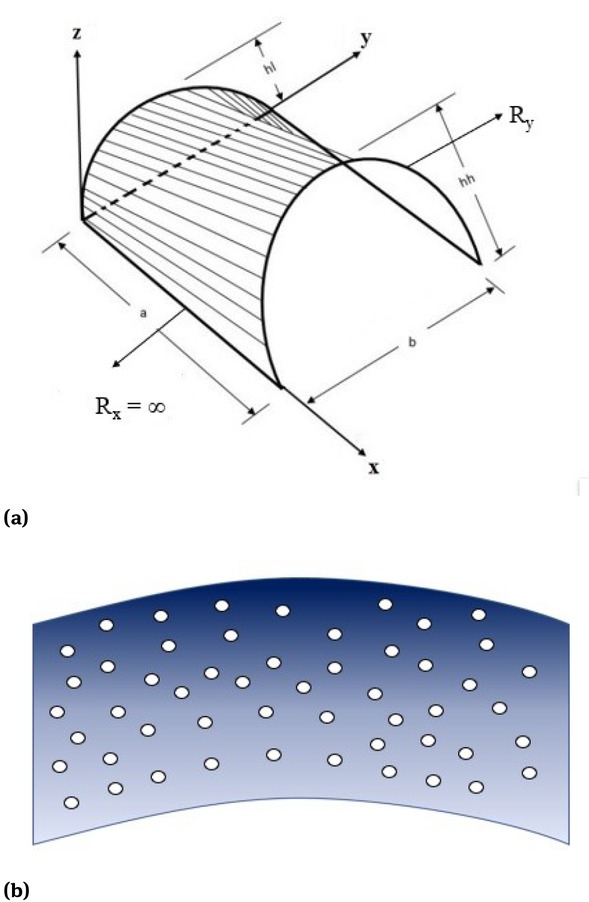
(a) Geometry of conoidal shell and (b) porosities models for even porosity in thickness coordinate
where,
where β (β << 1) is the volume fraction of porosities. P(z) implies material properties like the Young’s modulus of elasticity (E), material density (ρ) and Poisson’s ratio (ν) of the FGM porous conoidal shell.
Once the volume fraction index of material constituents is known, the Young’s modulus at any point ‘z’ can be calculated as per the rule of mixture.
where Ec, Vc and Em, Vm are the material properties and volume fraction of ceramic and metal, respectively, and n is the volume-fraction index.
2.1 Theory and formulation
2.1.1 Displacement field and strains
In order to develope the mathematical model, the displacement fields for FGM shell are considered on the basis of the third order shell theory and are as follows:
where the middle section is taken as a reference for material coordinates (x, y, z). u, v, w denoted the displacements of along the (x, y, z) coordinates, u0, v0, w0 are corresponding displacements on the mid-plane. θx,θy are the bending rotations normal to the mid-plane about the y axis and x-axes, respectively. The functions ξx, ξy , ζx and ζy are higher order terms of Taylor’s series expansion at the midplane of the conoidal shell. By imposing the boundary condition (zero transverse shear strain at top and bottom) in Eq. (4), the function ξx, ξy , ζx and ζy will be calculated as
Replacing the unknown in Eq. (5) into Eq. (4), we obtain
For omitting C1 continuity problem associated with TSDT, the out of plane derivatives are replaced by the following relations
The final form of displacement filed expression owning C0 continuity is written as
Hence, the field variables per node taken in the present investigation are u0, v0, w0, θx, θy, Ψ x and Ψ y. Mathematically, it may be expressed as
where {δ} is termed as a displacement vector.
The strain vector may be expressed as
Further, the strain vector {ε} can be associated with global displacement vector {X} by the subsequent relationship
Here strain-displacement matrix [B] contains the derivatives of shape functions.
The in-plane and transverse shear strains are
The strain relationship can be written as:
where
2.1.2 Constitutive relationship
The linear stress-strain constitutive relationship for the FGM conoids are
where the constitutive matrix
where the term Qij can be obtained with the help of the Young’s modulus (E) and Poisson’s ratio (ν), in which E is the function of thickness coordinate.
3 Finite element modelling
3.1 Introduction
For the present 5C0 finite element (FE) model, nine noded isoparametric Lagrangian element with seven degrees of freedom at each node is utilized in the present investigation. The shape function (interpolation function) is used to express the generalized displacement vector and element geometry at any point within an element as
The shape functions Ni of nine noded isoprametric Lagrangian element are depicted below.
For corner nodes:
For mid nodes:
For centre node:
3.2 Governing equation
The strain energy may be expressed as
By using the Eq. (15), the above expression can be represented as
where, [D] = ∫ [H]T [Q] [H] dx3 in which [H] is the matrix that contains the terms involving z and h.
By utilizing Eq. (11) the stiffness matrix [K] is written as
4 Results and discussion
In this section, the bending analysis of FGM porous conoidal shells was analysed under various type of mechanical loading. Parameters like thickness ratio, aspect ratio, hl/hh ratio, porosities and volume fraction index are also accomplished for numerical results. Unless stated otherwise, the following non-dimensional factors are utilized in the upcoming examples.
Non-dimensional quantities used are
The loading patterns used in the present analysis are written below:
The details of some of the boundary condition (BC) used are as follows:
Simply supported (SSSS):
At x = 0, a v = w = θy = ψ y = 0
At y = 0, b u = w = θx = ψ x = 0
Clamped (CCCC):
At x = 0, a and y = 0, b u = v = w = θx = θy = ψ x = ψ y = 0
Clamped and simply supported (CCSS):
At x = 0, a u = v = w = θx = θy = ψ x = ψ y = 0
At y = 0, b u = w = θx = ψ x = 0
4.1 Comparison and convergence study
Three appropriate examples have been solved to check the consistency and the stability of present FE results. No results for FGM porous conoidal shellwere found in the literature; hence, the effectiveness of the present formulation has been tested by relating dimensionless deflection for FGM porous plate and isotropic conoidal shell. The material properties of the FGM components used in the present study are as follows:
FGM-1 (Al/ZrO2): Ec = 151 GPa, Em = 70 GPa, νc = νm = 0.3,
ρc = 3000 kg/m3, ρm = 2707 kg/m3
FGM-2 (Al/Al2O3): Ec = 380GPa, Em = 70 GPa, νc = νm = 0.3,
ρc = 3800 kg/m3, ρm = 2707 kg/m3
Example 1. The convergence study of the dimensionless maximum deflection of FGM-1 (Al/ZrO2) plate was conducted for four power law indices (n = 0, 0.5, 1,∞) and presented in Table 1. For this particular example, we used hl = 0 and hh = 0 in the present FE code of the FGM-1 conoidal shell for converting it into FGM plate. It was found that at 16 × 16 mesh size, the results converge for the present nine noded isoparametric elements. From Table 1, it was noted that our numerical results are consistent with Ferreira et al. [31].
Comparison of non-dimensional maximum deflection at the centroid of simply supported FGM plate.
| Volume fraction index | ||||
|---|---|---|---|---|
| Mesh | Ceramic | 0.5 | 1 | Metal |
| 6x6 | 0.02480 | 0.03329 | 0.03680 | 0.05350 |
| 8x8 | 0.02481 | 0.03331 | 0.03685 | 0.05352 |
| 12x12 | 0.02482 | 0.03333 | 0.03688 | 0.05353 |
| 16x16 | 0.02482 | 0.03333 | 0.03688 | 0.05353 |
| Ferreira et al. [31] | 0.0248 | 0.0330 | 0.0368 | 0.0536 |
Example 2. Fig. 2 represents the comparison of dimensionless maximum transverse displacement of simply supported FGM porous plate. The bottom layer of FGM plate is metallic and the top layer is ceramic. For various value of volume fraction indices, the results were compared with Akbaş [24] and again it showed a decent agreement.
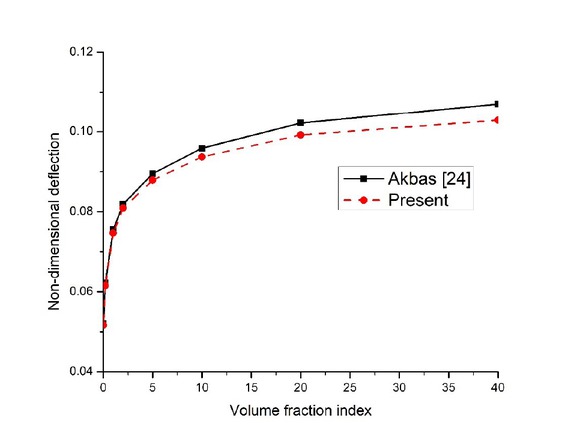
Comparison of non-dimensional deflection of FGM-1 porous plate subjected to uniform loading.
Comparison of deflection (x10−2) of simply supported isotropic conoid under uniformly distributed load along y/b = 0.5.
| x1/a | Bakshi and Chakravorty [22] | Hadid [17] | Present |
|---|---|---|---|
| 0.10 | 2.3680 | 2.5231 | 2.5621 |
| 0.40 | 5.1557 | 4.6333 | 4.7609 |
| 0.60 | 4.0510 | 3.5448 | 3.8575 |
| 0.70 | 3.4129 | 3.3149 | 3.2970 |
| 0.80 | 2.4809 | 2.5544 | 2.5949 |
Example 3. No results for FGM porous conoidal shell were available in literature; thus, the presented FE result of FGM porous conoidal shell were compared with numerical result of isotropic conoidal shell. The Poisson’s ratio ν = 0.15, hl/hh = 0.5 and side-to-thickness ratio a/h = 19 was used to validate present result. Table 4 shows the validation of present FE formulation with Hadid [17] and Bakshi and Chakravorty [22]. The validation study confirms the improvement of the present FE result over Bakshi and Chakravorty [22] as the current results are closer to the elasticity results presented by Hadid [17].
Variation of non-dimensional deflection of FGM porous conoidal shell subjected to uniform loading.
| n | β | Boundary condition | |||||
|---|---|---|---|---|---|---|---|
| SSSS | CCCC | CCSS | CSCS | CCFF | CFCF | ||
| 0 | 0 | 1.2981 | 0.8857 | 1.0019 | 1.0207 | 2.6063 | 29.1371 |
| (0.40,0.50) | (0.45,0.50) | (0.45,0.50) | (0.50,0.55) | (0.475,0.0) | (1,1) | ||
| 0.1 | 1.4218 | 0.9684 | 1.0953 | 1.1168 | 2.7953 | 31.2321 | |
| (0.40,0.50) | (0.45,0.50) | (0.45,0.50) | (0.50,0.55) | (0.475,0.0) | (1,1) | ||
| 0.2 | 1.5642 | 1.0636 | 1.2028 | 1.2274 | 3.0146 | 33.6526 | |
| (0.40,0.50) | (0.45,0.50) | (0.45,0.50) | (0.50,0.55) | (0.475,0.0) | (1,1) | ||
| 0.2 | 0 | 1.4206 | 1.0183 | 1.1185 | 1.1451 | 3.0296 | 34.3131 |
| (0.40,0.50) | (0.45,0.50) | (0.45,0.50) | (0.475,0.55) | (0.475,0.0) | (1,1) | ||
| 0.1 | 1.5705 | 1.1279 | 1.2353 | 1.2666 | 3.2943 | 37.3592 | |
| (0.40,0.50) | (0.45,0.50) | (0.45,0.50) | (0.475,0.55) | (0.475,0.0) | (1,1) | ||
| 0.2 | 1.7460 | 1.2575 | 1.3726 | 1.4095 | 3.6126 | 40.9732 | |
| (0.40,0.50) | (0.45,0.50) | (0.45,0.50) | (0.475,0.55) | (0.475,0.0) | (1,1) | ||
| 0.5 | 0 | 1.5310 | 1.1232 | 1.2174 | 1.2500 | 3.3433 | 37.9973 |
| (0.40,0.50) | (0.45,0.50) | (0.45,0.50) | (0.475,0.55) | (0.475,0.0) | (1,1) | ||
| 0.1 | 1.7064 | 1.2574 | 1.3567 | 1.3957 | 3.6762 | 41.8726 | |
| (0.40,0.50) | (0.45,0.50) | (0.45,0.50) | (0.475,0.55) | (0.475,0.0) | (1,1) | ||
| 0.2 | 1.9164 | 1.4203 | 1.5244 | 1.5714 | 4.0885 | 46.6175 | |
| (0.40,0.50) | (0.45,0.50) | (0.45,0.50) | (0.475,0.55) | (0.475,0.0) | (1,1) | ||
| 1 | 0 | 1.6678 | 1.2446 | 1.3365 | 1.3755 | 3.6943 | 42.0038 |
| (0.40,0.50) | (0.45,0.50) | (0.45,0.50) | (0.475,0.55) | (0.475,0.0) | (1,1) | ||
| 0.1 | 1.8781 | 1.4110 | 1.5062 | 1.5537 | 4.1158 | 46.9387 | |
| (0.40,0.50) | (0.45,0.50) | (0.45,0.50) | (0.475,0.55) | (0.475,0.0) | (1,1) | ||
| 0.2 | 2.1368 | 1.6200 | 1.7167 | 1.7751 | 4.6570 | 53.2180 | |
| (0.40,0.50) | (0.45,0.50) | (0.45,0.50) | (0.475,0.55) | (0.475,0.0) | (1,1) | ||
| 10 | 0 | 2.2517 | 1.6142 | 1.7756 | 1.8275 | 4.6538 | 51.6012 |
| (0.40,0.50) | (0.475,0.50) | (0.45,0.50) | (0.50,0.55) | (0.475,0.0) | (1,1) | ||
| 0.1 | 2.6280 | 1.8928 | 2.0725 | 2.1391 | 5.3401 | 59.2021 | |
| (0.40,0.50) | (0.475,0.50) | (0.45,0.50) | (0.50,0.55) | (0.475,0.0) | (1,1) | ||
| 0.2 | 3.1314 | 2.2722 | 2.4727 | 2.5604 | 6.2851 | 69.5130 | |
| (0.40,0.50) | (0.475,0.50) | (0.45,0.50) | (0.50,0.55) | (0.475,0.0) | (1,1) | ||
| ∞ | 0 | 2.8002 | 1.9107 | 2.1613 | 2.2018 | 5.6221 | 62.8531 |
| (0.40,0.50) | (0.45,0.50) | (0.45,0.50) | (0.50,0.55) | (0.475,0.0) | (1,1) | ||
| 0.1 | 3.3867 | 2.3082 | 2.6092 | 2.6602 | 6.6763 | 75.0419 | |
| (0.40,0.50) | (0.45,0.50) | (0.45,0.50) | (0.50,0.55) | (0.475,0.0) | (1,1) | ||
| 0.2 | 4.2094 | 2.8622 | 3.2367 | 3.3030 | 8.1124 | 90.5591 | |
| (0.40,0.50) | (0.45,0.50) | (0.45,0.50) | (0.50,0.55) | (0.475,0.0) | (1,1) | ||
Variation of non-dimensional deflection of FGM porous conoidal shell subjected to sin-sin loading.
| n | β | Boundary condition | |||||
|---|---|---|---|---|---|---|---|
| SSSS | CCCC | CCSS | CSCS | CCFF | CFCF | ||
| 0 | 0 | 0.8803 | 0.6628 | 0.7251 | 0.7328 | 1.3424 | 9.8687 |
| (0.425,0.50) | (0.475,0.50) | (0.475,0.50) | (0.50,0.525) | (0.475,0.50) | (1,1) | ||
| 0.1 | 0.9635 | 0.7244 | 0.7924 | 0.8014 | 1.4602 | 10.5537 | |
| (0.425,0.50) | (0.475,0.50) | (0.475,0.50) | (0.50,0.525) | (0.475,0.50) | (1,1) | ||
| 0.2 | 1.0593 | 0.7954 | 0.8698 | 0.8803 | 1.5961 | 11.3454 | |
| (0.425,0.50) | (0.475,0.50) | (0.475,0.50) | (0.50,0.525) | (0.475,0.50) | (1,1) | ||
| 0.2 | 0 | ||||||
| 0.9732 | 0.7631 | 0.8160 | 0.8290 | 1.5527 | 11.5935 | ||
| (0.425,0.50) | (0.475,0.50) | (0.475,0.50) | (0.50,0.525) | (0.475,0.50) | (1,1) | ||
| 0.1 | 1.0760 | 0.8451 | 0.9016 | 0.9171 | 1.7120 | 12.5893 | |
| (0.425,0.50) | (0.475,0.50) | (0.475,0.50) | (0.50,0.525) | (0.475,0.50) | (1,1) | ||
| 0.2 | 1.1967 | 0.9421 | 1.0025 | 1.0211 | 1.9008 | 13.7711 | |
| (0.425,0.50) | (0.475,0.50) | (0.475,0.50) | (0.50,0.525) | (0.475,0.50) | (1,1) | ||
| 0.5 | 0 | 1.0543 | 0.8419 | 0.8913 | 0.9081 | 1.7127 | 12.8317 |
| (0.425,0.50) | (0.475,0.50) | (0.475,0.50) | (0.50,0.525) | (0.475,0.50) | (1,1) | ||
| 0.1 | 1.1761 | 0.9424 | 0.9943 | 1.0147 | 1.9092 | 14.1007 | |
| (0.425,0.50) | (0.475,0.50) | (0.475,0.50) | (0.50,0.525) | (0.475,0.50) | (1,1) | ||
| 0.2 | 1.3225 | 1.0646 | 1.1187 | 1.1437 | 2.1486 | 15.6543 | |
| (0.425,0.50) | (0.475,0.50) | (0.475,0.50) | (0.475,0.525) | (0.475,0.50) | (1,1) | ||
| 1 | 0 | 1.1532 | 0.9328 | 0.9808 | 1.0016 | 1.8943 | 14.1854 |
| (0.425,0.50) | (0.475,0.50) | (0.475,0.50) | (0.50,0.525) | (0.475,0.50) | (1,1) | ||
| 0.1 | 1.3006 | 1.0575 | 1.1070 | 1.1328 | 2.1392 | 15.8053 | |
| (0.425,0.50) | (0.475,0.50) | (0.475,0.50) | (0.50,0.525) | (0.475,0.50) | (1,1) | ||
| 0.2 | 1.4831 | 1.2143 | 1.2644 | 1.2966 | 2.4482 | 17.8653 | |
| (0.425,0.50) | (0.475,0.50) | (0.475,0.50) | (0.475,0.525) | (0.475,0.50) | (1,1) | ||
| 10 | 0 | 1.5441 | 1.2057 | 1.2918 | 1.3185 | 2.4156 | 17.5095 |
| (0.45,0.50) | (0.475,0.50) | (0.475,0.50) | (0.50,0.525) | (0.475,0.50) | (1,1) | ||
| 0.1 | 1.8038 | 1.4131 | 1.5087 | 1.5437 | 2.8151 | 20.0428 | |
| (0.45,0.50) | (0.475,0.50) | (0.475,0.50) | (0.50,0.525) | (0.475,0.50) | (1,1) | ||
| 0.2 | 2.1529 | 1.6956 | 1.8019 | 1.8491 | 3.3587 | 23.4823 | |
| (0.45,0.50) | (0.475,0.50) | (0.475,0.50) | (0.50,0.525) | (0.475,0.50) | (1,1) | ||
| Metal | 0 | 1.8989 | 1.4297 | 1.5641 | 1.5808 | 2.8958 | 21.2883 |
| (0.425,0.50) | (0.475,0.50) | (0.475,0.50) | (0.50,0.525) | (0.475,0.50) | (1,1) | ||
| 0.1 | 2.2956 | 1.7270 | 1.8881 | 1.9096 | 3.4902 | 25.3677 | |
| (0.425,0.50) | (0.475,0.50) | (0.475,0.50) | (0.50,0.525) | (0.475,0.50) | (1,1) | ||
| 0.2 | 2.8506 | 2.1404 | 2.3407 | 2.3689 | 4.2952 | 30.5302 | |
| (0.425,0.50) | (0.475,0.50) | (0.475,0.50) | (0.50,0.525) | (0.475,0.50) | (1,1) | ||
4.2 Results and discussion
In order to analyze FGM conoidal shells under various type of transverse loading, different composition of material constituents, different combination of boundary condition, numerous value of volume fraction index, side-to-thickness ratio, aspect ratio and hl/hh ratio are considered.
Tables 3 and 4 represent the dimensionless maximum deflection and their location subjected to uniform and sin-sin loading for the FGM-1 porous conoidal shell, respectively.
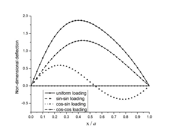
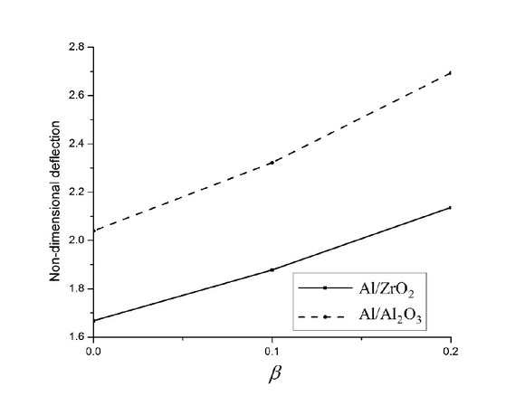
The numerical results were computed for a/h = 10, a/b = 1, hl/hh = 0.25 (hl = 0.05, hh = 0.2), and SSSS, CCCC, CCSS, CSCS, CCFF and CFCF boundary condition. It can be observed from that the maximum deflection of the conoidal shell occurs at a different location, unlike plate structure where maximum deflection occurs at the midpoint. These numerical values revealed that the dimensionless deflection of porous conoidal shell increases along with porosity percentage because of the decrease in the equivalent modulus of elasticity. Apart from that as we move from n = 0 to n = ∞, the dimensionless deflection of the porous conoidal shell is increased and it may be attributed to the higher volume fraction index which leads to lesser ceramic content, thus reducing its stiffness. Intrestingly, around 200% increase in the maximum dimensionless deflection was noticed as the volume fraction index changed from 0 to ∞ and almost 30% growths were displayed when the volume fraction index changed from 0 to 1 for all boundary conditions. Remarkably, CFCF boundary condition yields the highest deflection while CCCC retains the lowest deflection value among all considered boundary conditions. The influence of thickness ratio on dimensionless deflection of FGM-1 porous conoidal shell is tabulated in Tables 5 and 6 subjected to uniform and sin-sin loading, respectively. These numerical results highlighted that non-dimensional deflection increases along with the thickness of porous conoidal shell. The correlation between hl/hh ratio and dimensionless deflection of FGM-1 porous conoids subjected to uniform loading is tested in Table 7. Interestingly, for higher value of hl/hh ratio, lower value of dimensionless deflection is noticed. The decrease in hl/hh ratio reduces the curvature of the lower end (hl) of the conoidal shell, due to this the stiffness of shell reduces, therefore deflection increased. Fig. 3 depicts the variation of dimensionless deflection along the centre line subjected to uniform loading. The numerical results of dimensionless deflection of FGM-1 porous conoids subjected to various type of transverse load were plotted in Fig. 4. a/h = 10, a/b = 1 and hl/hh = 0.25 was used. The maximum and minimum non-dimensional deflections were found under uniform loading and cos-cos loading respectively. In Fig. 5, the maximum dimensionless deflection of FGM-1 and FGM-2 porous conoidal shellwas plotted against the porosity coefficient. With the rise in the porosity parameter, the transverse deflection of the porous conoidal shell increases for both types of FGM. The dimensionless value of stresses increases along with the thickness ratio of porous conoidal shell. Fig. 6 shows the dimensionless value of axial stress
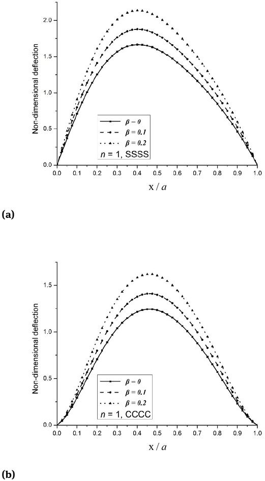
Variation of non-dimensional deflection of FGM-1 porous conoidal shell under uniform loading.
Variation of non-dimensional deflection of FGM-1 porous conoidal shell under uniform loading for β = 0.1.
Variation of non-dimensional deflection of FGM porous conoidal shell under uniform loading.
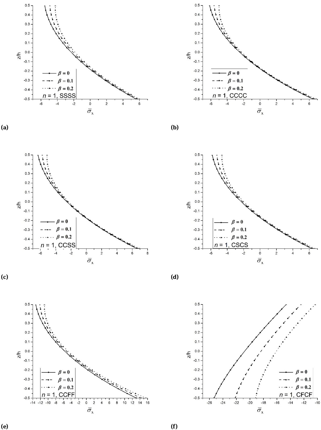
Effect of porosity on dimensionless axial stress of FGM-1 porous conoidal shell under uniform loading.
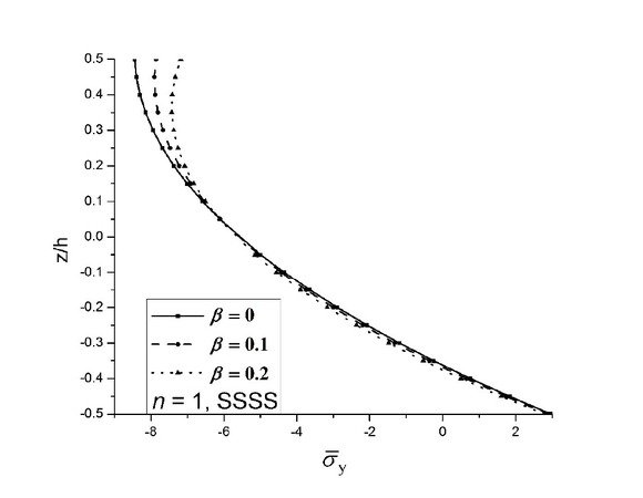
Effect of porosity on dimensionless axial stress of FGM-1 porous conoidal shell under uniform loading.
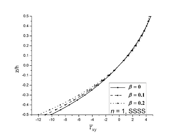
Effect of porosity on dimensionless shear stress of FGM-1 porous conoidal shell under uniform loading.
Variation of non-dimensional deflection of simply supported FGM porous conoidal shell subjected to uniform loading.
| n | β | a/h | ||||
|---|---|---|---|---|---|---|
| 5 | 10 | 20 | 50 | 100 | ||
| 0 | 0 | 2.9982 | 1.2981 | 0.4700 | 0.1128 | 0.0380 |
| (0.45,0.50) | (0.40,0.50) | (0.325,0.50) | (0.25,0.50) | (0.20,0.50) | ||
| 0.1 | 3.2770 | 1.4218 | 0.5148 | 0.1235 | 0.0416 | |
| (0.45,0.50) | (0.40,0.50) | (0.325,0.50) | (0.225,0.50) | (0.20,0.50) | ||
| 0.2 | 3.5978 | 1.5642 | 0.5663 | 0.1358 | 0.0457 | |
| (0.45,0.50) | (0.40,0.50) | (0.325,0.50) | (0.225,0.50) | (0.20,0.50) | ||
| 0.2 | 0 | 3.2837 | 1.4206 | 0.5222 | 0.1281 | 0.0435 |
| (0.45,0.50) | (0.40,0.50) | (0.325,0.50) | (0.25,0.50) | (0.20,0.50) | ||
| 0.1 | 3.6238 | 1.5705 | 0.5778 | 0.1419 | 0.0481 | |
| (0.45,0.50) | (0.40,0.50) | (0.325,0.50) | (0.25,0.50) | (0.20,0.50) | ||
| 0.2 | 4.0214 | 1.7460 | 0.6432 | 0.1583 | 0.0537 | |
| (0.45,0.50) | (0.40,0.50) | (0.325,0.50) | (0.225,0.50) | (0.20,0.50) | ||
| 0.5 | 0 | 3.5220 | 1.5310 | 0.5693 | 0.1416 | 0.0482 |
| (0.45,0.50) | (0.40,0.50) | (0.325,0.50) | (0.25,0.50) | (0.20,0.50) | ||
| 0.1 | 3.9169 | 1.7064 | 0.6358 | 0.1586 | 0.0539 | |
| (0.45,0.50) | (0.40,0.50) | (0.325,0.50) | (0.25,0.50) | (0.20,0.50) | ||
| 0.2 | 4.3882 | 1.9164 | 0.7161 | 0.1792 | 0.0610 | |
| (0.45,0.50) | (0.40,0.50) | (0.325,0.50) | (0.25,0.50) | (0.20,0.50) | ||
| 1 | 0 | 3.8154 | 1.6678 | 0.6269 | 0.1577 | 0.0538 |
| (0.45,0.50) | (0.40,0.50) | (0.325,0.50) | (0.25,0.50) | (0.20,0.50) | ||
| 0.1 | 4.2837 | 1.8781 | 0.7083 | 0.1790 | 0.0611 | |
| (0.45,0.50) | (0.40,0.50) | (0.325,0.50) | (0.25,0.50) | (0.20,0.50) | ||
| 0.2 | 4.8576 | 2.1368 | 0.8096 | 0.2057 | 0.0702 | |
| (0.45,0.50) | (0.40,0.50) | (0.325,0.50) | (0.25,0.50) | (0.20,0.50) | ||
| 10 | 0 | 5.1082 | 2.2517 | 0.8454 | 0.2108 | 0.0718 |
| (0.45,0.50) | (0.40,0.50) | (0.325,0.50) | (0.25,0.50) | (0.20,0.50) | ||
| 0.1 | 5.9353 | 2.6280 | 0.9913 | 0.2484 | 0.0847 | |
| (0.45,0.50) | (0.40,0.50) | (0.325,0.50) | (0.25,0.50) | (0.20,0.50) | ||
| 0.2 | 7.0362 | 3.1314 | 1.1890 | 0.3001 | 0.1025 | |
| (0.45,0.50) | (0.40,0.50) | (0.325,0.50) | (0.25,0.50) | (0.20,0.50) | ||
| Metal | 0 | 6.4675 | 2.8002 | 1.0139 | 0.2433 | 0.0820 |
| (0.45,0.50) | (0.40,0.50) | (0.325,0.50) | (0.25,0.50) | (0.20,0.50) | ||
| 0.1 | 7.8297 | 3.3867 | 1.2245 | 0.2934 | 0.0988 | |
| (0.45,0.50) | (0.40,0.50) | (0.325,0.50) | (0.25,0.50) | (0.20,0.50) | ||
| 0.2 | 9.6818 | 4.2094 | 1.5238 | 0.3654 | 0.1231 | |
| (0.45,0.50) | (0.40,0.50) | (0.325,0.50) | (0.225,0.50) | (0.20,0.50) | ||
Variation of non-dimensional deflection of simply supported FGM porous conoidal shell subjected to sin-sin loading.
| n | β | a/h | ||||
|---|---|---|---|---|---|---|
| 5 | 10 | 20 | 50 | 100 | ||
| 0 | 0 | 1.9914 | 0.8803 | 0.3355 | 0.0972 | 0.0419 |
| (0.475,0.50) | (0.425,0.50) | (0.325,0.50) | (0.25,0.50) | (0.20,0.50) | ||
| 0.1 | 2.1742 | 0.9635 | 0.3672 | 0.1064 | 0.0457 | |
| (0.475,0.50) | (0.425,0.50) | (0.325,0.50) | (0.225,0.50) | (0.20,0.50) | ||
| 0.2 | 2.3847 | 1.0593 | 0.4036 | 0.1169 | 0.0501 | |
| (0.475,0.50) | (0.425,0.50) | (0.325,0.50) | (0.225,0.50) | (0.20,0.50) | ||
| 0.2 | 0 | 2.1945 | 0.9732 | 0.3788 | 0.1132 | 0.0487 |
| (0.475,0.50) | (0.425,0.50) | (0.325,0.50) | (0.25,0.50) | (0.20,0.50) | ||
| 0.1 | 2.4203 | 1.0760 | 0.4193 | 0.1256 | 0.0539 | |
| (0.475,0.50) | (0.425,0.50) | (0.325,0.50) | (0.25,0.50) | (0.20,0.50) | ||
| 0.2 | 2.6848 | 1.1967 | 0.4672 | 0.1403 | 0.0601 | |
| (0.475,0.50) | (0.425,0.50) | (0.325,0.50) | (0.25,0.50) | (0.20,0.50) | ||
| 0.5 | 0 | 2.3630 | 1.0543 | 0.4162 | 0.1262 | 0.0544 |
| (0.475,0.50) | (0.425,0.50) | (0.325,0.50) | (0.25,0.50) | (0.20,0.50) | ||
| 0.1 | 2.6274 | 1.1761 | 0.4655 | 0.1417 | 0.0609 | |
| (0.475,0.50) | (0.425,0.50) | (0.325,0.50) | (0.25,0.50) | (0.20,0.50) | ||
| 0.2 | 2.9441 | 1.3225 | 0.5254 | 0.1607 | 0.0688 | |
| (0.475,0.50) | (0.425,0.50) | (0.325,0.50) | (0.25,0.50) | (0.20,0.50) | ||
| 1 | 0 | 2.5690 | 1.1532 | 0.4609 | 0.1411 | 0.0609 |
| (0.475,0.50) | (0.425,0.50) | (0.325,0.50) | (0.25,0.50) | (0.20,0.50) | ||
| 0.1 | 2.8853 | 1.3006 | 0.5221 | 0.1608 | 0.0691 | |
| (0.475,0.50) | (0.425,0.50) | (0.325,0.50) | (0.25,0.50) | (0.20,0.50) | ||
| 0.2 | 3.2749 | 1.4831 | 0.5988 | 0.1857 | 0.0796 | |
| (0.475,0.50) | (0.425,0.50) | (0.325,0.50) | (0.25,0.50) | (0.20,0.50) | ||
| 10 | 0 | 3.4313 | 1.5441 | 0.6121 | 0.1825 | 0.0790 |
| (0.475,0.50) | (0.45,0.50) | (0.325,0.50) | (0.25,0.50) | (0.20,0.50) | ||
| 0.1 | 3.9887 | 1.8038 | 0.7187 | 0.2151 | 0.0930 | |
| (0.475,0.50) | (0.45,0.50) | (0.325,0.50) | (0.25,0.50) | (0.20,0.50) | ||
| 0.2 | 4.7342 | 2.1529 | 0.8638 | 0.2600 | 0.1123 | |
| (0.475,0.50) | (0.45,0.50) | (0.325,0.50) | (0.25,0.50) | (0.20,0.50) | ||
| Metal | 0 | 4.2957 | 1.8989 | 0.7238 | 0.2098 | 0.0903 |
| (0.475,0.50) | (0.425,0.50) | (0.325,0.50) | (0.25,0.50) | (0.20,0.50) | ||
| 0.1 | 5.1968 | 2.2956 | 0.8735 | 0.2531 | 0.1089 | |
| (0.475,0.50) | (0.425,0.50) | (0.325,0.50) | (0.225,0.50) | (0.20,0.50) | ||
| 0.2 | 6.4171 | 2.8506 | 1.0862 | 0.3147 | 0.1349 | |
| (0.475,0.50) | (0.425,0.50) | (0.325,0.50) | (0.225,0.50) | (0.20,0.50) | ||
Variation of non-dimensional deflection of simply supported FGM porous conoidal shell subjected to uniform loading (a/h = 10).
| hl/hh | β | n | ||||||
|---|---|---|---|---|---|---|---|---|
| Ceramic | 0.2 | 0.5 | 1 | 10 | Metal | |||
| 0.25 | 0 | 1.2981 | 1.4206 | 1.531 | 1.6678 | 2.2517 | 2.8002 | |
| (0.40,0.50) | (0.40,0.50) | (0.40,0.50) | (0.40,0.50) | (0.40,0.50) | (0.40,0.50) | |||
| 0.1 | 1.4218 | 1.5705 | 1.7064 | 1.8781 | 2.628 | 3.3867 | ||
| (0.40,0.50) | (0.40,0.50) | (0.40,0.50) | (0.40,0.50) | (0.40,0.50) | (0.40,0.50) | |||
| 0.2 | 1.5642 | 1.746 | 1.9164 | 2.1368 | 3.1314 | 4.2094 | ||
| (0.40,0.50) | (0.40,0.50) | (0.40,0.50) | (0.40,0.50) | (0.40,0.50) | (0.40,0.50) | |||
| 0.20 | 0 | 1.3756 | 1.5060 | 1.6220 | 1.7654 | 2.3783 | 2.9674 | |
| (0.40,0.50) | (0.40,0.50) | (0.40,0.50) | (0.40,0.50) | (0.40,0.50) | (0.40,0.50) | |||
| 0.1 | 1.5066 | 1.6648 | 1.8077 | 1.9877 | 2.7744 | 3.5895 | ||
| (0.40,0.50) | (0.40,0.50) | (0.40,0.50) | (0.40,0.50) | (0.40,0.50) | (0.40,0.50) | |||
| 0.2 | 1.6574 | 1.8507 | 2.0301 | 2.2613 | 3.3036 | 4.4601 | ||
| (0.40,0.50) | (0.40,0.50) | (0.40,0.50) | (0.40,0.50) | (0.40,0.50) | (0.40,0.50) | |||
| 0.15 | 0 | 1.4563 | 1.5951 | 1.7171 | 1.8674 | 2.5100 | 3.1416 | |
| (0.40,0.50) | (0.40,0.50) | (0.40,0.50) | (0.40,0.50) | (0.40,0.50) | (0.40,0.50) | |||
| 0.1 | 1.5949 | 1.7633 | 1.9137 | 2.1024 | 2.9266 | 3.8006 | ||
| (0.40,0.50) | (0.40,0.50) | (0.40,0.50) | (0.40,0.50) | (0.40,0.50) | (0.40,0.50) | |||
| 0.2 | 1.7543 | 1.9602 | 2.1489 | 2.3915 | 3.4827 | 4.7209 | ||
| (0.40,0.50) | (0.40,0.50) | (0.40,0.50) | (0.40,0.50) | (0.40,0.50) | (0.40,0.50) | |||
| 0.10 | 0 | 1.5398 | 1.6877 | 1.8160 | 1.9735 | 2.6461 | 3.3215 | |
| (0.40,0.50) | (0.40,0.50) | (0.40,0.50) | (0.40,0.50) | (0.40,0.50) | (0.40,0.50) | |||
| 0.1 | 1.6861 | 1.8655 | 2.0238 | 2.2216 | 3.0839 | 4.0189 | ||
| (0.40,0.50) | (0.40,0.50) | (0.40,0.50) | (0.40,0.50) | (0.40,0.50) | (0.40,0.50) | |||
| 0.2 | 1.8544 | 2.0738 | 2.2725 | 2.5268 | 3.6676 | 4.9902 | ||
| (0.40,0.50) | (0.40,0.50) | (0.40,0.50) | (0.40,0.50) | (0.40,0.50) | (0.40,0.50) | |||
| 0.05 | 0 | 1.6253 | 1.7829 | 1.9179 | 2.0830 | 2.7858 | 3.5059 | |
| (0.40,0.50) | (0.40,0.50) | (0.40,0.50) | (0.40,0.50) | (0.40,0.50) | (0.40,0.50) | |||
| 0.1 | 1.7794 | 1.9707 | 2.1373 | 2.3446 | 3.2451 | 4.2425 | ||
| (0.40,0.50) | (0.40,0.50) | (0.40,0.50) | (0.40,0.50) | (0.40,0.50) | (0.40,0.50) | |||
| 0.2 | 1.9568 | 2.1907 | 2.3998 | 2.6665 | 3.8572 | 5.2658 | ||
| (0.40,0.50) | (0.40,0.50) | (0.40,0.50) | (0.40,0.50) | (0.40,0.50) | (0.40,0.50) | |||
| 0.00 | 0 | 1.7119 | 1.8800 | 2.0221 | 2.1949 | 2.9278 | 3.6928 | |
| (0.40,0.50) | (0.40,0.50) | (0.40,0.50) | (0.40,0.50) | (0.40,0.50) | (0.40,0.50) | |||
| 0.1 | 1.8740 | 2.0779 | 2.2533 | 2.4704 | 3.4091 | 4.4690 | ||
| (0.40,0.50) | (0.40,0.50) | (0.40,0.50) | (0.40,0.50) | (0.40,0.50) | (0.40,0.50) | |||
| 0.2 | 2.0605 | 2.3098 | 2.5300 | 2.8094 | 4.0499 | 5.5448 | ||
| (0.40,0.50) | (0.40,0.50) | (0.40,0.50) | (0.40,0.50) | (0.40,0.50) | (0.40,0.50) | |||
5 Conclusion
This paper focuses on the influence of porosity on the bending analysis of FGM porous conoidal shell based on TSDT subjected to the various types of loads using an efficient C0 FE model. The subsequent outcomes of the present study were written below for the volume fraction indices, skew angles, thickness ratios, hl/hh ratios and various types of end support.
The presence of porosity increases the deflection in comparison with perfect conoidal shell.
The dimensionless deflection of the FGM porous conoidal shell increases along with the porosity volume fraction and volume fraction index.
The porosity shows an insignificant effect on the dimensionless stresses of FGM porous conoidal shell except CFCF boundary condition.
The non-dimensional deflection and dimensionless stresses increase with increase in thickness of shell.
The dimensionless deflection and normal stresses at the top of the rhombic shell increase with a reduction in the hl/hh ratio subjected to uniform and sin-sin loading.
References
[1] Koizumi M. Compos. Part B 1997, 28B, 1–4.10.1016/S1359-8368(96)00016-9Search in Google Scholar
[2] Eslami MR, Babaei MH, Poultangari R. Int. J. Press. Vessel. Pip. 2005, 82, 522–527.10.1016/j.ijpvp.2005.01.002Search in Google Scholar
[3] Zhao X, Lee YYÃ, Liew KM. Int. J. Mech. Sci. 2009, 51, 694–707.10.1016/j.ijmecsci.2009.08.001Search in Google Scholar
[4] Kashtalyan M, Menshykova M. Compos. Struct. 2009, 87, 36–43.10.1016/j.compstruct.2007.12.003Search in Google Scholar
[5] Ameur M, Tounsi A, Mechab I, El Bedia AA. KSCE J. Civ. Eng. 2011, 15, 1405-1414.10.1007/s12205-011-1361-zSearch in Google Scholar
[6] Natarajan S, Manickam G. Finite Elem. Anal. Des. 2012, 57, 32–42.10.1016/j.finel.2012.03.006Search in Google Scholar
[7] Kumar A, Chakrabarti A, Ketkar M. Lat. Am. j. solids struct. 2013, 10, 891-919.10.1590/S1679-78252013000600002Search in Google Scholar
[8] Bessaim A, Houari MS, Tounsi A, Mahmoud S, Bedia EAA. J. Sandw. Struct. Mater. 2013, 15, 671–703.10.1177/1099636213498888Search in Google Scholar
[9] Tornabene F, Viola E. Meccanica 2013, 48, 901–930.10.1007/s11012-012-9643-1Search in Google Scholar
[10] Sayyad AS, Ghugal YM. Int. J. Mech. Mater. Des. 2014, 10, 247–267.10.1007/s10999-014-9244-3Search in Google Scholar
[11] Viola E, Rossetti L, Fantuzzi N, Tornabene F. Compos. Struct. 2014, 112, 44–65.10.1016/j.compstruct.2014.01.039Search in Google Scholar
[12] Asemi K, Salehi M, Akhlaghi M. Int. J. Press. Vessel Pip. 2014, 119, 52–61.10.1016/j.ijpvp.2014.03.002Search in Google Scholar
[13] Dai H, Dai T. Meccanica 2014, 49, 1069–1081.10.1007/s11012-013-9853-1Search in Google Scholar
[14] Xiang S, Liu Y-Q. J. Sandw. Struct. Mater. 2016, 18, 579–596.10.1177/1099636216647928Search in Google Scholar
[15] Parihar RS, Setti SG, Sahu RK. Sci. Eng. Compos. Mater. 2016, 25, 309–336.10.1515/secm-2015-0395Search in Google Scholar
[16] Alipour MM, Shariyat M. Int. J. Mech. Mater. Des. 2017, 13, 125–157.10.1007/s10999-015-9321-2Search in Google Scholar
[17] Hadid HA. PhD Dissertation, University of Southampton, 1964.Search in Google Scholar
[18] Das AK, Bandyopadhyay JN. Comput. Struct. 1993, 49, 531–536.10.1016/0045-7949(93)90054-HSearch in Google Scholar
[19] Ghosh B, Bandyopadhyay JN. Comput. Struct. 1994, 53, 9–18.10.1016/0045-7949(94)90124-4Search in Google Scholar
[20] Das HS, Chakravorty D. Adv. Vib. Eng. 2009, 8, 321–328.Search in Google Scholar
[21] Kumari S, Chakravorty D. Int. J. Eng. Sci. Technol. 2010, 2, 54–70.10.4314/ijest.v2i4.59199Search in Google Scholar
[22] Bakshi K, Chakravorty D. Thin-Walled Struct. 2014, 76, 1–7.10.1016/j.tws.2013.10.021Search in Google Scholar
[23] Malekzadeh Fard K, Baghestani AM. Aerosp. Sci. Technol. 2017, 69, 136–48.10.1016/j.ast.2017.06.021Search in Google Scholar
[24] Akbaş ŞD. J. Appl. Comput. Mech. 2017, 3, 199–207.Search in Google Scholar
[25] Al Rjoub YS, Hamad AG. KSCE J. Civ. Eng. 2017, 21, 792–806.10.1007/s12205-016-0149-6Search in Google Scholar
[26] Eltaher MA, Fouda N, El-midany T, Sadoun AM. J. Brazilian Soc. Mech. Sci. Eng. 2018, 40, 141.10.1007/s40430-018-1065-0Search in Google Scholar
[27] Kiran MC, Kattimani SC, Vinyas M. Compos. Struct. 2018, 191, 36–77.10.1016/j.compstruct.2018.02.023Search in Google Scholar
[28] Gupta A, Talha M. Int. J. Struct. Stab. Dy. 2018, 18. doi:10.1142/S021945541850013X.10.1142/S021945541850013XSearch in Google Scholar
[29] Gupta A, Talha M. Int. J. Mech. Mater. Des. 2017, 14. doi:10.1007/s10999-017-9369-2.10.1007/s10999-017-9369-2Search in Google Scholar
[30] Gupta A, Talha M. Arab. J. Sci. Eng. 2018, 43, 4931. doi:10.1007/s13369-018-3240-0.10.1007/s13369-018-3240-0Search in Google Scholar
[31] Ferreira AJM, Roque CMC, Jorge RMN, Fasshauer GE, Batra RC. Mech. Adv. Mater. Struct. 2007, 14, 577–87.10.1080/15376490701672732Search in Google Scholar
© 2019 Md Irfan Ansari et al., published by De Gruyter
This work is licensed under the Creative Commons Attribution 4.0 Public License.
Articles in the same Issue
- Analysis on the impact response of fiber-reinforced composite laminates: an emphasis on the FEM simulation
- Artificial neural network for predicting the flexural bond strength of FRP bars in concrete
- Cyclic behavior of GFRP strengthened infilled RC frames with low and normal strength concrete
- Durability of basalt fiber-reinforced polymer bars in wet-dry cycles alkali-salt corrosion
- Effect of B4C particle size on the mechanical properties of B4C reinforced aluminum matrix layered composite
- Enhanced dielectric properties of BaTiO3 ceramics with cerium doping, manganese doping and Ce-Mn co-doping
- Free and forced vibration analysis of rectangular/circular/annular plates made of carbon fiber-carbon nanotube-polymer hybrid composites
- Influence of nano-SiO2 on the bonding strength and wear resistance properties of polyurethane coating
- Investigation of wear behavior of nanoalumina and marble dust-reinforced dental composites
- Negative effect of clay fillers on the polyvinyl alcohol biodegradation: technical note
- Photocatalytic activity of Cu2O/ZnO nanocomposite for the decomposition of methyl orange under visible light irradiation
- Sub-surface mechanical properties and sub-surface creep behavior of wood-plastic composites reinforced by organoclay
- Surface integrity in wire-EDM tangential turning of in situ hybrid metal matrix composite A359/B4C/Al2O3
- The influence of the WC-Co composite microstructure model on stress field heterogeneity at the microstructure level: FEM based study
- Vibration-damping characterization of the basalt/epoxy composite laminates containing graphene nanopellets
- A review on nanocomposite hydrogels and their biomedical applications
- Optimization and simulation analysis of structure parameters of OPCM ultrasonic longitudinal wave actuating element
- Research Article
- Preparation of POSS-triol/wollastonite composite particles by Liquid phase mechanochemical method and its application in UV curable coatings
- Research on preload relaxation for composite pre-tightened tooth connections
- Dough moulding compound reinforced silicone rubber insulating composites using polymerized styrene butadiene rubber as a compatibilizer
- Hydration And Microstructure Of Astm Type I Cement Paste
- Effects of NiO content on the microstructure and mechanical properties of AgSnO2NiO composites
- Overall buckling behaviour of laminated CFRP tubes with off-axis ply orientation in axial compression
- UV sensing optode for composite materials environment monitoring
- On crushing characteristics of hybrid sandwich aluminum-cardboard panels reinforced with glass fiber composite rods
- Preparation and characterization of Ni-Cu composite nanoparticles for conductive paints
- A research on the preparation of oil-adsorbing hydrophobic porous resins by high internal phase emulsions (HIPEs) template
- Material characteristics of random glass-mat-reinforced thermoplastic under cryogenic thermal cycles
- Differentiation of non-black fillers in rubber composites using linear discriminant analysis of principal components
- Research Article
- Efficiency of TiO2 catalyst supported by modified waste fly ash during photodegradation of RR45 dye
- Synthesis and performance of polyurethane/silicon oxide nano-composite coatings
- Study on preparation of magnesium-rich composite coating and performance enhancement by graft modification of epoxy resin
- Research Article
- Mechanical and wear properties of polyetheretherketone composites filled with basalt fibres
- Mechanical Properties of Al 25 wt.% Cu Functionally Graded Material
- Research Article
- Weight reduction of a carbon fibre composite wheel
- Synthesis, electrical properties, and kinetic thermal analysis of polyaniline/ polyvinyl alcohol - magnetite nanocomposites film
- Seismic Behaviour of TRC-Strengthened RC Columns under Different Constraint Conditions
- Characterization of neat and modified asphalt binders and mixtures in relation to permanent deformation
- Microstructures, interface structure and room temperature tensile properties of magnesium materials reinforced by high content submicron SiCp
- Research Article
- Effect of Cutting Temperature on Bending Properties of Carbon Fibre Reinforced Plastics
- Mechanical and tribological properties of B-C-N coatings sliding against different wood balls
- Thermal conductivity of unidirectional composites consisting of randomly dispersed glass fibers and temperature-dependent polyethylene matrix
- Effects of Waste Eggshells addition on Microstructures, Mechanical and Tribological Properties of Green Metal Matrix Composite
- Investigation of porosity effect on flexural analysis of doubly curved FGM conoids
- Review Article
- Utilization of tailings in cement and concrete: A review
- Research Article
- Equivalent stiffness prediction and global buckling analysis using refined analytical model of composite laminated box beam
- Mechanochemical synthesis of zincite doped with cadmium in various amounts
- Size-dependent vibration analysis of graphene-PMMA lamina based on non-classical continuum theory
- Automated, Quality Assured and High Volume Oriented Production of Fiber Metal Laminates (FML) for the Next Generation of Passenger Aircraft Fuselage Shells
- Research Article
- An investigation of the stitching effect on single lap shear joints in laminated composites
- The low-velocity impact and compression after impact (CAI) behavior of foam core sandwich panels with shape memory alloy hybrid face-sheets
- Effect of granulometric distribution on electromagnetic shielding effectiveness for polymeric composite based on natural graphite
- The enhancement of filament winding in marine launching rubber gasbag
- Research on ELID Grinding Mechanism and Process Parameter Optimization of Aluminum-Based Diamond Composites for Electronic Packaging