Structure-property-processing investigation of electrically conductive polypropylene nanocomposites
-
Radwan Dweiri
 ,
Hendra Suherman
,
Hendra Suherman

Abstract
This paper investigates the structure-property-processing correlations of electrically conductive polypropylene (PP) nanocomposites. The process parameters and fabrication techniques of PP-based composite materials were studied. Various structures of carbon allotrope-based materials, including synthetic graphite (SG), exfoliated graphene nanoplatelets (xGnP), multi-walled carbon nanotubes (MWCNTs) and carbon black (CB), were used to fabricate the PP-based nanocomposites. The nanocomposites were prepared by either direct melt mixing using an internal mixer or by ball milling of components before the melt mixing process. The electrical and flexural properties were measured. In order to understand the conductivity behavior, both in-plane and through-plane electrical conductivities were measured. The results showed that the incorporation of the xGnP into PP/60 wt.% SG composites resulted in a slight increase of the in-plane conductivities and had a minimal effect on the through-plane conductivities. The addition of MWCNTs and CB to the PP/SG/xGnP composites had a significant effect on the electrical properties and was more pronounced in the case of MWCNTs. The flexural properties of all samples were much lower than those of pure PP. The interface between the filler and the PP matrix and the morphology of the composite materials were observed from the fracture surfaces of the composites using scanning electron microscopy (SEM). In addition, SEM was employed to observe adhesion, microstructural homogeneity, orientation of the xGnP platelets and agglomeration in the composites.
1 Introduction
Carbon-based conductive polymer composites (CPCs) have been widely used in engineering applications, such as bipolar plates in polymer electrolyte membrane (PEM) fuel cells [1]. Different types of polymer matrices and conductive fillers have been used for manufacturing carbon-based polymer composite bipolar plates [2]. Graphite (G), carbon black (CB), carbon fibers (CF) and carbon nanotubes (CNTs) are among the common fillers used in CPCs. The incorporation of these fillers at high percentages into the polymer matrices usually improves their electrical properties at the expense of the mechanical properties. Ensuring the preservation of good electrical and mechanical properties of CPCs depends on a deep understanding of the interrelationship between the characteristics of conductive fillers and the polymer matrices as well as the processing methods. Particle size and shape, along with the composition and distribution of conductive fillers, play an important role in the performance of CPCs [3], [4], [5], [6], [7], [8], [9], [10], [11], [12]. A single filler and multiple conductive fillers are typically used. According to the US Department of Energy (DOE), the bipolar plates in PEM fuel cells have to achieve in-plane plane electrical conductivity ≥100 S/cm and a flexural strength ≥25 MPa [13] in order to be used in an efficient manner. Many studies have investigated these properties for different types of CPCs produced with different techniques [14]. Thus far, researchers have achieved their goals and improved many of these properties.
Many preparation methods of the conductive polymers have been reported in the literature. Previous studies have shown that applying the ball milling process before the melt compounding of the components can separate the entanglements of filler aggregates and improve their dispersability [15]. Isayev et al. [16] used ball milling to pretreat the carbon nanofibers and then mixed them with polyetherimide (PEI). Jiang and Drzal [17] used solid state ball milling (SSBM) and solid state shearing pulverization (SSSP) to prepare HDPE/GNP composites. Wei et al. [18] found that the synergy originated not only from the improvement in the dispersion of fillers, but also from the effective linking of the gaps between the graphite platelets. This linkage was created by the spherical CB and long flexible CNTs, resulting in the formation of excellent conducting network in the matrix. A detailed schematic illustration (Figure 1) of the synergistic effect among GNPs, CB and CNTs was provided by Wei et al. [18].
![Figure 1: Schematic illustrations of the synergistic effects among the GNPs, CB and CNTs [18].](/document/doi/10.1515/secm-2017-0122/asset/graphic/j_secm-2017-0122_fig_001.jpg)
Schematic illustrations of the synergistic effects among the GNPs, CB and CNTs [18].
The usage of ball milling may help the conductive fillers coat the polypropylene (PP) powder, thus enhancing the formation of the conductive path. Feng et al. [19] have prepared graphite/PP composites with well-established segregated network structures through a two-step method: coating PP resin particles with graphite flakes to construct a good thermal conductive shell structure and then using hot compaction to process the coated PP. Kalaitzidou et al. [20] studied the effect of the three compounding methods; (i) melt mixing, (ii) polymer dissolution and (iii) coating (premixing) of the PP powder with xGnP, on the percolation threshold and electrical conductivity of the exfoliated graphene nanoplatelet (xGnP)/PP composites. The study indicated that the coating method is at least as efficient in facilitating the formation of conductive network as the commonly used solution method. The reason is that in case of coating, there are no aggregates of xGnP due to the use of sonication and the homogeneous coating of PP powder by the xGnP.
Dweiri [21] studied the electrical and flexural behaviors of PP composites comprising synthetic graphite (SG), xGnP, multi-walled carbon nanotubes (MWCNTs) and CB. In his study, the composites were prepared either by direct melt mixing the components or by ball milling. He concluded that the ball milling of the components before melt mixing has a positive impact on the electrical and mechanical properties in case of the PP/SG/xGnP composites with CB. Meanwhile, opposite results were observed in samples containing MWCNTs. He also concluded that a better understanding of the structural property changes of conductive PP nanocomposites is still needed.
The purpose of the present research is to investigate the structural property processing correlations of conductive PP nanocomposites. PP-based nanocomposite materials with various carbon allotropes, including, SG, xGnP, MWCNTs, CB and MWCNTs were prepared in order to accurately correlate the structures with the properties. Various amounts of nanocomposites and filler materials were optimized to fabricate the materials with the best mechanical integrity and the optimum electrical properties. The fabricated materials with excellent properties will have the potential to be used as a bipolar plate in PEM fuel cells. Detailed characterization techniques were also utilized in order to understand the properties at the micron level.
2 Materials and methods
2.1 Materials
PP in powder form was supplied by Goonvean Fibers Ltd. (Devon, UK) with a melt flow index of 45 g/10 min, a density of 0.90 g/cm3 and a melting point of 165°C. Different conductive fillers were used to prepare the conductive PP composites, as shown in Table 1. The xGnP was purchased from XG Science, Inc. (MI, USA). The Nanocyl TM NC7000 pristine MWCNTs came from from Nanocyl SA (Sambreville, Belgium), and the G and CB were supplied by Asbury Carbons Inc. (NJ, USA). The xGnP in granular form are friable collections of individual platelets that prevent agglomerations and are easily broken with mechanical agitation. Based on the supplier’s recommendation, xGNP must be thoroughly and completely dispersed. In addition, the xGNP manufacturer suggested that, for a better dispersion of xGnP in the thermoplastic matrices, a pre-mixing is recommended, preferably with powdered polymers rather than pellets [21].
The characteristics of the conductive fillers as received by the suppliers.
| Conductive filler | Diameter | Thickness (nm) | Length (μm) | Surface area (m2/g) | Density (g/m3) | Carbon content (%) |
|---|---|---|---|---|---|---|
| xGnP | 15 μm | 5–8 | – | 120–150 | 2.2 | >99.5 |
| MWCNTs | 9.5 nm | – | 1.5 | 250–300 | 2.1 | >90 |
| SG | 74 mm | – | – | 1.5 | 1.8 | 99.7 |
| CB | 30 nm | – | – | 254 | 1.8 | 99.7 |
2.2 Fabrication of the composite plates
The PP/SG, PP/SG/xGnP, PP/SG/xGnP/MWCNT, PP/SG/xGnP/CB and PP/SG/xGnP/MWCNTs/CB composites were prepared using two different methods: (i) direct melt mixing of the components and (ii) ball milling the components and then melt mixing them. The ball milling was performed as follows. Initially, a mixture of conductive fillers was ball-milled at different weight percentages using a planetary ball mill (pulverisette 6). A 3:1 weight ratio of balls to fillers was used, with 10-mm stainless balls rotating at a speed of 200 rpm for 0.5 h. The PP powder was then added to the mixture of fillers and then ball-milled again for another 0.5 h. The melt mixing of the components was performed using an internal mixer with a Haake torque rheometer featuring a 50-ml intensive batch mixer at a temperature of 190°C for 5 min at a rotational speed of 100 rpm. The PP composites were compression-molded into plates (10×10×0.3) cm3 for 12 min in three steps: 2 min without pressure at 220°C, 5 min under 1000 psi at 210°C and 5 min under 2000 psi at 200°C. The compositions of all studied composites are shown in Table 2.
The formulations of the different types of composites.
| Sample type (wt.%) | Composition | ||||
|---|---|---|---|---|---|
| PP | SG | xGnP | CNT | CB | |
| PP/SG | 40 | 60 | 0 | 0 | 0 |
| PP/SG/xGnP | 40 | 57.5 | 2.5 | 0 | 0 |
| 40 | 55 | 5 | 0 | 0 | |
| 40 | 52.5 | 7.5 | 0 | 0 | |
| 40 | 50 | 10 | 0 | 0 | |
| PP/SG/xGnP/CNT | 40 | 47.5 | 10 | 0 | 2.5 |
| 40 | 45 | 10 | 0 | 5 | |
| 40 | 42.5 | 10 | 0 | 7.5 | |
| PP/SG/xGnP/CB | 40 | 47.5 | 10 | 0 | 2.5 |
| 40 | 45 | 10 | 0 | 5 | |
| 40 | 42.5 | 10 | 0 | 7.5 | |
| PP/SG/xGnP/CNT/CB | 40 | 42.5 | 10 | 3.75 | 3.75 |
| 40 | 42.5 | 10 | 5 | 2.5 | |
2.3 Characterization of the composite plates
The electrical properties were measured in-plane as well as through-plane. The in-plane electrical conductivity of the plates was measured by means of a Jandel Multi-Height Four-Point Probe combined with an RM3 Test Unit, which had a constant current source and a digital voltmeter designed especially for the four-point probe measurement. This technique measures sheet resistance in the range of 1 mΩ-per-square up to 5×10⁸ Ω-per-square; volume resistivity ranges from 10−3 to 106 Ω-cm. The system has accuracy that is better than 0.3%. No electrodes were used for the DC measurements. The electrical resistivity, ρ, of the samples was estimated using the formula
where s is the probe spacing equals 1 mm, I is the input current through the outer two tips, V is the voltage drop across the inner two probes and F is the correction factor based on the ratio of sample thickness to probe spacing. The plates (10×10×0.3) cm3 were tested for the in-plane electrical conductivity measurements. The through-plane electrical conductivity was measured by a through-plane electrical conductivity tester (ZBT, Duisburg, Germany). An average of ten readings at different surface locations of each plate were reported.
The flexural properties were measured using a three-point bending test according to the ASTM D790-03 Standard at room temperature by a universal testing machine (UTM) (Model Instron 5567) at across-head speed of 1 mm/min. The dimensions of the specimens were 100×12.7×3.0 mm3, and the support span length of the specimens was fixed at 50.8 mm. Three samples of each type were tested for the through-plane conductivity and flexural measurements and the average was obtained and reported. The fractured surfaces of the composite plates were observed using field emission scanning electron microscopy (FESEM, Model Supra 55/55VP). The FESEM was used to observe the morphological features, such as the dispersion of the conductive fillers in the polymer matrix, fracture surface, homogeneity, adhesion and interfaces. Following standard preparation methods, the surfaces of the plates were polished in order to remove the slip layer of the binder prior tests.
3. Results
3.1 In-plane and through-plane electrical conductivities
The effects of adding xGnP to the PP/SG composites were investigated. The results are shown in Figure 2. The amount of xGnP varied from 2.5 to 10 wt.% and four composites of the PP/SG/xGnP were prepared either by direct melt mixing or by ball milling before melt mixing. The results from both techniques were compared to that of the PP/SG composite. In general, the in-plane conductivity of the PP/SG composites appears low and less than the expected value, although the SG content is quite high (60 wt.%). This observation may be explained by the fact that particle-to-particle contact is week (discontinuous) or that particle agglomeration occurred. A partial wetting of fillers with polymer due to the hydrophobic nature of both the matrix and filler is also expected. The addition of the xGnP to the PP/SG composites shows a slight increase in the in-plane conductivity of the composites. The nanosized xGnP particles may be distributed in the gaps, thus linking the SG particles. The samples with direct mixing have conductivities that are slightly higher than their counterparts prepared by ball milling. The sample with 10 wt.% xGnP content has the highest value among all the samples. It is expected that the PP powders may have adhered to some fillers during ball milling and when they were melt mixing, thus ensuring better dispersibility. However, the dispersibility is not the only important factor for enhancing the conducting network in the matrix, as mentioned earlier [18].
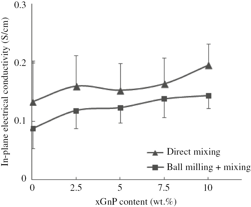
The effect of the xGnP on the in-plane electrical conductivities of the PP/SG/xGnP composites.
A larger scattering in the readings of the conductivity was recorded at different positions on the surface of the plates for direct mixed samples compared with that of the ball-milled ones. This may indicate a better homogenized composite in the case of the ball-milled plates. The results of through-plane conductivities for all types of direct mixed or ball-milled PP/SG and PP/SG/xGnP composites are shown in Table 3. The through-plane conductivity was measured at a contacting pressure ranging from 3 to 30 bars. It seems that there is no significant difference between the through-plane conductivity of composites regardless of their processing technique and slightly higher values at a higher xGnP content have reported. Moreover, the values are almost convergent to those of the in-plane conductivities, which shows an isotropic behavior of the composites.
The through-plane electrical conductivities of the PP composites.
| Sample type | Through-plane conductivity (S/cm) | |
|---|---|---|
| Direct mix | Mill+mix | |
| PP/SG | 0.133±0.031 | 0.135±0.017 |
| PP/SG/2.5 wt.% xGnP | 0.123±0.022 | 0.128±0.032 |
| PP/SG/5 wt.% xGnP | 0.109±0.060 | 0.135±0.035 |
| PP/SG/7.5 wt.% xGnP | 0.152±0.002 | 0.149±0.011 |
| PP/SG/10 wt.% xGnP | 0.208±0.016 | 0.147±0.017 |
The MWCNTs and CB were then added to improve the in-plane and through-plane conductivities of the PP/SG/xGnP composites prepared by techniques mentioned above. The MWCNTs and CB were added to the PP/SG/10 wt.% xGnP, which previously showed the highest value of electrical conductivity. The conductive fillers were added with different percentages: 2.5, 5 and 7.5 wt.%. The results of the measured in-plane and through-plane electrical conductivities are shown in Figures 3 and 4 , respectively. As the figures show, the addition of MWCNTs and CB has led to a significant increase in the electrical conductivities. The MWCNTs is more effective in enhancing the electrical properties of the composites. For instance, samples containing MWCNTs showed 60 times increase in the in-plane electrical conductivity, whereas the through-plane value has increased 75 times. The CB aggregates and MWCNTs usually create a synergistic effect with xGnP, which improves the dispersion of fillers and the link between graphite platelets [18]. Lower standard deviations are noticed by adding MWCNTs and CB, which may refer to a more homogenous structure compared with the PP/SG/xGnP composites. Again, due to the convergent values of both the in-plane and through-plane conductivities for composites containing either CB or MWCNTs, the composites can be considered isotropic.

The effect of the MWCNTs and CB on the in-plane electrical conductivities of the PP/SG/xGnP composites.

The effect of the MWCNTs and CB on the through-plane electrical conductivities of the PP/SG/xGnP composites.
A combination of MWCNTs and CB together into the PP/SG/xGnP composites and their effects on electrical conductivity were also investigated in this study. The results are shown in Table 4. About 7.5 wt.% of CB+MWCNTs was kept in composites as this percentage of either CB or CNTs previously indicated the highest values of conductivities. The combination ratios of MWCNTs:CB were 1:2, 1:1 and 2:1. The values of the in-plane and through-plane conductivities in Table 4 are found to fluctuate similar to those of the PP/SG/xGnP/5 wt% MWCNT composites. This reflects several points. First, the predominant existence of MWCNTs in the composites is mainly attributed to higher values of conductivities. Second, there is no outstanding impact on conductivity for combining both the CB and MWCNTs in the composites if these composites are compared with those containing only MWCNTs at 7.5 wt.%. Third, a slight increase in conductivities could be noticed for ball-milled composites compared with the direct-mixed ones. This might be due to the compromise of the positive and negative effects of ball milling on composites containing CB and those containing MWCNTs, respectively [21]. The comparable values of the in-plane and through-plane conductivities could also be observed for composites combining both MWCNTs and CB.
The electrical conductivities of the PP composites combined with the MWCNTs and CB.
| Sample type | In-plane conductivity (S/cm) | Through-plane conductivity (S/cm) | ||
|---|---|---|---|---|
| Mix | Ball mill+mix | Mix | Ball mill+mix | |
| PP/SG/xGnP/2.5CNT/5CB | 6.31±1.23 | 6.90±1.71 | 7.01±0.39 | 7.31±0.17 |
| PP/SG/xGnP/3.75CNT/3.75CB | 8.07±1.16 | 8.23±1.77 | 8.91±0.12 | 9.68±0.16 |
| PP/SG/xGnP/5CNT/2.5CB | 9.03±1.21 | 9.7±1.47 | 10.4±0.37 | 11.3±0.21 |
3.2 Flexural properties
The results of the flexural properties of the PP/SG and PP/SG/xGnP composites are shown in Figures 5 and 6 , respectively. The direct-mixed composites show no clear trend in the value of flexural strength by increasing xGnP content from zero to 10 wt.% and its value fluctuates with a mean value of about 17 MPa. In general, the addition of the xGnP to the direct-mixed PP/SG has no negative impact and a slight increase in flexural strength is sometimes noticed. The ball milling of the components before they are melt-mixed resulted in composites with flexural strength values that are slightly lower than those of ball-milled PP/SG composites. Again, no clear trend can be observed by comparing the flexural strengths of the ball-milled composites and their direct-mixed counterparts. The results of flexural modulus in Figure 6 show an improvement in the stiffness of both the direct-mixed and ball-milled composites with the addition of high content, mainly 10 wt.%, of the xGnP compared with the PP/SG composites. The increase is more pronounced for the ball-milled composites.

The effect of the xGnP on the flexural strengths of the PP/SG/xGnP composites.

The effect of the xGnP on the flexural moduli of the PP/SG/xGnP composites.
The incorporation of MWCNTs to the PP/SG/xGnP composites prepared by direct melt mixing slightly decreases its flexural strength, as shown in Figure 7 . The composites at all MWCNT compositions show similar strength value of about 12 MPa. The decrease in flexural modulus is also seen at 2.5 wt.% MWCNTs compared with the PP/SG/xGnP composites (see Figure 8). The addition of 10 wt.% MWCNTs to the composites improves its stiffness. The degradation in flexural strength is incompatible with the nature of the MWCNTs, which are typically used as reinforcement materials. The reinforcement effectiveness may vanish when the problem of agglomeration is highlighted. On the contrary, as shown in Figure 7, the addition of 2.5 wt.% CB improves the flexural strength to about 19 MPa, and this improvement is inversely proportional to the CB content. CB has a negative impact on the stiffness of the composites appearing mainly at 7.5 wt.% CB content. The better dispersion and homogenous distribution of the CB aggregates may result in the improvement of flexural strength.
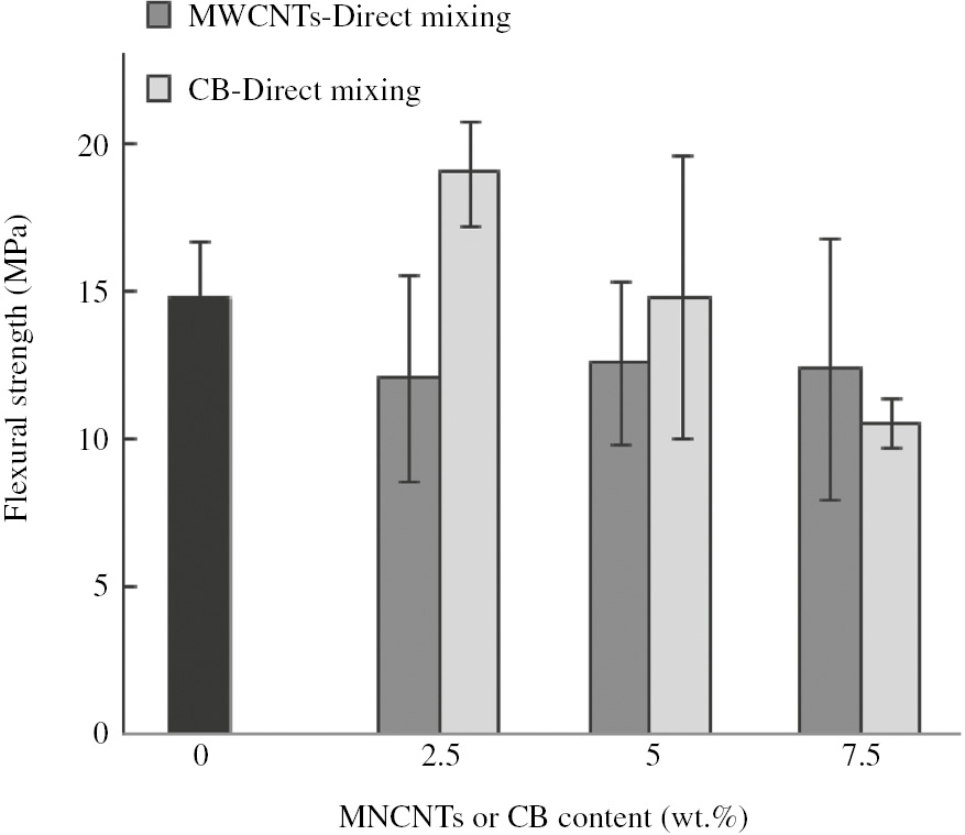
The effect of the MWCNTs and CB on the flexural strength of the PP/SG/xGnP composites.

The effect of the MWCNTs and CB on the flexural modulus of the PP/SG/xGnP composites.
Finally, the incorporation of MWCNTs and CB together into the PP/SG/xGnP composites has a positive impact on flexural strength and modulus compared with those containing either MWCNTs or CB at 7.5 wt.% (see Table 5). It appears that the ball milling of the components before melt mixing slightly lowers the flexural properties.
The flexural properties of the PP/SG/xGnP combined with the MWCNTs and CB.
| Sample type | Flexural strength (MPa) | Flexural modulus (MPa) | ||
|---|---|---|---|---|
| Mix | Ball mill+mix | Mix | Ball mill+mix | |
| PP/SG/xGnP/2.5CNT/5CB | 17.22±0.52 | 13.75±0.98 | 3.44±0.21 | 3.05±0.37 |
| PP/SG/xGnP/3.75CNT/3.75CB | 18.63±0.53 | 14.43±0.50 | 3.84±0.41 | 3.06±0.25 |
| PP/SG/xGnP/5CNT/2.5CB | 18.52±0.60 | 17.75±0.89 | 4.24±0.27 | 3.75±0.27 |
3.3 Morphological observations and discussion of results
The morphologies of the conductive fillers and the fracture surfaces of the composite plates were examined in an attempt to explain their electrical and flexural behaviors. The SEM micrographs of conductive fillers at different magnifications are shown in Figure 9. As can be seen, the SG particles have a thick flaky shape, which is irregular and sometimes appears elongated, whereas the xGnP graphene nanoplatelets have a thin flaky shape, which appears circular as can be observed at low magnification in Figure 9. The difference between the morphologies of the SG particles and xGnP is less distinguishable at high magnification, and the agglomeration of particles is noticed. The CB is found in spherical aggregates and the MWCNTs are found in bundles and entanglements.

The SEM micrographs of the MWCNTs, xGnP, CB and SG at different magnifications.
The microstructure of the fractured surface of the direct-mixed PP/SG is shown in Figure 10. It appears from the micrographs that there are some compacted platelets of SG that are oriented along the plate surface and their edges appear out of the plane of the fracture. Gaps exist between these platelets, as seen at higher magnification. Other SG particles are randomly oriented and embedded in the PP matrix. The ramifications of PP are found to be distributed not uniformly throughout the microstructure; these are observed at the edges of the oriented SG platelets and may also surround randomly oriented particles. All these findings indicate a less homogenized microstructure, which may be attributed to the inhomogeneity in the mixing process of the components. Furthermore, poor adhesion between the conductive fillers and PP and the non-uniformity existence of PP throughout the microstructure and throughout the gaps between the compacted platelets lead to poor flexural properties of the composite plates. This explains why the flexural strength value drops from 60 MPa for pure PP to less than 20 MPa for PP/60 wt.% SG composites. Moreover, the above highlighted issues hinder the formation of a continuous conductive path and explain the low values of the in-plane conductivity.

The SEM micrographs showing the fracture surface of the direct-mixed PP/SG at different magnifications shown at (A) and (B).
The fracture micrographs of the direct-mixed and ball-milled PP/SG/10 wt.% xGnP composite plates are shown in Figure 11. The microstructures of both types of composites appear similar to a large extent. The addition of the xGnP to the PP/SG composites leads to the formation of a larger portion of a structure similar to that bordered by a rectangle in the micrographs, in which the graphene nanoplatelets are randomly oriented and embedded in PP and seems more homogeneous. This might explain the improvement in the in-plane conductivity by the addition of the xGnP nanoplatelets and the improvement in flexural properties, if any. The presence of large graphite particles that bordered in ellipses, as shown in the micrographs, hinders the homogeneity of the microstructure and leads to poor adhesion and discontinuity in the formation of the continuous conductive path. The oriented compact platelets still exist but at a lesser degree.

The SEM fracture micrographs of the direct-mixed and ball-milled PP/SG/10 wt.% xGnP composites at different magnifications.
The effect of adding MWCNTs or CB or a combination of both fillers on the microstructure of the PP/SG/10 wt.% xGnP is shown in Figure 12. The presence of MWCNTs is clear in the micrograph of the PP/SG/xGnP/7.5CNT composite (Figure 12A). MWCNTs are found at the edges of the randomly oriented graphene platelets, thus connecting them to the binder. The dominant existence and strong affinity of MWCNTs can be observed at the edges of the xGnP. MWCNTs are sometimes found connected between the oriented platelets. This is positively reflected in the values of the in-plane and through-plane conductivities of the composites. The flexural properties of the composites containing MWCNTs were not as expected and this can be explained by the fact that the alignment of MWCNTs in the direction of the plane of the fracture does not enhance the reinforcing power of the composites. For the PP/SG/xGnP/7.5CB composites shown in Figure 12B, very small black spots, like pits, are seen and are assumed to be CBs that are not uniformly distributed and may be found between platelets. The presence of CB increases the conductivities in both directions but it does not do good job regarding the reinforcement. The increase of flexural strength at small portions of the CB may be attributed to a role of CB in improving the distribution of the SG and xGnP particles in the PP matrix. Finally, the structures of the composites after combining MWCNTs and CB are shown in Figures 12C and D. Gaps between the platelets and pits of CB still exist and a better distribution of MWCNTs and PP is observed.

The SEM fracture micrographs of the direct-mixed (A) PP/SG/xGnP/7.5MWCNTs, (B) PP/SG/xGnP/7.5CB, (C) PP/SG/xGnP/5MWCNTs/2.5CB and (D) ball milled PP/SG/xGnP/3.75MWCNTs/3.75CB composites at different magnifications.
In summary, the PP-based nanocomposites were prepared via two techniques: direct melt mixing using an internal mixer, and by ball milling the components before melt mixing. One-dimensional (MWCTs) and two-dimensional (CB, SG and xGnP) carbon allotropes were used as conductive fillers. The study investigated single and multiple conductive fillers and their effects on the electrical conductivity and flexural strength the PP-based nanocomposites. The in-plane and through-plane electrical conductivities were then measured and reported. The addition of the CB and MWCNTs resulted in a significant increase in the electrical conductivities due to the improvement of the homogeneity of samples and orientation of the conductive fillers. The ball milling of the components before the direct melt mixing was advantageous in enhancing the properties in case of CB, but the same is not clear in the case of composites containing the MWCNTs. Ball milling reduced the length of the MWCNTs; hence, minimal or even zero improvement of the mechanical properties was observed. The aglomeration of MWCNTs was observed in some cases, and this affected both the electrical and flexural properties of the composites. Generally, all types of PP-based composites behaved in an isotropic manner.
Acknowledgments
The authors would like to acknowledge the Al-Balqa Applied University as well as the Fuel Cell Institute/Universiti Kebangsaan Malaysia for their highly appreciated help and support.
References
[1] Yeetsorn R, Fowler MW, Tzoganakis C. In Nanocomposites with Unique Properties and Applications in Medicine and Industry, Cuppoletti, J, Ed., Croatia: Rijeka, 2011, p 317–344.Search in Google Scholar
[2] Yuana XZ, Wanga H, Zhanga J, Wilkinsona DP. J. New Mater. Electrochem. Syst. 2005, 8, 257–267.Search in Google Scholar
[3] Nagata K, Iwabuki H, Nigo H. Compos. Interfaces 1998, 6, 483–495.10.1163/156855499X00161Search in Google Scholar
[4] Dweiri R. Int. J. Mat. Res. 2012, 7, 909–914.10.3139/146.110699Search in Google Scholar
[5] Feller J-F, Petitjean É. Macromol. Symp. 2003, 203, 309–315.10.1002/masy.200351334Search in Google Scholar
[6] Omastová M, Chodák I, Pionteck J. Synth. Met. 1999, 10, 1251–1252.10.1016/S0379-6779(98)01453-2Search in Google Scholar
[7] Dweiri R, Jaafar S. J. Mater. Sci. 2007, 42, 10098–10102.10.1007/s10853-007-2092-xSearch in Google Scholar
[8] Zhang W, Dehghani-Sanij AA, Blackburn RS. J. Mater. Sci. 2007, 42, 3408–3418.10.1007/s10853-007-1688-5Search in Google Scholar
[9] Király1 A, Ronkay F. J. Polym. Eng. 2013, 33, 691–699.10.1515/polyeng-2013-0038Search in Google Scholar
[10] Suherman H, Sulong AB, Sahari J. Ceram. Int. 2013, 39, 1277–1284.10.1016/j.ceramint.2012.07.059Search in Google Scholar
[11] Dweiri R, Sahari J. AIP Conf. Proc. 2010, 1217, 559–565.10.1063/1.3377888Search in Google Scholar
[12] Onyu K, Yeetsorn R, Fowler M, Yu A, Jun YS, Prapainaina C, Prissanaroon-Ouajai W. KMUTNB Int. J. Appl. Sci. Tech. 2016, 9, 1–13.10.14416/j.ijast.2016.02.003Search in Google Scholar
[13] Antunes RA, Oliveira MCL, Ett G, Ett V. J. Power Sources 2011, 196, 2945–2961.10.1016/j.jpowsour.2010.12.041Search in Google Scholar
[14] Cunningham BD, Huang J, Baird DG. Int. Mater. Rev. 2007, 52, 1–13.10.1179/174328006X102556Search in Google Scholar
[15] Krause B, Villmow T, Boldt R, Mende M, Petzold G. Pötschke P. Compos. Sci. Technol. 2011, 71, 1145–1153.10.1016/j.compscitech.2011.04.004Search in Google Scholar
[16] Isayev AI, Jung C, Gunes K, Kumar R. Int. Polym. Process 2008, 4, 395–405.10.3139/217.2167Search in Google Scholar
[17] Jiang X, Drzal LT. J. Appl. Polym. Sci. 2012, 124, 525–535.10.1002/app.34891Search in Google Scholar
[18] Wei T, Song L, Zheng C, Wang K, Yan J, Shao B. Fan ZJ. Mater. Lett. 2010, 64, 2376–2379.10.1016/j.matlet.2010.07.061Search in Google Scholar
[19] Feng C, Ni H, Chen J, Yang W. ACS Appl. Mater. Interfaces 2016, 8, 19732–19738.10.1021/acsami.6b03723Search in Google Scholar PubMed
[20] Kalaitzidou K, Fukushima H, Drzal LT. Materials 2010, 3, 1089–1103.10.3390/ma3021089Search in Google Scholar
[21] Dweiri R. Jordan J. Mech. Ind. Eng. 2015, 9, 1–8.Search in Google Scholar
©2018 Walter de Gruyter GmbH, Berlin/Boston
This article is distributed under the terms of the Creative Commons Attribution Non-Commercial License, which permits unrestricted non-commercial use, distribution, and reproduction in any medium, provided the original work is properly cited.
Articles in the same Issue
- Frontmatter
- Reviews
- Effect of reinforcements on polymer matrix bio-composites – an overview
- A critical review on the development and performance of polymer/graphene nanocomposites
- Original articles
- Structural design and analysis of composite blade for horizontal-axis tidal turbine
- Mechanical alloying of CuFe-alumina nanocomposite: study of microstructure, corrosion, and wear properties
- Analysis of the bending and failure of fiber metal laminates based on glass and carbon fibers
- Thermal insulation of silica aerogel/PMMA composites with amino-capped polydivinylsiloxane phase interfaces
- Degradable Mg alloy composites using fly ash cenospheres
- Experimental study on the durability of FRP bars reinforced concrete beams in simulated ocean environment
- Effect of geometrical parameters on the effective elastic modulus for an X-type lattice truss panel structure
- Thermal cycling of composite laminates made of out-of-autoclave materials
- Optimization of thermal conductivity in composites loaded with the solid-solid phase-change materials
- Developing polymer composite-based leaf spring systems for automotive industry
- Structure-property-processing investigation of electrically conductive polypropylene nanocomposites
- Microstructure evaluation, thermal and mechanical characterization of hybrid metal matrix composite
- Study of one-dimensional cure simulation applicable conditions for thick laminates and its comparison with three-dimensional simulation
- Development of a user-friendly drilling evaluation database system of CFRP
- Incorporating oxygen-free copper to improve the microstructure and mechanical properties of friction-stir-welded joints for aluminum alloys
- Analytical solution on dosage of self-healing capsules in materials with two-dimensional multi-shaped crack patterns