Effects of cutouts on natural frequency of laminated composite plates
-
Ahmet Erkliğ
 ,
Mehmet Bulut
,
Mehmet Bulut

Abstract
In this study, the effects of cutouts (circular, square, triangular and elliptical), cutout position and fiber orientations of laminated composite plates on natural frequencies are investigated. In order to study the effects of cutouts on natural frequencies of the composite plates, experiments have been carried out. Finite element analysis is also performed to predict the effects of different cutouts, cutout position, fiber orientation and length of the plate on natural frequencies for E-glass/polyester. Several outcomes and behavioral characteristics are discussed. These outcomes include the cutout shape, cutout orientation and fiber orientation angle. It has been seen that all of the experimental and finite element results are very close to each other. It has also been concluded that the natural frequency of composite plate is affected by the fiber orientation and cutout location but not considerably affected by cutout shape. The results show that fiber orientation angle and cutout location are the most important parameters on the natural frequency. When the fiber orientation angle increases, both bending and twisting natural frequencies decrease. Maximum natural frequency occurs on [(0/90)4]S laminated plate.
1 Introduction
Fiber reinforced composite materials are very important in engineering applications due to their excellent features such as high strength-to-weight and high stiffness-to-weight ratios. Thus, they are mainly used in civil, marine and the aerospace industry. In a structural design, elimination of resonant frequency is very important as resonance effects can induce failure of constructed structures. Prediction of natural frequency and working optimum frequency in structures is therefore required.
Cutouts are mainly used in practical applications such as damage inspection, altering the natural frequency, and access ports for mechanical and electrical systems. Natural frequency and damping properties of composite structures have been investigated by many researchers [1–16]. Chandrashekhara et al. [1] presented free vibration of symmetrically laminated composite beams and obtained exact solutions for free vibration. In calculations, rotary inertia and first-order shear deformation effects were considered for the analysis. Qatu [2] studied symmetrically laminated composite plates and performed effects of various parameters such as material, fiber orientation and boundary conditions on the natural frequencies and mode shapes. Narita and Leissa [3] performed free vibration of cantilever and rectangular angle-ply and cross-ply laminated composite plates. Natural frequencies were calculated using Ritz method, and different parameters such as material and fiber angle were considered. Huang and Sakiyama [4] developed a function for free vibration of rectangular plates with different cutout shapes such as circular, rectangular and triangular. In order to calculate free vibration of rectangular plates with an arbitrarily located hole with different shapes, discrete solution was proposed. In discrete solution, the Green functions were used to transform a free vibration problem into the eigenvalue problem. Khdeir and Reddy [5] developed a complete set of linear equations for free vibration of cross-ply and angle-ply composite plates using second-order theory and obtained exact analytical solutions for moderately thick and thin plates. Turvey et al. [6] investigated effects of anisotropy, hole size ratio and boundary conditions on the natural frequency of square pultruded glass reinforced plastic plates. Clamped, simply supported and free edge supports were considered as boundary conditions. Vibration experiments were done on plates with central circular cutouts. Experiment and finite element mode shape results were in accordance with each other. Liew et al. [7] analyzed free vibration of rectangular plates with central rectangular cutouts. Combinations of simply supported and clamped boundary conditions were used. Won and Sung [8] presented free and forced vibration analysis of laminated composites. Assumed strain method and constitutive equation in the finite element of composite plates were used in the study. Exact solutions were presented to show application of formulation to rectangular isotropic and rectangular composite plates for free vibration. Aydogdu [9] studied vibration analysis of angle-ply laminated beams with different boundary conditions. Combinations of free, clamped and simply supported edge conditions were considered. Free vibration frequencies were obtained using the Ritz method with a 3 degrees of freedom shear deformable beam theory. Moon and Sangbo [10] analyzed vibration analysis of rectangular plates using the coordinate coupling method. Analytical results were compared with finite element and experimental results for rectangular plates. Mohammed et al. [11] investigated the dynamic behavior of composite beams using the finite element method.
As seen from the above literature, free vibration analysis of composite plates has been studied by many researchers using the finite element method. Furthermore, circular central cutout effect and the fiber orientation angle have been studied, but the combination of variables considered during previous studies is still limited. In this study, effects of fiber orientation, different cutout shapes (circular, square, triangular and elliptical), cutout orientations, cutout sizes and length of the plate on the natural frequency of laminated composite plates are taken into consideration. Cantilever boundary condition is considered. ANSYS package program (ANSYS, Inc., Berkeley, USA) is used in the numerical studies.
2 Mathematical formulation
If the length of the plate is so much greater than other dimensions, the composite plate can be considered as a thin beam [12]. In this study, dimensions of plates are considered as 150 mm long (L), 20 mm wide (W) and 1.6 mm thick (t) with eight layers as shown in Figure 1. The Euler-Bernoulli beam theory is used in formulations and calculations. It is assumed that plane cross sections remain plane and normal to the centerline after the deformation and both rotary inertia. Shear deformation effects are neglected.
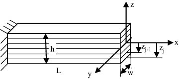
Cantilever laminated composite beam.
The Euler equation for a beam can be written as follows [12].

w(x,t) can be written as another form by separation of the variable

where X=X(x) and ϕ=ϕ(t). Substitution of Eq. (2) into Eq. (1) yields

Eq. (3) can be written as

When Eq. (4) is separated by two parts

where  and α is a constant.
2.1 Boundary conditions of cantilever beam
For clamped sides:
For free sides:

Eqs. (7) and (8) boundary conditions subjected to Eq. (2) yield

and

Eq. (10) is solved using Mathematica, and non-dimensional frequency parameters are obtained (Table 1).
Non-dimensional frequency parameters (β) of cantilever beam.
| Beam | α1L | α2L | α3L |
|---|---|---|---|
| Clamped-free | 1.875 | 4.694 | 7.855 |
3 Material properties
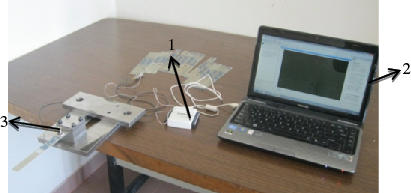
In this study, woven glass polyester was used to produce laminated composite plates. Mechanical properties of the plates were obtained using Shimadzu AG-X series tensile test machine (Shimadzu Corporation, Kyoto, Japan) as listed in Table 2. The composite plies were laid up to form 8-ply laminates having [θ]8 stacking sequences, and dimensions of plates were taken as 150 mm×20 mm×1.6 mm (Figure 2). Fiber orientations were chosen as [(0/90)4]S, [(45/-45)4]S and [(30/-60)4]S. Circular and rectangular types of cutout were prepared for the experiments. For each fiber orientation, nine test samples were prepared for each cutout type; one out of three of them had a central circular cutout of 10 mm diameter (A) and another one out of three had a square cutout of 10 mm side length (A) as shown in Figure 3. In total, 27 specimens were prepared for the experiments.

Laminated glass-polyester composite plates.

Laminated composite plate with cutout. (A) Circular cutout, (B) rectangular cutout.
Mechanical properties of specimens.
| E1=E2 (GPa) | ν12=ν21 | G12=G21 (GPa) |
|---|---|---|
| 20.50 | 0.21 | 3.56 |
4 Experimental modal analysis
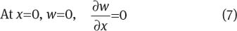
An accelerometer (Brüel & Kjær Sound & Vibration Measurement A/S, Nærum, Denmark) and data acquisition card (NI USB-6009, National Instruments Corporation, Austin, USA) were used in the experimental setup as shown in Figure 4. One end of the specimen was fixed in a rigid support while the other end was free to vibrate. The 20 mm initial displacements were given as an input and signals were captured by an accelerometer. Captured voltage signals were transformed to the frequency signals using fast Fourier transform using the MATLAB program. [(0/90)4]S, [(30/-60)4]S and [(45/-45)4]S cross-ply laminated composite plates without cutout (w-c), with square cutout (s-c) and circular cutout (c-c) were considered in the modal analysis.
Experimental setup. (1) Data acquisition card, (2) computer, (3) accelerometer.
5 Numerical studies
Natural frequencies of the composite plates were performed using the ANSYS12.0 finite element analysis program. During the analyses, the effects of circular, triangular, square and elliptical cutouts on natural frequency were investigated. In the analysis, five different fiber orientation angles, ten different widths over cutout length ratio, seven lengths over width ratio and five modes of frequency were used. Length (L) and width (w) of the plate were taken as 150 mm and 20 mm, respectively. The thickness of the plate was taken as 1.6 mm and the number of layers was taken as 8.
In order to inspect the twisting frequency modes of the composite plate, SHELL91 element type with 250/30 division is selected. SHELL91 [17] element geometry illustrated in Figure 5 can be used for layered applications to produce mesh structure. The element has six degrees of freedom at each node: translations in the nodal x, y and z directions and rotations about the nodal x, y and z axes.
![Figure 5 SHELL91 geometry [17].](/document/doi/10.1515/secm-2012-0120/asset/graphic/secm-2012-0120_fig5.jpg)
SHELL91 geometry [17].
Natural frequencies of cantilever plate with (c-c), (s-c) and (w-c) were calculated using ANSYS in terms of fiber orientation angle and compared with the experimental results as shown in Table 3. As seen in Table 3, numerical and experimental results are in close agreement with each other.
Natural frequencies of laminated composite plate.
| Fiber orientation angle | Mode 1 | Mode 2 | ||||||||||
|---|---|---|---|---|---|---|---|---|---|---|---|---|
| ANSYS | Exp. | ANSYS | Exp. | |||||||||
| w-c | s-c | c-c | w-c | s-c | c-c | w-c | s-c | c-c | w-c | s-c | c-c | |
| 0 | 40.5 | 38.7 | 39.7 | 40 | 38 | 39 | 253.4 | 244.0 | 240.5 | 253 | 243 | 244 |
| 30 | 32.8 | 34.2 | 33.5 | 35 | 33 | 32 | 205.1 | 203.3 | 210.1 | 218 | 200 | 209 |
| 45 | 31.1 | 31.2 | 31.4 | 29 | 30 | 29 | 194.6 | 197.4 | 199.7 | 201 | 196 | 202 |
5.1 Effect of fiber orientation angle
In this study, [(0/90)4]S, [(15/-75)4]S, [(30/-60)4]S and [(45/-45)4]S fiber orientations were used in order to investigate the effect of fiber orientation angle on the natural frequencies. The first five modes of frequency were considered in the numerical studies. Figure 6 shows the effects of the fiber orientation angle on natural frequencies. It shows that the laminate with fibers [(45/-45)4]S angles has lower natural frequencies than other angles. The laminate with fibers [(0/90)4]S angles has a greater natural frequency in bending modes (modes 1, 2 and 5) because 50% of the fibers are oriented at 0° in [(0/90)4]S, and thus are appropriate for bending.

Effects of fiber orientation on natural frequencies.
5.2 Effect of cutout position
In order to investigate the effect of cutout position (CP) on natural frequencies of the composite plates, circular CP is changed from -40 mm to +40 mm on the x-axis as shown in Figure 7.
Cutout position of laminated composite plate.
Only the first two vibration mode frequencies were investigated for square, circular, triangular and elliptical cutouts for the [(0/90)4]S fiber orientation. The effect of CP on the natural frequency is shown in Figure 8.

Change in cutout position for (A) first mode and (B) second mode.
As shown in Figure 8A, when cutout approaches the clamped edge, the natural frequency of the first mode is decreased. In Figure 8B, the natural frequency of the second mode at the center of the plate is lower than any other CP.
5.3 Effect of cutout size
The effect of cutout size on natural frequencies was investigated by increasing cutout size while the width of the plate is taken as a constant. Circular and square type of cutouts were preferred and located at the center of the plate for the analysis. As can be seen in Figure 9, the natural frequencies of composite plates with circular and square cutout decrease while the width of plate over cutout size (w/A) ratio increases.

Cutout size for (A) circular cutout and (B) square cutout.
5.4 Effect of length of plate
Change of natural frequency for different length over width ratios is shown in Figure 10. The central cutout is used. Its position and diameter are chosen as constant. Natural frequency decreases with increasing plate length over width ratio, but natural frequency behavior generally stays the same for each cutout.
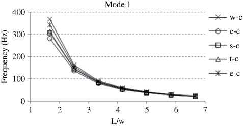
Effects of length of plate on natural frequencies.
Mode shapes of cantilever laminated composite plate are given in Figure 11. As can be seen from the figure, first, second and fifth modes of frequencies are bending, whereas the third and fourth modes of frequencies are torsional vibration frequencies.
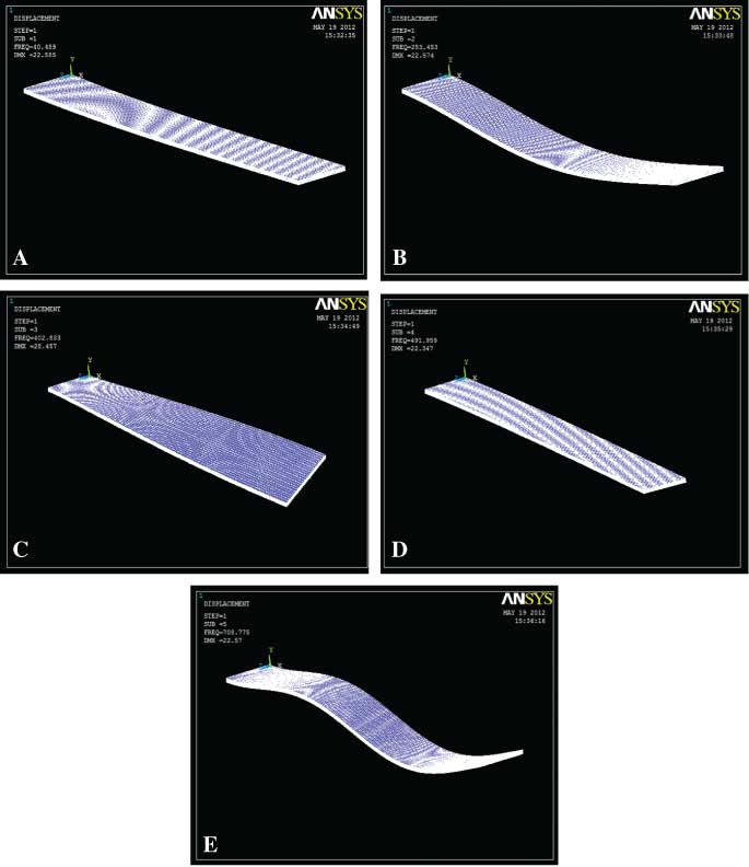
Mode shapes of composite beam (w-c). (A) Mode 1, (B) mode 2, (C) mode 3, (D) mode 4, (E) mode 5.
6 Conclusions
In this study, detailed parametric studies have been carried out to reveal the effects of cutout size, cutout type, cutout position, length of the plate and fiber orientation angle on the natural frequencies of the laminated composite plates. The numerical results were compared with experimental results and theoretical results. Numerical results are in close agreement with experimental and theoretical results. The main conclusions that can be drawn from this investigation are:
Natural frequencies of the laminated composite plate are affected by the stacking sequence, and it allows to achieve the desired natural frequencies without changing its geometry or without changing its weight.
When the fiber angle increases, the natural frequencies decrease. Maximum natural frequency occurs on [(0/90)4]S laminated plate.
A rectangular plate without cutout has greater natural frequencies than plates with the square and circular cutouts.
Effects of cutout location were also investigated. Natural frequency for the first mode is decreased while cutout approaches the clamped edge. Natural frequency for the second mode is decreased while cutout approaches the center of the plate.
Natural frequencies for the first three modes and circular and square cutouts are decreased by increasing the w/A ratio.
Natural frequency decreases with increasing plate length over width ratio, but natural frequency behavior generally stays the same for each cutout.
References
[1] Chandrashekhara K, Krishnamurthy K, Roy S. Compos. Struct. 1990, 14, 269–279.Search in Google Scholar
[2] Qatu MS. Int. J. Solids Struct. 1991, 28, 941–954.Search in Google Scholar
[3] Narita Y, Leissa AW. J. Sound Vib. 1992, 154, 161–172.Search in Google Scholar
[4] Huang M, Sakiyama T. J. Sound Vib. 1999, 226, 769–786.Search in Google Scholar
[5] Khdeir AA, Reddy JN. Comput. Struct. 1999, 71, 617–626.Search in Google Scholar
[6] Turvey GJ, Mulcahy N, Widden MB. Compos. Struct. 2000, 50, 391–403.Search in Google Scholar
[7] Liew KM, Kitiponchai S, Leunh AYT, Lim CW. Int. J. Mech. Sci. 2003, 45, 941–959.Search in Google Scholar
[8] Won HL, Sung CH. Comput. Mech. 2006, 39, 41–58.Search in Google Scholar
[9] Aydogdu M. J. Reinf. Plast. Compos. 2006, 25, 1571–1583.Search in Google Scholar
[10] Moon KK, Sangbo H. J. Sound Vib. 2007, 306, 12–30.Search in Google Scholar
[11] Mohammed FA, Goda IGM, Gagal AH. Int. J. Mech. Mechatronics 2010, 10, 59–68.Search in Google Scholar
[12] Leissa W, Qatu M. Vibrations of Continuous Systems, 1st ed., McGraw-Hill Education: New York, 2011, pp. 103–110.Search in Google Scholar
[13] Garg AK, Khare RK, Kant T. J. Sandwich Struct. Mater. 2006, 8, 205–235.Search in Google Scholar
[14] Lei X, Rui W, Shujie Z, Yong L. J. Compos. Mater. 2010, 45, 1069–1076.Search in Google Scholar
[15] Chen CS. J. Reinf. Plast. Compos. 2005, 24, 1747–1758.Search in Google Scholar
[16] Topal U, Uzman Ü. Mater. Des. 2008, 29, 1512–1517.Search in Google Scholar
[17] ANSYS Procedures. Engineering Analysis System Verification Manual, Swanson Analysis Systems, Inc.: Houston, TX, 1993, Vol. 1.Search in Google Scholar
©2013 by Walter de Gruyter Berlin Boston
This article is distributed under the terms of the Creative Commons Attribution Non-Commercial License, which permits unrestricted non-commercial use, distribution, and reproduction in any medium, provided the original work is properly cited.
Articles in the same Issue
- Masthead
- Masthead
- Original Articles
- Mechanical and wear behavior of vinyl ester-carbon/cement by-pass dust particulate filled homogeneous and their functionally graded composites
- Microscopic fracture mechanisms of octavinyl polyhedral oligomeric silsesquioxane-containing hybrid nanocomposite materials
- Microstructure and corrosion properties of 5A06 aluminum matrix surface composite fabricated by friction stir processing
- Microstructure characteristics of laser alloying composite coatings in nitrogen protective atmosphere
- Microstructure performance of the ceramics-reinforced laser alloying composite coating on titanium
- Effects of matte coating on the paper surface and print density
- Preparation and characterization of bone-like hydroxyapatite/poly(methyl methacrylate) composite biomaterials
- Investigation of machinability in Al-MgO composites produced by melt-stirring
- A non-linear elastic-plastic stress analysis in a ductile double-lap joint
- Effect of fiber type on strength of quasi-isotropic bonded/unbonded plastic composites subjected to tension and compression loadings
- Computing transverse elasticity modulus of composites using boundary integral equation method
- Effects of cutouts on natural frequency of laminated composite plates
- Frequency optimization of laminated annular circular plates
- Enhancement of flexural performance of wood beams using textile fabrics