UAV image and intelligent detection of building surface cracks
-
 ,
,

Abstract
To solve the problems of low efficiency and high risk of crack detection in high-rise buildings, the author proposes a building crack image acquisition and processing system based on unmanned aerial vehicle (UAV), expounds the working principle of the system, and analyzes the selection of hardware in the system. The experiment is carried out by combining the acquisition system with the image processing system of the ground station. Based on the characteristics of building surface crack image, an adaptive filtering method is introduced to improve the classic system file checker combination method. The experimental results show that the accuracy of Canny’s method was 96.88%. Canny-based crack target detection method is trained and tested on the crack data set to obtain the classification results and the best detection effect. It is proved that the Canny algorithm based on UAV images can effectively detect cracks on building surface.
1 Introduction
The acquisition of remote sensing images is fast and simple, the amount of image information is huge, the information application is wide, the types of ground objects included are various, and the amount of information on various ground objects in the image is huge. High-resolution remote sensing image can not only observe and identify different ground object targets such as vehicles, pedestrians, traffic signs, buildings, infrastructure, and so on, but also has high application value from the image to obtain the characteristic texture, structure information, and surface change information of various ground objects. There are applications of remote sensing images in various fields today. Currently, remote sensing technology has developed rapidly in terms of space, time, and hyperspectral resolution, but there are many limitations in the collection and application of traditional remote sensing image information [1]. On the one hand, the development of traditional remote sensing platform and sensor technology is slow, and image acquisition is limited and multiple acquisition is easy to be interfered with by various external conditions. On the other hand, the rapid acquisition of small area and high-resolution image data has problems such as high cost, poor cost performance, and easy to be affected by external environmental factors, which seriously limits the further popularization of remote sensing technology [2]. With the continuous development of science and technology, the emergence of unmanned aerial vehicle (UAV) technology with the characteristics of low cost, easy access, high image resolution, strong timeliness, and easy operation, which carries the traditional remote sensing platform, has well solved the problem of traditional aerial photogrammetry, and it can not only quickly obtain high-resolution remote sensing images of small areas but also has a wider range of technical applications, which well complements and improves the current aerial remote sensing monitoring system [3]. In the current trend of rapid development of satellite remote sensing and general aerial remote sensing, light and small low-altitude remote sensing has become an indispensable and important technical means in the three-dimensional monitoring system and one of the main directions of the development of aerial remote sensing technology in the future. With the rapid development of science and technology, energy, and material technology, UAV technology has also made considerable progress. With the characteristics of low cost, easy access, high image resolution, strong timeliness, easy operation, and few external factors, the UAV aerial survey technology with remote sensing platform has attracted more and more attention. In recent years, with the rapid development of geospatial information technology, light and small aviation with fast response ability, flexibility, and easy operation and application has risen rapidly in the field of aerial remote sensing in recent years. The close combination of UAV and surveying and mapping provides a more efficient and convenient surveying and mapping method for traditional surveying and mapping, and has become one of the new main forces in the field of aerial remote sensing [4].
The remote sensing system of low-altitude light and small UAV can become one of the indispensable main forces of the current general aerial photography and satellite remote sensing system. The main advantages are as follows: First, the UAV acquisition technology is simple and easy to learn; the flight plan can be customized according to user’s needs; and the flight area and flight overlap rate can be designed as required. Second, the flight height of UAV is relatively low, and the flight height is within the safe range, which is not easy to be affected by high-altitude clouds and external weather and natural environment factors. UAV navigation can quickly obtain high-resolution images at different scales by adjusting the navigation height and overlap according to the actual needs. The last point is that the UAV has low requirements for takeoff conditions, no need to establish special runways and other auxiliary conditions, and the technology is widely applicable. With the continuous progress of remote sensing technology, the UAV technology has also made considerable progress, the UAV image acquisition method is more convenient and fast, and the image resolution is higher and the information is richer. Not only has the traditional surveying and mapping been widely used but also the high-resolution UAV image has emerged in the fields of natural science and people’s livelihood. It can not only serve as an important data source for the development of agriculture, forestry, geology, ocean, and other fields but also plays an indispensable role in urban planning and urbanization process [5].
The development of traditional remote sensing image information detection and processing algorithms is relatively slow, the traditional ground feature information detection mainly relies on time-consuming and labor-intensive manual collection, and the accuracy of the obtained ground feature information is not high and the information cannot be fully utilized. Therefore, the gap between a large amount of image data and backward algorithm research is becoming larger and larger, which makes the manual detection workload huge and inefficient, and to some extent, it also hinders the development of remote sensing image ground feature information technology. The main use value of drone images is reflected in the attribute information and spatial structure information of various objects in the images. Therefore, achieving fast, intelligent, and automatic detection of ground feature information in remote sensing images has always been one of the urgent problems to be solved in remote sensing technology.
Most of the traditional methods of building information detection in remote sensing images use image information and traditional segmentation, classification, edge detection, and other methods to achieve building detection in remote sensing images. Such methods have great limitations, and there are many difficulties to overcome in practical applications. Therefore, based on the original algorithm, the author introduced a new idea: building detection in UAV image based on depth learning. Deep learning uses massive data and neural network models, through iterative learning and training of the neural network model built on the attribute features of buildings in massive UAV images, to continuously improve the accuracy of classification and prediction of the established detection model until it meets the experimental requirements. The deep learning construction model has a stronger generalization ability and deeper network structure. It can abstract the inherent characteristics of data without manually designing relevant description rules, avoid the problem of target feature selection in traditional detection problems, improve the model’s ability to describe target features, and provide a more general and concise solution to the problem of building detection.
Among these automated detection technologies, the most intuitive and flexible one for our human eyes is computer vision technology. By using drones equipped with cameras to capture images or videos of building exterior walls for crack detection, it can effectively solve the shortcomings of manual onsite investigation methods. In the application of computer vision technology in crack image detection, traditional crack image detection and extraction methods have two shortcomings:
In most cases, feature extraction, classifier training, and final image classification require experienced engineers who have been engaged in image processing research for many years to design and implement. These processes are experience driven and to some extent fail to achieve automatic processing;
Although many domestic and foreign scholars have conducted in-depth research on crack detection. However, as for how to evaluate the degree of damage to wall cracks after crack detection and extraction, as well as how to classify and quantify wall crack information, to provide a reliable reference data indicator for building maintenance and management, there is currently no in-depth research on this existing problem.
With the rapid development of the domestic construction industry, cracks may appear on the surface of early high-rise buildings, affecting their normal use. Surface cracks can develop into destructive deep and long cracks, thereby affecting the overall integrity of buildings. Timely detection and maintenance of building surface cracks can provide a certain reference and basis for the quality evaluation of buildings, which is conducive to reducing repair costs and ensuring the safety of buildings and individuals. Currently, most quality and safety hazards represented by building surface cracks are inspected manually. The efficiency of manual inspection is low, and the detection results are not objective. The subjective factors of the detection personnel have a significant impact, which cannot meet the needs of intelligent building crack detection. Overall, traditional building crack image acquisition and processing technology is still in the basic stage, and its functions are not comprehensive enough. This article proposes a UAV-based image acquisition and processing system for building surface cracks, which addresses the issues of difficulty in obtaining images of surface cracks in high-rise buildings and complex background of wall cracks.
2 Literature review
Drones mainly include helicopters, fixed rotor, multi rotor, and other types. The drones used in this study are mainly multi rotor four rotor drones.
The UAV was first developed in 1920, and especially after World War II, the UAV developed rapidly and was discovered and applied by sharp people in various fields. Nowadays, countries all over the world have launched research and development of UAV application technology in both military and civil fields, with thousands of types developed. Among them, more than 500 have been transformed into products and applied to various fields. UAV is the most widely used in the military field, with the development of society and the popularization of core technology. Now it is also slowly developing toward the field of civil UAVs, such as logistics UAVs for air transportation, geographic mapping UAVs, agricultural plant protection UAVs, and so on. Currently, the technology level of UAV is mainly in the United States, followed by Japan and the United Kingdom. With the development of China and the improvement of its scientific and technological level, China has also achieved remarkable growth in the field of UAV technology.
Currently, the detection of cracks in walls in China is generally concentrated in the stage of manual screening. The method used by inspectors to identify cracks on the exterior wall still relies on visual inspection, while inspectors use manual measurement to detect cracks on the wall. The detection of wall cracks is based on traditional detection methods such as fixed lifting ropes for close-range detection, the use of vision extension equipment to assist in observation and detection, the establishment of close-range detection equipment and instruments on site, and the use of drone aerial photography to obtain wall image data combined with human eye observation. There are many shortcomings when using manual methods to detect wall cracks:
Low execution efficiency: It takes a considerable amount of time.
High cost: Hiring a large amount of labor, whether it is building close-range detection equipment or carrying monitoring vehicles, may occupy pedestrian or lane areas, affecting the normal travel of people or vehicles.
Low detection data accuracy: Especially during fatigue, the eyes are affected by the human body, which can lead to significant deviation in the data they see.
High risk: For high-rise buildings, traditional manual operation methods pose a significant threat to the personal safety of workers.
After the aforementioned analysis, it is difficult to provide better detection data based on traditional manual detection methods for wall cracks in buildings with increasing maintenance and detection tasks year by year. So there is an urgent need to find a new crack detection method to complete efficient, high-precision, and low-cost detection tasks to better achieve daily maintenance and inspection of high-rise buildings.
Chen et al.’s computer vision and deep learning technology has become promising solutions for automating image-based detection processes. However, for detecting faade cracks from images captured by drones, existing deep learning solutions may not perform well due to complex background noise caused by different faade components and materials [6]. Gao et al. proposed an optimal adaptive selection model based on depth learning (RetinaNet AOS) for fast and accurate semantic segmentation of tunnel crack images. The algorithm uses region of interest merging masks to obtain the minimum detection area of cracks in the field of view [7]. Dan and Dan proposed an automatic identification technology for bridge surface cracks suitable for mobile machine vision detection. The core of this technology is to obtain high-precision two-dimensional spectrum estimation of crack images using two-dimensional amplitude and phase estimation methods (ab.2D-APES) and then enhance the crack information by filtering low-frequency information to achieve automatic recognition of crack targets in the image [8].
On the basis of the current research, we propose a building crack image acquisition and processing system based on UAV, expound the working principle of the system, analyze the selection of system hardware, and combine the acquisition system with the image processing system of ground station.
3 Intelligent detection of building surface cracks
3.1 Overall system scheme and principle
The system mainly includes the main control system, image acquisition device, auxiliary lighting system, attitude control system, positioning control system, image wireless transmission, and ground station image processing system. The control system uses STM32F103ZET6 as the main control chip, uses image sensor OV7670 and a strong light source to form a crack image acquisition system, and carries MPU6050 six-axis sensor to detect the flight attitude of the UAV and control the yaw angle. UAV positioning control system is based on the S1216F8-BD module and optical flow module. The nRF24L01 wireless transceiver module is used for communication control and image data transmission, and the ground station MATLAB image processing tool is used to analyze and process the building surface crack image. The overall structure block diagram of the system is shown in Figure 1.

Overall system structure block diagram.
3.2 Design of ground station image processing system
On the basis of mastering the characteristics of building cracks, combined with UAV and image processing technology, through analyzing the image transmitted by the UAV to the ground station, using the MATLAB software platform, we can intelligently and quickly detect the features of the cracks on the building surface, so as to deal with and repair the cracks on the building surface in time [9]. An intelligent building crack image acquisition and processing system is realized through the collection of building surface cracks, image preprocessing, image edge detection and extraction, image binarization, image feature measurement, and so on. The image processing flow is shown in Figure 2.

Flowchart of image processing.
3.3 Image preprocessing method of building surface cracks
To reduce the interference of surrounding factors in the acquisition process, increase the contrast of the crack image, and improve the image quality, it is necessary to preprocess the building surface crack image before crack analysis. According to the analysis results of the building surface crack image and the crack recognition difficulties in Chapter 2, it is the key to detect and remove the isolated interference pixels in the image. At the same time, for the surface that has been eroded by rain for a long time, linear transformation and histogram correction need to be carried out after graying, and by adjusting the gray value of pixels in the building surface crack image, the image will be transformed into a form that is easy to be processed in the later stage [10].
According to the characteristics of building surface cracks and crack images collected by UAV, on the basis of analyzing the processing effects of various image transformation methods, the author uses a combination of image smoothing and histogram gray stretching to remove isolated noise, improve the contrast of the crack part in the image, and better separate the crack part in the image.
In the stage of image smoothing, after trying a lot of classic and improved image-smoothing algorithms, it is found that a lot of image smoothing algorithms reduce the quality of the image and weaken the edge information of the image while suppressing noise. Most of these image smoothing algorithms need to manually set key parameters related to the smoothing effect, such as Gaussian filtering. However, due to the different types of building surface materials and the different degrees of erosion, the building surface crack images are also different, and a single and fixed parameter cannot meet the smooth requirements of all building surface crack images. To solve this problem, after testing and effect comparison, it is found that the adaptive filtering method performs well in the smooth processing of the crack image. Therefore, the author uses the adaptive smoothing filter as the smoothing method in the preprocessing stage [11].
The adaptive smoothing filtering method uses a small average weighted template to perform iterative convolution operation with the original image. During the iteration, the weighting coefficient is adaptively changed according to the surrounding pixel values. This method can sharpen image edges while suppressing noise and improve the efficiency of edge detection. For two-dimensional image
Edge retention amplitude coefficient h; (h ≥ 1)
Calculate gradient component by difference
(1)(2)Calculate the weighting coefficient
(3)Image filtering
Among
In the aspect of histogram gray level transformation and equalization of image, similar to the case of smooth filtering, the traditional histogram gray level transformation methods mostly deal with the complete gray range of a single crack image. Due to the large difference in crack images, the processing process is difficult to have strong pertinence [12]. At the same time, the processing amount of crack image is large, and the efficiency of histogram gray level transformation and equalization is low. To enhance the contrast of the building surface crack image, after the algorithm test and analysis of the research results of other scholars, the author determined the basic method, which mainly adopts the system file checker (SFC) combination method, a processing method proposed by Yin Lan, which integrates multiple processing technologies. The basic idea of this method is as follows:
The improved histogram gray stretching method is used to enhance the contrast of the image. Suppose the image to be processed is f(x, y), and g(x, y) is the result of using this method to enhance the contrast of the crack part, then the algorithm can be expressed as follows:
(6)where a is the gray threshold of the brighter part and b is the gray threshold of the darker part. When the gray value of a point in the image is less than a, set the gray value of the point to 0. When the gray value of a point is greater than a, set the gray value of the point to 255. Finally, the gray level in the middle is equalized between 0 and 255. The test shows that the original image can be processed several times by using the contrast enhancement algorithm, and the ideal effect can be obtained. In the SFC combination method, the method is first used for 10 consecutive processing times [13].
The four neighboring areas of the image are smoothed 10 times on average, and Laplace sharpening is performed once, and this step is repeated 10 times.
The improved histogram stretching method is used to enhance the image contrast 10 times.
The image is smoothed five times on average in four neighboring areas, and the contrast is enhanced 15 times by the histogram stretching method.
In the aforementioned SFC combination method, the four-neighborhood average smoothing algorithm is used as the image smoothing method. This method reduces noise at the cost of image blur. The larger the template size is, the more significant the noise reduction effect is. However, there are large differences in the image of cracks on the building surface, and the use of this simple average smoothing method is not targeted. In addition, this method is too complex and has many processing steps, which affects the efficiency of crack image enhancement. Therefore, the author uses the adaptive filtering method to replace the four-neighborhood average smoothing algorithm in the SFC combination method to improve the SFC combination method [14]. After many experiments and tests, it is found that the improved image enhancement algorithm for building surface cracks is better than the SFC combination method, and the processing efficiency is significantly improved. The specific steps of the improved SFC combination method are as follows:
Same as step 1 in the original SFC combination method.
The image is smoothed by adaptive filtering once and sharpened by Laplace once, and the step is repeated four times.
The improved histogram stretching method is used to enhance the contrast of the crack image twice.
The adaptive filter is used to smooth the crack image twice, and the improved histogram stretching method is used to enhance the contrast five times.
3.4 Crack extraction
The extraction of cracks includes two parts: coarse extraction and fine extraction. First, the obtained exterior wall image of large buildings is preprocessed by gray-scale conversion, gray-scale linear transformation enhancement, bilateral filter and denoising, and then combined with OpenCV to achieve rough extraction of cracks and segmentation of foreground and background. When the bilateral filter is used for denoising, some large noises are sometimes left behind, so a threshold H is set to filter all connected domains after rough extraction of cracks, and the connected domains whose area is less than the threshold are removed to obtain the rough extracted binary image of wall cracks. H depends on the specific situation. The empirical value obtained from the experiment is 10–15, which is more appropriate.
Using the connected domain geometric parameter screening method to achieve fine extraction of cracks. Cracks are generally considered as slender targets with a certain length and direction, characterized by continuity, significant aspect ratio, and radial orientation. The method of identifying cracks based on these constraints is called the connected domain geometric parameter screening method. There are four specific identification indicators for cracks:
Area of connected domain: refers to the number of pixels in the connected domain after binarization.
Length–width ratio of the minimum bounding rectangle of the connected domain: represents the extension of the connected domain, and the ratio of the length to width of the target minimum bounding rectangle.
Rectangularity of connected domain: it indicates the similarity between the shape of the connected domain and the rectangular shape, which is measured by the ratio of the area of the connected domain to the area of its minimum bounding rectangle.
The circularity of a connected domain: represents the similarity between the shape of the connected domain and the circular shape, measured by the ratio of the area of the connected domain to its minimum circumscribed circle area.
4 Experimental results and analysis
After building a complete UAV image acquisition system, the angle and position of the image sensor and auxiliary light source are properly adjusted. Through wireless transmission, the acquired crack image can be viewed at the ground station, and the imaging effect is adjusted appropriately according to the image quality until the crack image is clear. The ground station image-processing system is based on MATLAB R2019a. The MATLAB image processing toolbox contains the basic functions and general algorithms of digital image processing, and at the same time, it provides a program compilation platform for the secondary development [15]. There are eight waypoints located in this verification, the whole flight time is about 150 s, the data sampling frequency is 10 Hz, and a total of 1,500 frames of data are collected. Statistical analysis of the positioning deviation of each waypoint shows that the average value of the positioning deviation of the eight waypoints is 11 5 cm, and the maximum positioning deviation is 30 cm and the minimum positioning deviation is 7 cm (Figures 3 and 4). Therefore, the UWB wireless positioning method is used to locate the UAV. The positioning accuracy is high. The UAV can fly normally according to the route, it can stably hover at each waypoint, and it can carry a PTZ camera and be used for image acquisition of the bottom surface defects of bridges, aqueducts, and other structures.

Eastward position deviation.
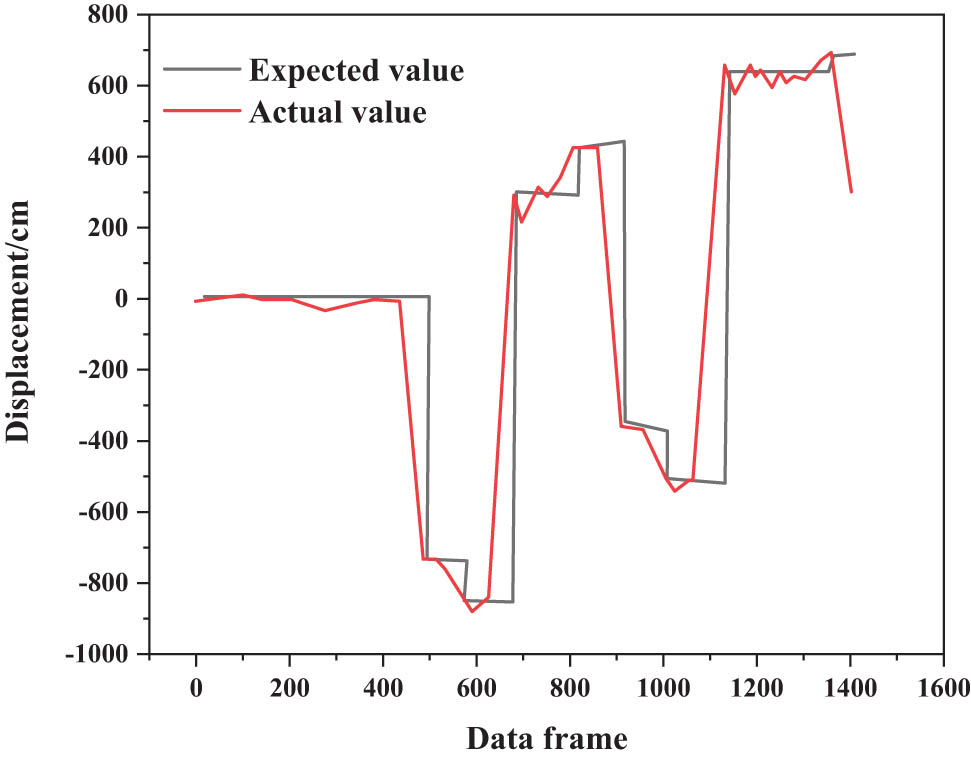
Northward position deviation.
In the following formula, TP is the true positive indicates the number of positive samples, which is also determined as the number of positive samples; TN is the true negative, indicating the number of negative samples, which are also judged as negative samples; FP is false positive, indicating the number of negative samples but judged as positive samples; FN is false negative, indicating the number of positive samples but judged as negative samples [16]. The accuracy rate, the accuracy rate, and the recall rate are shown in the formulas (7)–(9):
According to the accuracy rates of the five crack target detection algorithms in the crack database in Table 1, the highest accuracy rates of the five algorithms in the crack database are Canny, Faster R.CNN, LBP + HOG + BP, LBP + BP, HOG + BP. Their accuracy–recall curve is shown in Figure 5.
Crack target test results
| Crack target detection algorithm | Accuracy rate (crack) |
|---|---|
| LBP + BP | 0.9225 |
| HOG + BP | 0.9020 |
| LBP + HOG + BP | 0.9385 |
| Faster R-CNN | 0.9560 |
| Canny | 0.9688 |
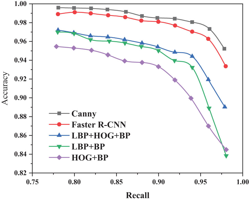
Precision rate of different types of crack target detection algorithms.
Figure 5 shows the accuracy and recall curves of several different types of crack target detection algorithms on the crack database. According to the accuracy and accuracy recall curve obtained by the aforementioned five methods, it can be clearly seen that the accuracy of Canny’s method is 96.88%. The Canny-based crack target detection method is trained and tested on the crack data set to obtain the classification results and the best detection effect. At the stage of large-scale wall crack image detection, Canny’s method was finally decided to complete the crack detection [17,18,19].
5 Conclusion
The author introduces and designs a building surface crack image acquisition and processing system based on STM32, and analyzes in detail the structure scheme of the aircraft and the digital image processing scheme of the ground station. The crack image is processed by digital image processing through image acquisition by aircraft. The classic SFC combination method is improved by introducing the adaptive filtering method, which simplifies the processing steps and improves the adaptability of the preprocessing algorithm to different types of building surface environments. The experimental results show that the Canny method achieves 96.88% accuracy in the test. The Canny-based crack target detection method is trained and tested on the crack data set to obtain the classification results and the best detection effect. At the stage of large-scale wall crack image detection, Canny’s method was finally decided to complete the crack detection. Through the comparison of five methods, Canny will be selected for crack detection and location in the crack detection and location stage of the research on building surface crack detection technology based on UAV images by the author. For some targets of misdetection, it is difficult to eliminate objects such as socket lines by only using geometric parameters. In this link, other feature information such as texture can be considered, and the effect of screening should be improved more, which can be further studied. The number of training samples used in training the crack detector model is not enough. The next step is to use the existing crack samples.
-
Funding information: This study did not receive any funding in any form.
-
Author contributions: Each author has made significant personal contributions to this manuscript. Yue Gao: writing and performing surgeries; Yuqing Liu: data analysis and performing surgeries; Fengjuan Guo and Xiangyu Jia: article review and intellectual concept of the article.
-
Conflict of interest: The authors declare that they have no competing interest.
-
Informed consent: Informed consent was obtained from all individuals included in this study.
-
Ethical approval: The conducted research is not related to either human or animals use.
-
Data availability statement: The data used to support the findings of this study are available from the corresponding author upon request.
References
[1] Y. Guo, Y. Lu, Y. Guo, R. W. Liu, and K. T. Chui, “Intelligent vision-enabled detection of water-surface targets for video surveillance in maritime transportation,” Hindawi Ltd., vol. 47, no. 8, pp. 707–716, 2021.10.1155/2021/9470895Search in Google Scholar
[2] H. Fan, S. Gao, Q. Liu, N. Ma, X. Zhang, and X. Cao, “Intelligent wear debris identification of gearbox based on virtual ferrographic images and two-level transfer learning,” Int. J. Pattern Recognit. Artif. Intell., vol. 32, no. 2–4, pp. 1–16, 2022.Search in Google Scholar
[3] G. Sun, X. Tao, N. Li, and J. Xu, “Intelligent reflecting surface and UAV assisted secrecy communication in millimeter-wave networks,” IEEE Trans. Veh. Technol., vol. 138, no. 8, pp. 8–15, 2021.Search in Google Scholar
[4] S. Geng, W. Zhang, S. Tian, Y. Zi, J. Miao, and R. Shen, “Study on UAV image extraction of surface crack information technology in goaf,” Open. Access. Library J., vol. 1302, no. 9, p. 042033, 2022.Search in Google Scholar
[5] B. Zhang, X. Qian, R. Yang, and Z. Xu, “Water surface target detection based on improved YOLOv3 in UAV images,” ICCBN 2021: 2021 9th International Conference on Communications and Broadband Networking, vol. 19, no. 19, 2021, p. 4115.10.1145/3456415.3456424Search in Google Scholar
[6] K. Chen, G. Reichard, X. Xu, and A. Akanmu, “Automated crack segmentation in close-range building faade inspection images using deep learning techniques,” J. Build. Eng., vol. 94, no. 3, pp. 398–406, 2021.10.1016/j.jobe.2021.102913Search in Google Scholar
[7] X. W. Gao, S. Li, B. Y. Jin, M. Hu, and W. Ding, “Intelligent crack damage detection system in shield tunnel using combination of retinanet and optimal adaptive selection,” J. Intell. Fuzzy Syst.: Appl. Eng. Technol., vol. 40, no. 3, p. 2787, 2021.10.3233/JIFS-201296Search in Google Scholar
[8] D. Dan and Q. Dan, “Automatic recognition of surface cracks in bridges based on 2D-APES and mobile machine vision,” Measurement, vol. 168, no. 6, p. 108429, 2021.10.1016/j.measurement.2020.108429Search in Google Scholar
[9] D. Choi, W. Bell, D. Kim, and J. Kim, “Uav-driven structural crack detection and location determination using convolutional neural networks,” Sensors, vol. 21, no. 8, p. 2650, 2021.10.3390/s21082650Search in Google Scholar PubMed PubMed Central
[10] X. Ni, H. Liu, Z. Ma, C. Wang, and J. Liu, “Detection for rail surface defects via partitioned edge feature,” IEEE Trans. Intell. Transport. Syst., vol. 99, pp. 1–17, 2021.Search in Google Scholar
[11] V. M. Nuzhdin, A. E. Ananenkov, and D. V. Marin, “Radar of complex UAV detection and neutralization,” 2021 Systems of Signals Generating and Processing in the Field of on Board Communications, vol. 12, no. 18, 2021, p. 3035.10.1109/IEEECONF51389.2021.9416133Search in Google Scholar
[12] H. Feng, S. Jie, M. Hang, R. Wang, F. Fang, and G. Zhang, “A novel framework on intelligent detection for module defects of PV plant combining the visible and infrared images,” Sol. Energy, vol. 236, no. 9, pp. 45–49, 2022.10.1016/j.solener.2022.03.018Search in Google Scholar
[13] M. Wei, J. Tang, H. Tang, R. Zhao, and R. Lin, “Adoption of convolutional neural network algorithm combined with augmented reality in building data visualization and intelligent detection,” Complexity, vol. 2021, no. 4, pp. 1–13, 2021.10.1155/2021/5161111Search in Google Scholar
[14] Y. Wu, G. Wan, L. Liu, Z. Wei, and S. Wang, “Intelligent crater detection on planetary surface using convolutional neural network,” IEEE, vol. 12, no. 2, p. 325, 2021.Search in Google Scholar
[15] X. Cui, Q. Wang, J. Dai, S. Li, C. Xie, and J. Wang, “Pixel-level intelligent recognition of concrete cracks based on DRACNN,” Mater. Lett., vol. 306, no. 2, p. 130867, 2022.10.1016/j.matlet.2021.130867Search in Google Scholar
[16] N. Patil, D. Shahare, S. Hanwate, P. Bagde, and M. Titre, “Designing of improved monitoring system for crack detection on railway tracks,” 2021 Third International Conference on Intelligent Communication Technologies and Virtual Mobile Networks (ICICV), vol. 57, no. 12, 2021, pp. 9524–9533.10.1109/ICICV50876.2021.9388429Search in Google Scholar
[17] P. Miao and T. Srimahachota, “Cost-effective system for detection and quantification of concrete surface cracks by combination of convolutional neural network and image processing techniques,” Constr. Build. Mater., vol. 293, no. 3, p. 123549, 2021.10.1016/j.conbuildmat.2021.123549Search in Google Scholar
[18] V. Uchanin, “Enhanced eddy current techniques for detection of surface-breaking cracks in aircraft structures”, Trans. Aerosp. Res., vol. 2021, no. 1, pp. 1–14, 2021.10.2478/tar-2021-0001Search in Google Scholar
[19] M. E. Hatır, İ. İnce, and M. Korkanç, “Intelligent detection of deterioration in cultural stone heritage,” J. Build. Eng., vol. 44, no. 12, p. 102690, 2021.10.1016/j.jobe.2021.102690Search in Google Scholar
© 2023 the author(s), published by De Gruyter
This work is licensed under the Creative Commons Attribution 4.0 International License.
Articles in the same Issue
- Regular Article
- The role of prior exposure in the likelihood of adopting the Intentional Stance toward a humanoid robot
- Review Articles
- Robot-assisted therapy for upper limb impairments in cerebral palsy: A scoping review and suggestions for future research
- Is integrating video into tech-based patient education effective for improving medication adherence? – A review
- Special Issue: Recent Advancements in the Role of Robotics in Smart Industries and Manufacturing Units - Part II
- Adoption of IoT-based healthcare devices: An empirical study of end consumers in an emerging economy
- Early prediction of cardiovascular disease using artificial neural network
- IoT-Fog-enabled robotics-based robust classification of hazy and normal season agricultural images for weed detection
- Application of vibration compensation based on image processing in track displacement monitoring
- Control optimization of taper interference coupling system for large piston compressor in the smart industries
- Vibration and control optimization of pressure reducer based on genetic algorithm
- Real-time image defect detection system of cloth digital printing machine
- Ultra-low latency communication technology for Augmented Reality application in mobile periphery computing
- Improved GA-PSO algorithm for feature extraction of rolling bearing vibration signal
- COVID bell – A smart doorbell solution for prevention of COVID-19
- Mechanical equipment fault diagnosis based on wireless sensor network data fusion technology
- Deep auto-encoder network for mechanical fault diagnosis of high-voltage circuit breaker operating mechanism
- Control strategy for plug-in electric vehicles with a combination of battery and supercapacitors
- Reconfigurable intelligent surface with 6G for industrial revolution: Potential applications and research challenges
- Hybrid controller-based solar-fuel cell-integrated UPQC for enrichment of power quality
- Power quality enhancement of solar–wind grid connected system employing genetic-based ANFIS controller
- Hybrid optimization to enhance power system reliability using GA, GWO, and PSO
- Digital healthcare: A topical and futuristic review of technological and robotic revolution
- Artificial neural network-based prediction assessment of wire electric discharge machining parameters for smart manufacturing
- Path reader and intelligent lane navigator by autonomous vehicle
- Roboethics - Part III
- Discrimination against robots: Discussing the ethics of social interactions and who is harmed
- Special Issue: Humanoid Robots and Human-Robot Interaction in the Age of 5G and Beyond - Part I
- Visual element recognition based on profile coefficient and image processing technology
- Application of big data technology in electromechanical operation and maintenance intelligent platform
- UAV image and intelligent detection of building surface cracks
- Industrial robot simulation manufacturing based on big data and virtual reality technology