
Recent developments in tensile properties of friction welding of carbon fiber-reinforced composite: A review
-
Mohammed Asmael
 ,
Omer Kalaf
,
Omer Kalaf

Abstract
In this review article, the joining of carbon fiber-reinforced polymer composite with metallic materials by using friction welding techniques was discussed and the effects of process parameters on the weld properties were evaluated. Major parameters involved in this process were plunge depth (PD), dwell time, joining time, and tool rotational speed. A successful friction joint of carbon fiber-reinforced poly composite laminate (CF-PPS)-metal was formed with an interlayer film of additional polyphenylene sulfide. In addition, a detailed overview of the friction techniques was discussed, such as friction stir spot welding (FSSW), friction stir welding (FSW), and refill friction stir spot welding (RFSSW). In this current work, we had focused on the parameters, process, and their development during friction welding of similar and dissimilar metals with CFRP joint. Regarding the FSSW review, the best tensile shear load was 7.1 kN obtained from AA5182 and CFRP at a rotational speed of 3,000 rpm and 5 s welding time. The thickness for AA5182 and CFRP are 1.2 and 3 mm, respectively. The most efficient parameters are rotational speed, PD, dwell time, and shoulder penetration depth. In addition, the heat generated during the process parameters, its influence on mechanical and microstructure properties along with the possible defects and internal cracks of the similar and dissimilar welded joints will be reviewed and discussed.
List of abbreviations
- AZ
-
adhesion zone
- CF-PPS
-
carbon fiber-polyphenylene sulfide
- CFRP
-
carbon fiber-reinforced polymer
- FSW
-
friction stir welding
- FSSW
-
friction stir spot welding
- FW
-
friction welding
- HAZ
-
heat affected zone
- JP
-
joining pressure
- JT
-
joining time
- PD
-
plunge depth
- PDZ
-
plastically deformed zone
- PRZ
-
pin refilling zone
- RFSSW
-
refill friction stir spot welding
- RSW
-
resistance spot welding
- SCF/PEEK
-
short carbon fiber polyether ether ketone
- SEM
-
scanning electron microscope
- SSZ
-
sleeve stirring zone
- SZ
-
stirring zone
- T m
-
melting temperature
- TZ
-
transition zone
1 Introduction
Carbon fiber-reinforced polymer (CFRP) composite materials are finding increased applications in many areas. They are strong, light, and have a usage in aerospace as well as in automotive industry, where high strength-to-weight ratios are required. Composite materials considered are very attractive in this industry, due to their high strength, density to stiffness ratio, and excellent physical characteristics. CFRPs class of composite materials are getting more interest in lightweight structures [1,2,3,4,5]. Plastics and metals have a huge difference in chemical and physical properties, thus obtaining bonding between metal and plastic materials is more difficult [6,7]. Although the use of various materials is beneficial in different structures, establishing a joint between dissimilar materials such as composites and metal alloys is a difficult task [8,9,10,11] due to their different physicochemical properties [12,13,14,15,16]. Because of their excellent electrical, thermal, and mechanical properties, CFRPs are commonly applied in the fabrication of polymer–matrix composites [11,17,18,19,20]. Therefore, extensive research has been performed on the application of conventional pitch-based CFRP in improving and optimizing the characteristics of a wide variety of structures [21,22,23,24]. CFRP industry is developing by the constant growth of demand from defense and aerospace as well as small markets such as construction materials and sporting goods [24,25,26,27]. In terms of manufacturing composite/metal structures, stack-up construction is an effective joining method. It poses a huge capital cost in structural completion in terms of labor intensiveness [28,29,30,31]. Friction welding (FW) is a joining method for solid materials, which creates material coalescence under compressive force when work pieces are moved or rotated relative to each other [32,33], producing heat and plastically displacing material from faying interface [34,35]. The welded joint has a narrow heat-affected zone (HAZ) [36,37], due to high temperature and pressure during the process, material show plastic deformation in the absence of a fusion zone [38,39]. In the last few decades, FW has been considered a major development in joining materials and has been applied in shipbuilding, high speed rail, aerospace, and automotive industries [40,41].
The state-of-the-art welding techniques for polymers such as laser and ultrasonic welding are consolidated technologies. However, their applications are restricted to certain types of polymers. The FW technique has many advantages over other available joining techniques, including low power consumption, short welding time with high mechanical performance, and low peak temperature and plastic deformation [42]. Liu et al. [43] studied FW, that only has a rotational shoulder, to join monomer casting nylon (MC Nylon-6) and 6061-T6 Al alloy. Ratanathavorn and Melander [44] applied FW to join AA6111 and poly-phenylene-sulfide (PPS) at the upper and lower sides. They stated that mechanical interlocking attributes to tensile shear properties.
In many industrial applications, such as wind power towers [45,46], bridge construction [47,48], and in transportation [49,50], lightweight structures are becoming highly popular [51,52]. Aluminum (Al) has a long and successful history of application in the designing, assembling, fabricating, and recycling of different structures with constant growth [53,54,55], as shown in Figure 1. Currently, numerous well-known automotive companies use this material. Also, other industries such as trim and cosmetic pieces which are available in the aftermarket as well as underbody structures, A-pillars, spoilers, drive shafts, various body panels, and other low-volume, high-performance cars use this material [56,57].
![Figure 1
Application of CFRP can reduce body weight by 30% [58].](/document/doi/10.1515/ntrev-2022-0083/asset/graphic/j_ntrev-2022-0083_fig_001.jpg)
Application of CFRP can reduce body weight by 30% [58].
The application of composite materials in commercial aircraft has become attractive since they reduce the weight of the airframe decreasing fuel consumption and therefore, operation cost [59]. Hereby composite materials accounting for about 50% of the material used in the production of the Boeing 787 can reduce its average weight by 20%. Composite materials are applied in key structural components of several modern helicopters, in which composites comprise about 50% of the total weight as shown in Figure 2. The formability property of the composite materials has been employed in helicopter manufacturing to decrease the number of components and consequently cost [60,61].
![Figure 2
The AIRBUS A380 aircraft composite applications [62].](/document/doi/10.1515/ntrev-2022-0083/asset/graphic/j_ntrev-2022-0083_fig_002.jpg)
The AIRBUS A380 aircraft composite applications [62].
Friction heating has been applied in thermoplastic matrix localized melting [63,64,65,66]. The abovementioned thermal method depends on matrix material partial melting within CFRPs, resulting in the interlocking and bonding of adhesive to the surface of the metal [67,68,69,70]. Several researchers have studied different splicing techniques of metal and plastic materials such as ultrasonic spot welding (USW) [71,72] and FW [73,74]. Generally, mechanical fastening and adhesive bonding [74,75,76] are the most commonly applied approaches for joining metals and plastic materials [77,78,79]. Mechanical fasteners increase the weight of a structure and create stress concentration, while the joint fabricated with adhesive bonding requires high surface pretreatment and longer curve times are additional drawbacks [80,81]. Commonly used approaches for joining metals and carbon fiber-reinforced polymers CFRPs, such as adhesive bonding, riveting, bolting, etc., are non-thermal processes while welding is a thermal process [82,83,84]. Few research works have been performed on joining matrix composites and metal. However, in some studies, friction stir spot welding (FSSW) has been employed to form an in-situ metal matrix composite during welding [85,86]. Normally, polymer materials are joined by adhesives or fasteners. The thermoplastic (plastic polymer) or composite could be successfully joined with metals by FW and achieve the best results [87,88,89]. However, conventional FSSW provides a convenient and fast alternative for these methods [90] and has been applied to join polypropylene, dissimilar polymethyl, high-density polyethylene [91,92], and methacrylate [93] to acrylonitrile butadiene sheets [94]. In recent years, refill friction stir spot welding (RFSSW) has also been employed to join polymethyl-methacrylate plates and strengths similar to ultrasonic welding or adhesively bonded areas were achieved [95,96]. The aim of this article is to focus on the tensile properties of FW such as FSSW, RFSSW, and friction stir welding (FSW) and also present joints of CFRP with metal and non-metal in different welding processes. Metals and non-metals are different types of materials present around us. Elements can be divided into metals and non-metals and it is important to know whether a particular element is a metal or non-metal. Metals (like copper and Al) are good conductors of heat and electricity, while non-metals (such as phosphorus and sulfur) are insulators. Materials are distinguished as above, based on their properties. The main purpose of this review article is to highlight the latest possible joining methods which can be reliable to join CFRP with metals, instead of fasteners and adhesive bonding which cause serious issue and increase extensive weights in structure. FW is a good alternative joining method that can help to weld dissimilar metals without melting any material to create a sound weld joint. This article is organized as follows: Section 1 provides a brief introduction and application of FW. In Section 2, we outline the classification of FSSW and its application and recent progress in this field. In Section 3, RFSSW and its tabular comparison with FSSW are presented. In Section 4, FSW is described and the last section provides the summery about all FW techniques and highlights the significant parameters that affect the strength of weld joint.
2 Methodology
In this review article, the database of articles was collected from different reliable sources like ScienceDirect, Google Scholar, and Scopus. The main sources of articles were Scopus. The articles were searched according to the keywords “friction stir spot welding; refill friction stir spot welding; and friction stir welding, with carbon fiber.” The articles published with the keyword of friction stir spot welding were 61. Similarly, the articles published on Scopus with the keyword of refill friction stir spot welding were 12. The total collected articles under the keyword of friction stir welding were 327, published from 2010 to 2022 as shown in Figure 3. Generally, these documents included research papers of more than 70%, conference papers from 5 to 11%, and review papers of about 10%.
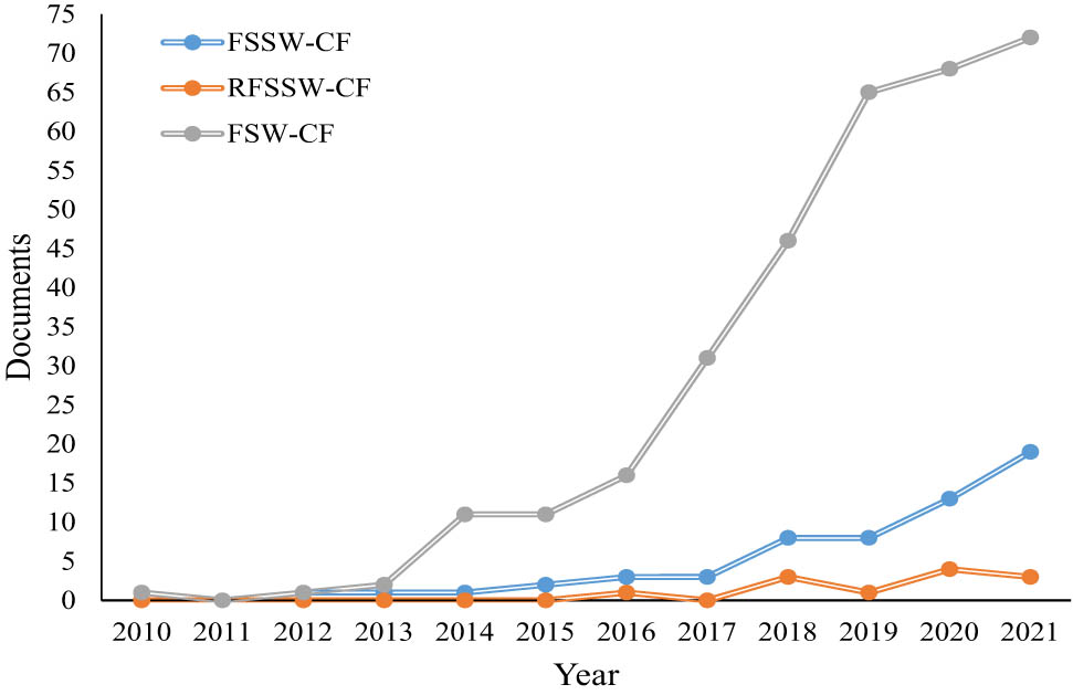
Published documents per year with keywords “friction stir spot welding, refill friction stir spot welding, and friction stir welding with carbon fiber.”
3 FSSW of CFRP
Generally, FSSWs are formed by the retraction of a rotating tool and plunging into and out of the materials to be joined. A keyhole is formed at the end product which is generated by this approach [10,97,98]. FSSW usually takes 2–5 s and during this short time, heat formation in the sheathing case and flipping region links the contacting plates. The energy density created by tool rotation is very high during spot welding [99,100,101]. FSSW uses a non-consumable tool and generates heat by friction. The tool consists of a sleeve clamping ring and pin which move relative to each other independently and collectively axially [102]. In FSSW, heat is needed and is generated between work pieces and parts. The rotation between sleeve and pin is independent and the parts being joined are held with the ring [103,104]. The rotating sleeve is plunged into the work piece to a predetermined depth while the pin rises. Temperature increases due to the friction between the sleeve and work piece to locally plasticize as shown in Figure 4. Then, the molten layer consolidates under pressure inducing adhesion and snarl between materials and composites [105,106]. Unlike FSW, in FSSW, the tool is plunged up to 40% of the thickness of metal and does not reach composites [107].
![Figure 4
Schematic diagram of FSSW process [108].](/document/doi/10.1515/ntrev-2022-0083/asset/graphic/j_ntrev-2022-0083_fig_004.jpg)
Schematic diagram of FSSW process [108].
The key factor in the generation of heat is tool rotation [109,110], because tool torque is responsible for almost the total energy generated in FSSW [111,112], which also controls material stirring around the tool. The torque of the tool is also responsible for heat generation and thermal cycle [113] and the increase in rotation rate increases temperature resulting in higher mixing intensity of the materials. This additional energy input directly relates to weld strength and bonded area [98,114,115]. Sheet thickness and pin length determine tool penetration depth into the contact sheets, which are the most effective factors in weld strength and bond dimensions. The macrostructure of the FSSW weld is highly related to the depth of the shoulder plunge. By the increase in the depth of shoulder plunge, the stirring zone is expanded and material flows upward from the lower sheet [116]. The shoulder penetration has to be deep enough to guarantee horizontal alignment of the interface tip to avoid fracture by the interfacial fracture [117]. However, the tensile shear load is bilaterally affected by the depth of shoulder penetration; a great amount of material is extruded from the top sheet when exposed to excessive shoulder penetration, resulting in excessive top sheet thinning, creating upward bending, and gap formation between the sheets [118,119]. Therefore, 0.2 mm shoulder penetration is generally applied in conventional FSSW [120,121].
In conventional FSSW, heat generation by the shoulder of the tool is somehow low unless a dwell period is used. During the dwell period, shoulder contribution in the generation of heat and flow of material is significantly enhanced such that the highest fraction of energy generation takes place during this period [109]. Nasir et al. [122] studied the effect of welding parameters (rotational speed (RS) and dwell time) on the microstructure and mechanical performance of dissimilar AA5754 and AA7075-T651 by FSSW. RS and dwell time vary in the ranges of 1,000–1,400 rpm, and 2–5 s, respectively. The maximum tensile shear force was 806.3 N at 1,000 rpm and 2 s dwell time. The material becomes soft at 1,400 rpm compared to a lower speed of 1,000 rpm. In addition, dissimilar intermixing does not take place in spot welds formed by a threaded tool with no dwell period. The reason for getting high strength at low RS and dwell time is the generation of low heat input. While high RS and high dwell time lead to high heat input which causes a raise in the grain size that decreases the joint strength [97,123]. Moreover, the addition of dwell periods extends the spot welding cycle which could be an important issue when the completion time of the target weld has to be less than or equal to that of resistance spot welding (RSW). In pinless FW, a much greater direct contact area is made between the material and shoulder, enhancing the flow of the material and significantly increasing the temperature when applying a short dwell time [124,125]. Such fast welding cycles (<1 s) cause less HAZ softening in heat-treatable Al alloys [126,127,128]. The mechanism of heat generation during FSSW differs from that in linear FSW because FSSW is a very transient joining process [129]. In pinless FSSW, generally a shoulder with a diameter of 10 mm is applied [130,131,132].
The results obtained from numerical simulations reveal that sleeves with greater outer diameters greatly increase the flow velocity, heat input, and welding spot area where a sleeve of 9.0 mm in diameter was most commonly applied in RFSSW [133,134,135,136,137,138]. In the comparison between adhesion bonding joints and FSSW, the results show that there is no significant use of adhesions instead of FSSW, also the mechanical performance of FSSW was higher than adhesive joint [139,140]. Goushegir et al. [105] studied the process parameters on mechanical performance and bonding area of aluminum Carbon fiber-polyphenylene sulfide (CF-PPS) and Al alloy AA2024-T3 with rotating speed of 1,900–2,900 rpm. Plunge depth (PD) was in the range of 0.5–0.8 mm and the obtained results revealed that tool PD significantly affected lap shear force. The PD of the tool into the Al is also statistically significant when analyzing ultimate lap shear force ULSF as the response. The PD influences the shape of the metallic nub and therefore thermo-mechanical interlocking takes place between the Al and the composite. The formation of the metallic nub and its insertion into the composite leads to the increased macro-mechanical interlocking and strength of the joints, especially under shear loading as shown in Figure 5.
![Figure 5
(a) and (b) shows the cross-sectional images of the joints inside the plastically deformed zone with RS of 2,900 rpm and joining pressure 0.2 and 0.3 MPa, respectively [105].](/document/doi/10.1515/ntrev-2022-0083/asset/graphic/j_ntrev-2022-0083_fig_005.jpg)
(a) and (b) shows the cross-sectional images of the joints inside the plastically deformed zone with RS of 2,900 rpm and joining pressure 0.2 and 0.3 MPa, respectively [105].
A larger metallic nub increases the macro-mechanical interlocking. Joining time is also an important parameter; when time is short, the molten PPS has low viscosity, therefore to enhance the flow of molten PPS, a high PD and lap shear force varying in the range of 1,698–2,310 N are required. Increasing RS, PD, and joining pressure (JP) increases the lap shear force, whereas increasing the joining time reduces the lap shear force. The comparison between the influence of process parameters on the responses shows that RS and JP significantly influence both the plastically deformed zone area and the lap shear force. During the process of FW, temperature varies in the range of 370–474°C. The temperature in each condition was high enough to allow the deformation of Al under the tool and the formation of the metallic nub. The rate of cooling and heating in this study were 17 and 97°C/s, respectively, which is very fast. Andre et al. [141] investigated the effects of rotating speed and joining pressure on the mechanical strength and microstructure of friction spot welding of CFRP and Al alloy AA2024-T3 with 100 µm PPS film interlayer. JP and RS vary in the ranges of 0.2–0.3 MPa and 1,900–2,900 rpm, respectively. They reported that lap shear force increased from 2,700 to 3,070 N, which was higher than those for joints without interlayers because of their improved micromechanical interlocking, better load distribution, and larger bonding area. Furthermore, compared to the joints without an interlayer, an increase in ultimate lap shear force by 55% was observed in this work for the joints with additional interlayer produced with low heat input conditions. In the case of the high heat input condition, an average improvement of 20% was reached. The temperature was measured on the top surface of a work piece, temperature varies in the range from 325 to 417°C. In the microstructure of interfaces, two bondings were found, the PPS into the crevices of Al and CFRP entrapment by Al deformed as shown in Figure 6. Furthermore, the peak temperatures were above the melting point of the PPS matrix of the CF-PPS and the PPS film (T m = 280°C). Therefore, the PPS film and a thin layer of the PPS matrix of the CF-PPS composite were melted and recrystallized during the friction stir joint process.
![Figure 6
Microstructural details of joint: (a) cross-section with interlayer, (b) molten polymer of Al surface, (c) deformed aluminum, and (d) interface of Al/interlayer [141].](/document/doi/10.1515/ntrev-2022-0083/asset/graphic/j_ntrev-2022-0083_fig_006.jpg)
Microstructural details of joint: (a) cross-section with interlayer, (b) molten polymer of Al surface, (c) deformed aluminum, and (d) interface of Al/interlayer [141].
Goushegir et al. [142] applied Al alloy A2024-T3 and carbon fiber poly(phenylene sulfide) CF-PPS as test specimens, presented friction spot welding of single lap joint, and evaluated the obtained joint results based on their microstructure and mechanical performance. In this study, PD and joining time were fixed at 0.5 mm and 4.8 s, respectively. RS was increased from 1,900–2,900 rpm. The highest rotation speed obtained for the optimum value of shear force was around 1,254 N. Increase in joining area resulted in more intimate contact between PPS matrix and CFRP with Al and hence better mechanical performance. This also increased tool PD and joining time. The influence of increasing PD on lap shear force and displacement at the peak load of joints (762.6 ± 182.7 N/0.45 ± 0.08 mm for PD of 0.5 mm and 1,276 ± 181.5 N/0.65 ± 0.05 mm for PD of 0.8 mm). This trend is associated with the generation of a more pronounced “nub” and increased intimate contact at the composite/Al interface, which can increase adhesion forces by micromechanical interlocking. Joining time and RS increase heat generation and change microstructure and lap shear strength, while intermediate RS and longer joining time lead to greater consolidated polymeric layers at the metal/composite interface. Molten PPS matrix fills these pores/crevices, which, after consolidation, increases the micro-mechanical interlocking and global shear strength of the joint. Another important phenomenon is also observed: a portion of CFRP is entrapped by plasticized Al, thereby creating a micro-mechanical interlocking. Esteves et al. [102] studied the effects of different parameters on the mechanical strength and microstructure of CF-PPS and Al alloy AA6181-T4 joined by friction spot welding. In this study, the rotating speed was increased from 1,200 to 1,600 rpm. The maximum shear force was 3,523 N with a RS of 1,200 rpm, PD of 1.15 mm, and joining time of 6 s. Higher heat input induces the formation of large bonded areas, as visually confirmed by a large amount of PPS molten layer at the interface. This can be seen in fracture surfaces. Moreover, pronounced nub formation was observed due to the large heat input. Increase in joining time and rotating speed directly increased heat generation and changed lap shear strength and microstructure. Heat input is responsible for PPS molten layer in the joint interface increasing the bonding area. Moreover, PD plays an important role in macro-mechanical interlocking mechanisms at the metal/composite interface controlling the formation of the metallic nub. The higher the PD the more pronounced the metallic nub will be, as shown in Figure 7.
![Figure 7
Cross section micrographs from top and mid views in different plunge depths: (a) 0.75 mm, (b) 1.0 mm, (c) 1.15 mm, and (d) 1.25 mm [102].](/document/doi/10.1515/ntrev-2022-0083/asset/graphic/j_ntrev-2022-0083_fig_007.jpg)
Cross section micrographs from top and mid views in different plunge depths: (a) 0.75 mm, (b) 1.0 mm, (c) 1.15 mm, and (d) 1.25 mm [102].
Andre et al. [143] evaluated the mechanical performance of Al alloy AA7075-T6 and CFRP by FSSW. In this study, rotating speed, joining time, and PD were 1,900 rpm, 4 s, and 0.8 mm, respectively, and joining force was varied from 4 to 8 kN. The obtained result showed that lap shear force was 4,068 N and joining force significantly affected nub geometry at 6 kN. It is worth noting that, for all the investigated joints, a layer of the reconsolidated molten PPS was formed and remained attached to the Al surface providing adhesion forces. Additionally, signs of fiber and matrix entrapment on the Al surface were observed in all cases. It is possible to note that an effective micro-mechanical interlocking was achieved because PPS matrix took the shape of the irregularities of the Al surface, while some fibers were entrapped into crevices. The maximum temperature on the Al surface was 331°C. The bonding area was divided into various zones, namely adhesion zone (AZ), transition zone (TZ), and plastically deformed zone (PDZ), as shown in Figure 8. These zones were formed during the welding process and air bubbles were formed when the molten matrix moved from the center to the edge of the joint.
![Figure 8
SEM image: (a) transition between AZ and TZ, (b) PDZ of Al surface, (c) PDZ, and (d) TZ on the composite surface [143].](/document/doi/10.1515/ntrev-2022-0083/asset/graphic/j_ntrev-2022-0083_fig_008.jpg)
SEM image: (a) transition between AZ and TZ, (b) PDZ of Al surface, (c) PDZ, and (d) TZ on the composite surface [143].
Andre et al. [107] studied the mechanical performance and microstructure of CFRP and Al alloy AA2024-T3 joints formed by FSSW with an additional PPS film interlayer. Rotating speed was varied from 1,300 to 2,500 rpm. The optimal tensile shear force of about 2,000 N was obtained at 1,900 rpm rotating speed, 0.8 mm PD, and 6 s joining time, and showed linear elasticity before the final catastrophic failure. The PD of the sleeve is also a very important process parameter because it is directly related to nub formation and its final geometry, mechanical interlocking between the joining partners and consequently to the joint strength. A high RS of 2,500 rpm resulted in an accentuated decrease in molten viscosity supporting the squeezing of the molten interlayer outside the metallic nub area. The area around the nub cohesive failure dominates the polymer matrix and the remaining CFRP will be attached to the Al. In this study, the influence parameters show the effect of PD on the lap shear force. Manente André et al. [144] improved the adhesion mechanisms and mechanical performance of Al alloy AA2024-T3 and CFRP with additional 100 µm PPS film interlayer FSW. In this study, RS, PD, and joining time were 1,900 rpm, 0.8 mm, and 4 s, respectively. The optimal tensile shear force was 3,068 N obtained at a high roughness effect on contact surface area. Also, sandblasting was found to be the most effective treatment which maximized the performance of mechanical joint. Increase in roughness creates crevices on the surface and enlarges effective contact area, contributing to micro-mechanical interlocking and establishing adhesion forces. Impressions containing pieces of CFRP removed from PPS matrix were identified on interlayer fracture surface after lap shear testing. This is an indication of an effective micro-mechanical interlocking at the interface of interlayer composite achieved with sandblasted specimens.
Andre et al. [145] studied the influence of PPS film interlayers with different thicknesses on the mechanical performance and microstructure of Al alloy AA2024-T3 and carbon fiber CF-PPS by friction spot welding. In this work, rotating speed, PD, and joining time were 1,900 rpm, 0.8 mm, and 4 s, respectively, and 2 different interlayer thicknesses of 100 and 500 µm were investigated. The results showed that the maximum temperature was 360°C in both cases. The volume of metal deformation was embedded slightly in CFRP during welding with 100 µm interlayer. On the other hand, with a 500 µm interlayer, the formation of the metallic nub arises through the embedding of the deformed metal in the interlayer film, without reaching the composite. Also, bubbles were trapped in polymer and resulted in the creation of cavities after the solidification of the welding joint. Maximum shear forces were 2,093 and 708 N in the case of 100 and 500 µm interlayers, respectively. The thinner 100 µm film was softened more efficiently than the thicker 500 µm film by the frictional heat generated during the joining process. Accordingly, although the Al/film interface had effective micro-anchoring for both joints, film/composite interface displayed greater cohesion for the joints with 100 µm thick film. More efficient softening of this interlayer film favors inter diffusion of the PPS chains of the matrix of composite and film. The film with lower thickness presented better results than the higher thickness interlayer.
Ogawa et al. [146] studied the effects of welding properties of FSSW of Al alloy AA5182 and CFRP. Tool rotating speed was 3,000 rpm and welding time was set to 1, 2, and 5 s. The results showed that temperature on Al surface varied from 200 to 250°C. Also, average static strength for 1, 2, and 5 s welding times were 4.1, 5.5, and 7.1 kN, respectively. Static strength was significantly improved by increasing welding time. Microstructural results showed that pores were formed on CFRP side which mainly concentrated under the tool center. Resin-based CFRP was melted just under tool periphery and a layer of resin was preserved between the two materials. As it has been observed that with increase in the dwell time, the joint strength increases due to the high heat input which increases the joint area and melts the resin as well. Goushegir [12] studied friction spot welding of CF-PPS and Al alloy AA2024-T3. Rotating speed, PD, and joining time were 2,900 rpm, 0.8 mm, and 4 s, respectively. The obtained results showed that temperature varied between 345 and 474°C. The temperature of approximately 400°C lies in the range of dynamic re-crystallization of AA2024 for friction-based joining processes. Microstructural zones were divided into different areas: polymer heat affected zone (PHAZ), heat affect zone (HAZ), thermo-mechanical affect zone (TMAZ), and stir zone (SZ). Different microhardness values were observed in different zones; in the base material (zone 1) average hardness was 135 HV, in the string zone, high microhardness of 151 HV was observed, the average hardness of TMAZ was 139 HV, and the lowest microhardness of 123 HV was witnessed in HAZ. Also, the average ultimate lap shear force was 8,264 N, while reference bonded was shown to be 5,459 N. This was explained by the fact that the primer was a carbon-based epoxy layer leading to the formation of very strong carbon–carbon primary bonds with PPS consolidated layer during joining cycle.
Ogawa et al. [147] studied FSSW of CFRP and Al alloy AA5182. The rotating speed was 3,000 rpm. It was confirmed that pores were present inside CFRP, irrespective of the treatment of the surface in the microstructure of the welding joint. These pores were assumed to be developed either by the air entrapped by molten resin flow or during CFRP molding which was then expanded because of frictional heat. The average static strengths of the untreated, porous layer and organic coating series were approximately 5.7, 6.6, and 7.4 kN, respectively. Hence, surface treatment was found to enhance FSSW joint static strength. The shoulder diameter was 10 mm and the probe length was 0.35 mm. Amancio-Filho et al. [148] studied the FSSW of magnesium AZ31 and carbon fiber-reinforced polymer. In their research, rotating speed was varied from 900 to 3,000 rpm, PD was in the range of 0.25–1.75 mm, and joining time was changed from 3 to 8 s. The results showed that on PPS-CF/AZ31 surface, the temperature was varied in the range of 400–440°C (1,500 rpm, 0.25 mm, and 8 s). SZ was characterized by fine dynamic recrystallized grains. In microstructure, the SZ showed that Mg17Al12 dispersed particles and could be observed. Although the bonding mechanisms of joint are not yet well understood, there are strong indications that joining is accomplished by a mixed regime of surface mechanical interlocking and adhesion between the metallic and consolidated polymeric layers, as well as direct partial fiber attachment on the metallic plate. A thin transition zone between the HAZ and SZ is called the TMAZ, as illustrated in Figure 9. Tensile shear force was 2,000 N in AZ31/PPS-GF but only 1,500 N in AZ31/PPS-CF.
![Figure 9
: Hardness and microstructure of AZ31 joint: (a) cross-section image pf microhardness and macrograph maps; (b) AZ31 base material upper region; (c) AZ31 volume below clamping ring; (d) transition details between SZ and TMAZ; (e) SZ center; (f) transition region of TMAZ and SZ; (g) heat affected zone central region; (h) polymer–metal interface within metallic nub; (i) consolidated polymer layer underneath metallic nub; (j) consolidated polymer layer close to metal–polymer interface, and (k) the upper portion of base material polymeric plate [148].](/document/doi/10.1515/ntrev-2022-0083/asset/graphic/j_ntrev-2022-0083_fig_009.jpg)
: Hardness and microstructure of AZ31 joint: (a) cross-section image pf microhardness and macrograph maps; (b) AZ31 base material upper region; (c) AZ31 volume below clamping ring; (d) transition details between SZ and TMAZ; (e) SZ center; (f) transition region of TMAZ and SZ; (g) heat affected zone central region; (h) polymer–metal interface within metallic nub; (i) consolidated polymer layer underneath metallic nub; (j) consolidated polymer layer close to metal–polymer interface, and (k) the upper portion of base material polymeric plate [148].
Goncalves et al. [149] studied FSSW of polyamide 66 laminate reinforced with CFRP. During the welding, the plunge was a depth of 2 mm and the rotation speed was 3,000 rpm. According to these parameters, the average strength of lap shear was 26.8 MPa from a nominal area of 63.6 mm2 in the external diameter of the sleeve. Mechanical and thermal effects were evident in the material around the sleeve. However, in their early stage of development, these welds showed comparable mechanical performance to similar joints produced with state-of-the-art welding technology reported in the literature. This region was called the SZ, as shown in Figure 10, which was mixed between polymer and broken CFRP.
![Figure 10
CF-PA66 weld microstructure produced by FSSW [149].](/document/doi/10.1515/ntrev-2022-0083/asset/graphic/j_ntrev-2022-0083_fig_010.jpg)
CF-PA66 weld microstructure produced by FSSW [149].
Huang et al. [150] studied carbon fiber polyetherimide laminate friction spot welding. In this study, PD was 2.2 mm, dwell time was 2 s, and rotating speed varied from 800 to 1,200 rpm. Welding tool was made of titanium alloy to reduce heat loss, which consisted of a clamping ring, sleeve, and pin. At low rotating speeds, thermoplastic materials cannot be softened completely. With the increase in the rotating speed, defects are reduced and appeared only at the border of the sleeve. Thickness reduction or unfelling defect appeared at the pin refilling zone (PRZ) on the joint surface. The microstructure in this joint was divided into a sleeve stirring zone (SSZ) and a thermo-mechanically affected zone. CFRP and polyetherimide laminate showed long circular fibers because of the stacking sequence. Meanwhile, the lower thermal conductivity of the polymer is difficult to make frictional heat conduct to the middle interface between the upper and lower sheets, and then the lack of adhesive joining forms. The length of no adhesive joining area was gradually decreased with the increase in the rotational velocity due to the improvement of thermo-mechanical behavior. Also, the maximum and minimum tensile shear forces were about 1,600 and 1,250 N at rotating speeds of 1,200 and 800 rpm, respectively. With increase in the rotational velocity to 1,000 rpm, the improvement of effective joining length benefited from joint strength compared with the rotational velocity of 800 rpm.
Goncalves et al. [151] studied the improvement of FW joining polyamide 6 and polyamide 66/carbon fiber laminate. There were two conditions in this work. Rotation speed and depth of penetration were fixed at 1,500 rpm and 3.8 mm, as conditions A and B, respectively. The diameter of clamping was 14.5 mm in condition A and 22 mm in condition B. The results showed that maximum temperatures were 280 and 352°C, respectively. Microstructure cross-section in condition A had a depth of 3.08 mm, while in condition B it was only 0.74 mm. The corresponding tensile shear forces were 1,323 and 2,196 N in condition B. The welding of thermoplastics by FW required larger thermal inputs during welding compared to metals, owing to the low thermal conductivity of polymers. If the larger thermal input of condition B was used with tool geometry optimized for welding metals, the tool would penetrate all the way through the specimen, making welding impossible. Bolouri et al. [152] studied a new design of joining Al alloy Al 1050 and CFRP with 50% fiber with FSSW. Rotating speed was varied in the range of 2,500–3,000 rpm and joining time and dwell time were 4 and 2 s, respectively. PDs were in the range of 0.8–1.0 mm and the average temperature was increased from 310 to 400°C by increasing the rotating speed from 2,500 to 3,000 rpm. Changes in the feed rate and PD of the pin affect the joining temperature. The joint between Al and CFRP was unsuccessful at PD of 0.75 mm. An increase in PD to 1.25 mm resulted in a successful joint. Also, an increase in PD from 1.25 to 1.30 mm enhanced lap shear strength from 230 to 241 N. Interlocking between Al and CFRP increased the performance of the joint and shear force showed brittle fracture in the joint. The hooks noticeably retained the CFRP attached with Al alloys, which increased the strength of joints. In addition, as a result of the creation of more pronounced nub and hooks, the intimate contact at the interface of Al alloy and CFRP was increased that could further push the molten resin to fill into the crevices on the surface of Al alloy.
Nasir et al. [153] successfully conducted experimental studies on CFRP as an interlayer in dissimilar AA7075-T651 and Ti-6A-4V alloys by FSSW at specified welding parameters (RS and dwell time) and investigated the mechanical and microstructural properties of welded joints. The obtained results showed that the mechanical performance of the weld joint was increased with the increase in RS. A maximum tensile shear load of 2,597.8 N was gained at a RS of 2,000 rpm and a high dwell time of 10 s. Dwell time had a significant effect on the mechanical properties and raised tensile shear load to 54.7% at a high RS. The hardness of the weld joint was increased by RS and 18.90% improvement was observed in the keyhole of a weld joint. One thing that has been noted with joints made with CFRP interlayer was that they had low tensile strength compared to metals without interlayer. On the other hand, at high RS and high dwell times without CFRP interlayer, low tensile strength was observed which was resolved in the case of CFRP interlayer with dissimilar metal alloys. Kalaf et al. [154] applied CFRP as an interlayer in similar Al alloy AA5052 to investigate the effects of welding parameters (RS and dwell time) on the mechanical properties, joint efficiency, and microstructure of the friction stir spot weld joint. The maximum tensile shear load of 1,779.6 N was obtained at 2,000 rpm and 2 s. A significant improvement in hardness (29%) was obtained in the key whole area at high RSs and high dwell times. The best tensile shear load was 7.1 kN obtained for AA5182 and CFRP by FSSW at RS of 3,000 rpm and welding time of 5 s; the thickness for AA5182 and CFRP were 1.2 and 3 mm, respectively. The joints were improved as the welding time was increased. This grain was affected by a larger welding area and increased resin melting. So, increasing welding time was effective in improving the joint strength.
4 RFSSW of CFRP
Researchers at Helmholtz-Zentrum Geesthacht (Germany) introduced and patented RFSSW in 1999 for joining two or more sheets made of lightweight materials like Al and Mg alloys [155]. Joint was prepared by plasticization and material displacement in a process similar to back extrusion. The most important advantage of RFSSW is the lack of keyhole structure in the weld where the weld is nominally flush with the original surface. According to Figure 11, the tool applied in RFSSW comprises an inner pin, a sleeve, and an outer stationary clamp ring. The clamping ring firmly held work pieces in contact throughout the welding and prevented the sheets from separating and lifting when plasticized material was displaced by sleeve and pin [156,157,158,159].
![Figure 11
Schematic diagram of RFSSW [164].](/document/doi/10.1515/ntrev-2022-0083/asset/graphic/j_ntrev-2022-0083_fig_011.jpg)
Schematic diagram of RFSSW [164].
Using one single motor, the pin and sleeve rotated at the same speed and along the same direction and were independently moved up and down by separate actuators. RFSSW process is more complicated than conventional FSSW and, depending on the plunging component, could be classified into sleeve plunge and pin plunge variants. A schematic diagram of the sleeve plunge variant is shown in Figure 11. First, the sleeve was plunged into the work piece to a previously calculated depth for material plasticization, while pin moved upward to form an accurate cylindrical cavity for the accommodation of the plasticized material squeezing out by sleeve. Once a certain dwell time was passed, pin and rotating sleeve returned to their original locations and extruded the softened materials into the joint creating a spot weld with zero or minimum surface indentation. The key advantage of sleeve plunge variant over pin plunge variant was its highly strong weld because of greater nugget size. However, this variant demanded higher plunge forces [157,160,161,162,163].
The refill method achieves overlap shear strength that compares favorably to self-piercing riveting, RSW, and conventional FSSW, with joining times almost similar to the latter [95,165]. Also, RFSSW has some advantages such as the ability to join lightweight materials including polymers and Mg and Al alloys [166] and dissimilar pairs such as polymers to metals [148] and ferrous metals [167,168,169] to non-ferrous metals [170,171]. RFSSW has been successfully applied in the fabrication of skin stiffened panels [172], filling of keyholes resulting from FSSW, rivet or fastener replacement, RSW replacement, repairing fatigue cracks, and as a tacking welding method for FSSW [173,174,175].
In RFSSW, the depth of plunge is more flexible and is defined as the PD of plunging element (either pin or sleeve). Pin lengths which do not reach bottom sheet, decrease the strength of spot weld tensile because the keyhole formed by pin decreases the cross section. When tool pin is penetrated into bottom sheet, it contributes to bond formation providing mechanical strength. At the RS of 2,000 rpm, the numerically obtained velocity field of the material just under tool pin is about 50% of that beneath the shoulder. It is noteworthy that the bottom of the pin has a certain distance from the bottom of the shoulder and therefore its contribution is remarkably enhanced. With the increase in pin length, its role in the total velocity field is increased. At a critical length, pin increases weld zone size and improves weld joint strength [176]. At pin lengths beyond the material flow zone formed by the shoulder, strength could be decreased because of excessive plunging resulting in the extrusion of a portion of the bottom sheet significantly decreasing the thickness of the bottom sheet under the pin [162,177,178,179].
Threads in RFSSW are generally machined on pin and sleeve to decrease the contamination of interfaces among three tool components [180]. Ji et al. [181] applied a 3D finite element model to study grooved sleeve effects on the flow of materials and concluded that grooved sleeves increased the velocity of material flow, and grooves on the inner walls of sleeves outperformed those with lower widths on the outer walls of sleeves. Scrolled grooves were more favorable than concentric circular grooves at the bottom of sleeves in decreasing the thickness of bonding ligament and increasing the area of bonding. Pabandi et al. [182] studied RFSSW of Al alloy AA5252 with short carbon fiber polypropylene (PP-SCF) and applied 500–2,000 rpm rotating speed and 5 s dwell time. A cylindrical tool from heat-treated H13 steel composed of a shoulder with a diameter of 20 mm was employed as the welding tool. They found that the optimal shear tensile was 350 N at 2,000 rpm and the maximum hardness was 68 HV obtained at 500 rpm, as shown in Figure 12. Temperature evaluation was performed at various distances from the center of the joint and the maximum value was found to be 340°C, 10 mm from the joint center. Scanning electron microscope (SEM) images showed 15 µm at the interface reaction layer and it seemed that the layer was formed by an erosion mechanism. Also, a reaction layer was created between Al and molten polymer and was re-solidified inside the hole, as illustrated in Figure 13.
![Figure 12
Shear tensile force and fracture energy at different rotating speeds [182].](/document/doi/10.1515/ntrev-2022-0083/asset/graphic/j_ntrev-2022-0083_fig_012.jpg)
Shear tensile force and fracture energy at different rotating speeds [182].
![Figure 13
Cross-sectional view at different rotating speeds (a) 500 rpm, (b) 1,000 rpm, (c) 1,500 rpm, and (d) 2,000 rpm [182].](/document/doi/10.1515/ntrev-2022-0083/asset/graphic/j_ntrev-2022-0083_fig_013.jpg)
Cross-sectional view at different rotating speeds (a) 500 rpm, (b) 1,000 rpm, (c) 1,500 rpm, and (d) 2,000 rpm [182].
Ashong et al. [183] studied the RFSSW of dissimilar CFRP and AA6014 alloy. The Joint was created at 1,000 rpm rotating speed, 1.5 s joining time, and 1.9 mm PD. The results showed that the average tensile shear force was 1.63 kN and joint efficiency was 10%. Microscopy of CFRP and Al showed tight bonding on the interface of the joint with no visible defects. The current work compared the obtained results with those of other joints after surface treatment and found that refill friction spot welding was a suitable method for manufacturing metal-polymer hybrid production. Micro mechanical and chemical interlocking were the main influencing factors in tensile shear force.
Regarding the review on RFSSW, the best tensile shear load was 1.63 kN which was obtained for AA6014 and CFRP at a RS of 1,000 rpm and joining time of 1.5 s, the thickness for both AA6014 and CFRP was 2 mm. Macroscopic images of the tensile shear fracture surfaces showed that both interfacial and base-plastic fractures occurred in the joint. The average tensile shear strength and efficiency of the joints were 26 MPa and 10%, respectively. The summary of research works on FSSW, RFSSW, and CFRP are summarized and presented in Table 1.
Summary of research works performed on FSSW and RFSSW of carbon fiber-reinforced polymer with materials
| No. | Type of welding | Parameters | Temperature (°C) | Tensile shear force (N) | Type of joint | Ref. | ||||||
|---|---|---|---|---|---|---|---|---|---|---|---|---|
| Material type & thickness in (mm) | Rotational speed (rpm) | Joining time (s) | Plunge depth (mm) | Joining pressure (MPa) | Dwell time (s) | |||||||
| 1 | Carbon fiber/2 | AA5052/2 | RFSSW | 500 | — | — | — | 5 | 190 | 190 | Single joint | [182] |
| 1,000 | 230 | 180 | ||||||||||
| 1,500 | 270 | 320 | ||||||||||
| 2,000 | 340 | 350 | ||||||||||
| 2 | Carbon fiber/2.17 | AA2024-T3/2 | FSSW | 1,900 | 4 | 0.5 | 0.2 | — | ≃420 | 1,930 | Single joint | [105] |
| 2,400 | 6 | 0.65 | 0.25 | 445 | 2,080 | |||||||
| 2,900 | 8 | 0.8 | 0.3 | ≃474 | 2,230 | |||||||
| 3 | Carbon fiber/2.17 | AA2024-T3/2 | FSSW | 1,900 | 4 | 0.8 | 0.2 | — | 325 | 2,700 | Interlayer 100 µm | [141] |
| 2,900 | 4 | 0.8 | 0.3 | — | 417 | 3,070 | ||||||
| 4 | Carbon fiber/8 | AZ31m/12 | FSSW | 900–3,000 | 3–8 | 0.25–1.75 | 2–3 | — | 400–440 | 1,500 | Single joint | [148] |
| 2,000 | ||||||||||||
| Carbon fiber/2.1 | 900–3,000 | 4–8 | 0.25–0.35 | 2.4–3 | ||||||||
| 5 | Carbon fiber/2.17 | AA2024-T3/2 | FSSW | 1,900 | 4–8 | 0.5 | — | — | 350 | 950.6 | Single Joint | [142] |
| 2,900 | 4–8 | 0.5 | — | 400 | 1,254 | |||||||
| 6 | Carbon fiber/2.17 | AA6181-T4/1,1.5 | FSSW | 1,200 | 1 | 0.75 | 1.15 | — | — | 2,107–3,523 | Single joint | [102] |
| 1,400 | 4 | 1 | 6 | — | — | 3,241–3,254 | ||||||
| 1,600 | 7.5 | 1.15 | 8.3 | — | — | 3,153–3,248 | ||||||
| 7 | Carbon fiber/2.17 | AA7075-T6/2 | FSSW | 1,900 | 4 | 0.8 | — | — | 331 | 2,500 | Single joint | [143] |
| 8 | Carbon fiber/2.17 | AA2024-T3/2 | FSSW | 1,900 | 6 | 0.8 | 0.3 | — | 400 | 2,000 | Interlayer 100 µm | [107] |
| 9 | Carbon fiber/2.17 | AA2024-T3/2 | FSSW | 2,900 | 4 | 0.8 | 0.3 | — | — | — | Single joint | [184] |
| 10 | Carbon fiber/2.17 | AA2024-T3/2 | FSSW | 1,900 | 4 | 0.8 | 0.2 | — | 110 | 3,068 | Interlayer 100 µm | [144] |
| 11 | Carbon fiber/2 | Polyamide 66 and 2 | FSSW | 3,000 | 7.5 | 2 | 12 kN | — | 266 | — | Single joint | [149] |
| 12 | Carbon fiber/2 | Polyamide 66 laminate and 4 | FSSW | 1,500 | — | — | — | 2 | 280 | 1,323 | Single joint | [151] |
| 1,500 | — | — | — | 8 | 352 | 2,196 | ||||||
| 13 | Carbon fiber/2 | AA6014/2 | RFSSW | 1,000 | 1.5 | 1.9 | — | — | — | 1,630 | Single joint | [183] |
| 14 | Carbon fiber/2 | AA1050/2 | FSSW | 2,500–3,000 | 4 | 0.8 | — | 2 | 310–400 | 230–241 | Single joint | [152] |
| 15 | Carbon fiber/2 | PEI laminate | FSSW | 800–1,000–1,200 | — | 2.2 | — | 2 | — | Max 1,600 | Single joint | [150] |
| 16 | Carbon fiber 2.17 | AA2024-T3/2 | FSSW | 2,900 | 4 | 0.8 | 0.3 | — | 345–474 | 5,459–8,264 | Single joint | [12] |
| 17 | Carbon fiber/2.17 | AA2024-T3/2 | FSSW | 1,900 | 4 | 0.8 | 0.3 | — | 360 | 2,093–708 | Interlayer 100–500 µm | [145] |
| 18 | Carbon fiber/3 | AA5182/1.2 | FSSW | 3,000 | 1,2,5 | 1 | — | — | 200–250 | 4100,5500,7100 | Single joint | [146] |
5 FSW of CFRP
This section describes the FSW technique in more detail, since the main goal of this work was to investigate this technique. The Welding Institute first introduced FSW in 1991 in UK [185,186,187,188,189]. As discussed in Section 1, FSW was first developed for welding similar materials, such as AAs and other light alloys [190,191,192], but it can also be applied for joining dissimilar materials [6,193]. This method has been applied in a wide variety of industries such as automotive, aerospace, and maritime industries [194,195]. In the aerospace industry, this method could be employed in producing thin alloy skins, fuel tanks, and airframes [196], and all major European manufacturers of airframe and some research institutes address FSW problems [197,198]. In this approach, a cylindrical tool containing a profiled pin is plunged into the joining areas of components and rotated at an accurate RS. This creates plastic deformation in the joining area due to stirring and heating. Therefore, the material is softened and mixed. With the progress of the tool, the joint is cooled and consolidated [199,200]. It should be noted that tool material has to be more resistant than components to be welded [201]. A schematic diagram of the technique is depicted in Figure 14.
![Figure 14
Schematic diagram of the FW technique [195].](/document/doi/10.1515/ntrev-2022-0083/asset/graphic/j_ntrev-2022-0083_fig_014.jpg)
Schematic diagram of the FW technique [195].
Key technical parameters included feed rate, shoulder penetration, applied force, rotational speed, and tool geometry [202–206]. Tool geometry refers to pin shape (tapered or simply cylindrical) and the diameters of pin and tool [207]. The key advantage of FSW is that it does not need to reach component melting points. Therefore, the developed residual distortions and stresses are significantly lower than other common welding methods [208–211]. It also has other advantages including non-consumable tool nature, joint resistance to corrosion, and no need for filler materials. The most important drawback of FSW is that to date, no special equipment has been developed for FSW [212]. The reason for this was that FSW is a novel method and has not been fully investigated yet [213]. The existing methods were not effective in welding some Al alloys (AAs) and therefore, other methods such as FSW were investigated [214–216]. Krasnowski et al. [217] studied the effect of the geometry of tool on FSW welding of Al 6082. Among the three tool types which were applied, the best results were achieved for conventional and Triflute tools. Figure 15 presents the three different models of tools employed in this work.
![Figure 15
Tool geometries: (a) conventional; (b) triflute; and (c) simple [217].](/document/doi/10.1515/ntrev-2022-0083/asset/graphic/j_ntrev-2022-0083_fig_015.jpg)
Tool geometries: (a) conventional; (b) triflute; and (c) simple [217].
In Honda Accord model 2013, stamped steel engine cradle and cast Al were joined using this method [218]. In this particular example, a remarkable innovation was the application of a C-frame linear (FSSW) exerting total axial load on the tool to avoid the necessity of using extremely high load capacity and stiff fixtures and robots for applying axial force on the tool. Another critical point in the method devised by Honda was the application of a sealant to prevent crevice corrosion during field operations. However, limited details are available on the mechanical characteristics of the joints created using this method [219,220]. Haghshenas et al. [221] showed that heat-treated H13 steel tool has good resistance to thermal fatigue, erosion, and wear, and is widely used for making molds and dies. It is noteworthy that other works involving adhesive and diffusion bonding have revealed that the decrease in the thickness of intermetallic compound regions or reaction layers increased joint strength [222,223]. Welding parameters remarkably affected energy output (torque and axial force) when welding equipment is under position-control mode. Welding parameters also significantly affected weld temperature [224], heating rate, weld integrity [225], hook geometry, and SZ dimensions of the softened region when an age-strengthened Al alloy sheet was fabricated.
As mentioned earlier, the larger tool shoulder remained in contact with SZ material for almost the entire FSW/FSP operation and therefore, the RS varied in the range of 200–1,000 rpm [226]. Meanwhile, a great fraction of energy was dissipated into joining heat sinks and a limited amount of the energy generated was needed for the formation of SZ which decreased energy efficiency. Hence, the rotation speed of the tool had to be increased to enhance heat input and decrease welding time to make it comparable to RSW and make the axial force of tool compatible with the available welding robot capabilities [227–229]. In pinless FSSW, the depth of shoulder penetration is one of the two critical factors determining the formation and mechanical performance of the weld; tool penetration depth of 0.2 mm is generally applied at a workpiece thickness equal to or above 1 mm [127]. Sometimes, deeper penetration of the shoulder (>0.5 mm) is needed to guarantee sufficient penetration of the deformation zone created by the shoulder into the bottom sheet when thicker 2 mm sheets are welded [130]. Another key parameter is dwell time which supplies the energy needed for the formation of lower and upper stir zones in sheets [230–232]. In metals with higher melting points, longer dwell times are required for a significant increase in heat input to obtain the temperature needed for plastic flow. On the other hand, it is noteworthy that the width of the softened region created during welding heat-treatable Al alloys is greatly affected by dwell time. In addition, contributions of power input and dwell time are remarkably decreased when a quasi-static state is reached because torque and axial force are remarkably decreased in the dwell period [233,234].
An axial force is applied by the shoulder onto the top surface of the workpiece to create the forging action required for welding consolidation, constrain plasticized material around the pin, and establish frictional heating and deformational material flow in a relatively thin layer under the bottom surface of the shoulder. Plastic flow takes place not only within the stir zone but also in a larger area under the shoulder of the tool [235,236]. It was found that the generation of heat under the large area of the shoulder of the tool was a dominant characteristic in FSW [237–239]. Huang et al. [240] studied FSW of Al alloy AA2060-T8 and the tool contained a stationary shoulder, a rotational shoulder, and a tapered thread pin with triple facets. Rotating speed varied from 1,400 to 2,000 rpm and dwell time was in the range of 10–15 s. The results showed that the maximum shear force was 1,550 N for 1,600 rpm, as illustrated in Figure 16. Also, hardness decreased with the increase in the rotating speed, as showed in Figure 17.
![Figure 16
(a) Tensile shear force in different distances and (b) tensile shear strength of hybrid joints at different rotating speeds [240].](/document/doi/10.1515/ntrev-2022-0083/asset/graphic/j_ntrev-2022-0083_fig_016.jpg)
(a) Tensile shear force in different distances and (b) tensile shear strength of hybrid joints at different rotating speeds [240].
![Figure 17
Hardness of typical locations for Al anchor [240].](/document/doi/10.1515/ntrev-2022-0083/asset/graphic/j_ntrev-2022-0083_fig_017.jpg)
Hardness of typical locations for Al anchor [240].
At the rotating speed of 1,600 rpm, an increase in the frictional heat improved the plasticized material transfer and eliminated cavity defects. Surface pre-treatments needed to be evaluated for further increase in the strength of interfacial joining between the thermoplastic and material. Also, it is difficult to transfer heat input by tool rotating speed from the top to the bottom plate due to the low thermal conductivity of SCF/PEEK (0.92 K m−1 k−1), Therefore, partial spin pin only comes into contact with the AA2060-T8 and then produces low friction heat, as a result of a large aluminum anchor. Das and Bang [241] performed numerical and experimental tests on the joining of Al alloy AA5052 and CFRP with polyamide 66 CFRP. In this study, rotating speed and PD were fixed to be 400 rpm and 0.2 mm, respectively. For temperature evaluation at different joining speeds, the experimentally obtained peak temperatures were 474.2 and 486 K with 0.8 and 1 mm/s, respectively. However, the corresponding numerically obtained values were 474.2 and 463.5 K at the same joining speeds. The decrease in peak temperature is due to the reduction in heat generation in the length joint by increasing joining speed. For the overall joining conditions considered in this study, the prepared samples within a specific range of rotational and joining speeds have exhibited sound bead profiles without any visible discontinuity. Bang et al. [242] studied FSW of Al alloy AA5052 and CFRP. In this study, the pinless tool at 400 rpm rotating speed and 0.2 mm plunge was used. The width of the tunnel was increased with an increase in PD. All joints exhibited low strength and failed under the application of force by hand. This can be attributed to hard lower CFRP material, which was not easy for the tool pin to be inserted into CFRP, causing insufficient stirring and frictional heat generation between the upper Al alloy and lower CFRP material. The results showed that the maximum shear force was 2,000 N and strength was 8 MPa. EDS area analysis was further carried out and results showed that the most significant elements were Al and C with concentrations of 36.18 and 63.82 wt%, respectively. It could be confirmed that the fracture occurred along the joint surface but partially happened between Al alloy and CFRP base material. Ground Al surface acts as locking material to interlock molten CFRP into Al alloy and leads to improve joint strength.
Nagatsuka et al. [243] investigated the joining of CFRP with aluminum alloy AA5052 by FSW. The first case used AA5052 as received (unground) whereas the second case used wet grinding with 800 emery papers (ground). The results showed that the tensile shear force of unground Al/carbon fiber was 1 kN, while that of ground Al and CFRP increased significantly and reached 2.9 kN. The tensile shear strength of the joint was decreased with the decrease in the joining speed, regardless of the size of the joined area. The maximum temperatures for ground AA5052 and CFRP were 760 and 725 K at joining speeds of 100 and 1,600 mm/min, respectively, and a fixed PD of 0.9 mm. With the decrease in joining speed, the concave downward deformation of Al was pressed against the underlying CFRP, as shown in Figure 18. The fracture surface of AA5052 in the tool-passed zone was described by three basic characters: joint-interface fracture, void fracture, and CFRP-itself fracture. The area fraction of CFRP itself increased from 0.1 to 55.1% as the joining speed decreased from 2,000 to 100 mm/min.
![Figure 18
Secondary electron images and classification of fracture surface characteristics on the AA5052 side of fractured joints formed at joining speeds of 1,600 mm min−1 [243].](/document/doi/10.1515/ntrev-2022-0083/asset/graphic/j_ntrev-2022-0083_fig_018.jpg)
Secondary electron images and classification of fracture surface characteristics on the AA5052 side of fractured joints formed at joining speeds of 1,600 mm min−1 [243].
Hunag et al. [244] improved the mechanical properties of joints of Al alloy AA2060-T8 with short carbon-fiber-reinforced PEEK (SCF/PEEK) by FSW. The bonding mechanisms can be divided into electrostatic force for chemical bonding, mechanical interlocking, and physical interaction. In this study, they applied different rotating speeds from 1,400 to 2,000 rpm and used a taper screwed pin at a PD of 0.2 mm. The results showed that maximum micro hardness was 22.6 HV at 1,400 rpm, but tensile shear strength was 18 MPa at 1,600 rpm. Microstructures at different rotating speeds are illustrated in Figure 19. Meanwhile, the low content CFRP easily flows and softens the polymer materials under the rotation of the rotating tool. Under synthesis effects, in the presence of CFRP, there was no obvious influence on tool life.
![Figure 19
Microstructures at: (a) 1,400 rpm, (b) 1,600 rpm, (c) 1,800 rpm, and (d) 2,000 rpm [244].](/document/doi/10.1515/ntrev-2022-0083/asset/graphic/j_ntrev-2022-0083_fig_019.jpg)
Microstructures at: (a) 1,400 rpm, (b) 1,600 rpm, (c) 1,800 rpm, and (d) 2,000 rpm [244].
Franke et al. [80] investigated solid-state Al alloy AA6061-T6 and CFRP via FSW. Rotating speed was varied in the range of 1,200–2,500 rpm and plunge depth was in the range of 0.2–0.6 mm. The tool was made from H13 steel. Infiltration distances of Al into carbon fiber bed were measured using the cross-sectional images of samples which showed that plasticized aluminum was modeled as a highly viscous fluid. FSW can melt and displace polymer matrix, plasticize metal constituent, and force it to flow around the fibers. However, a polymer matrix creates space among the fibers and it may be easier for the plasticized metal to flow into that space instead of dry fibers compacted tightly against themselves. Wu et al. [1] investigated the mechanical properties of oxygen-free copper and CFRP. Rotating speed was increased from 600 to 2,000 rpm and PD was 0.9 mm. The temperature was measured at the center of each sample, 7.5 mm away from the retreating side and similarly in advancing side (AS) and then 15 mm from the retreating side of the other sample. The results showed that temperatures were 550, 430, 450, and 360°C, respectively, at 1,500 rpm. Maximum tensile shear force was achieved at 1,500 rpm. Joint parameters were enhanced from 0.89–2.25 kN to 1.71–3.54 kN by tool offsetting. During the process, an increase in rotating speed increased the peak temperature. The higher thickness of the re-solidified zone with more bubbles could be due to higher rotation speeds and temperatures. Bubble generation could be described by the fact that when tool was plunged into the copper, CFRP in some specific regions was melted under tool down force. For a high-quality of copper/CFRP welding joint with high tensile shear force and a low number of bubbles, tool offsetting is a good choice, as illustrated in Figure 20.
![Figure 20
Bubble comparison of normal and offset joints at different rotating speeds and cross-sections: (a) normal friction lap joint at 1,500 rpm, (b) offset joint at 1,500 rpm, (c) normal joint at 2,000 rpm and (d) offset joint at 2,000 rpm [1].](/document/doi/10.1515/ntrev-2022-0083/asset/graphic/j_ntrev-2022-0083_fig_020.jpg)
Bubble comparison of normal and offset joints at different rotating speeds and cross-sections: (a) normal friction lap joint at 1,500 rpm, (b) offset joint at 1,500 rpm, (c) normal joint at 2,000 rpm and (d) offset joint at 2,000 rpm [1].
Wu et al. [245] investigated the direct joint of carbon fiber-reinforced thermoplastic and oxygen-free copper by FSW. Rotating speed was fixed at 1,500 rpm and PD was 0.9 mm. The maximum temperature was 350°C and the tensile shear force was 2.3 kN, which was mainly affected by the joining area. A large number of bubbles were created due to the melted zone, thermal decomposition of plastic, or air and water vapor. Large joining areas with small degradations generate a small number of bubbles. The fracture would occur along the weakest region of the joint. When there was no joining or the joint bonding was weak enough, the fracture would preferentially occur along with the interface of Cu and CFRP, i.e., adhesive failure. Wang et al. [246] investigated FSW of AZ31 magnesium sheet and thermoplastic carbon fiber-reinforced polymer. The tool was made of steel H13 with thread pins. Tool (A) pin length was 2.1 mm with a shoulder of 18 mm and tool (B) was 2 mm long with a 12.7 mm shoulder. When Tool B with a shorter pin length was used at a reduced PD at 800 rpm, the voids in the AS surface of the joint were reduced. The rotating speed was varied from 800 to 1,200 rpm. More heat generation at high RS improved material flow around tool pin. The results showed that average load was 1.87 kN. Maximum microhardness value was 69.9 HV on base AZ31, 57.5 HV on SZ, and 59.3 HV on unmodified interlock. The microhardness of AZ31 is strongly dependent on grain size and larger grain size, typically observed in the SZ/nugget, typically corresponds to lower microhardness. Choi et al. [247] investigated the feasibility of FSW on pure titanium and CFRP. Rotating speed was varied from 50 to 300 rpm at 0.9 mm PD. Argon was applied to avoid oxidation during FSW. Maximum temperature was about 600°C and tensile shear strength out of SZ was 7 kN. This result implies that the silane coupling agent applied on the pure Ti surface cannot react with the CFRP when the interface temperature is lower than the melting point of the CFRP. This is because the FSW process is completed in a short time, thus it is difficult for the molecules of the CFRP and the silane coupling agent to bond with each other when the CFRP and the silane coupling agent are in the solid state. Titanium and CFRP could be completely welded due to sufficiently high friction heat input during FSW.
Lambiase et al. [248] studied FSW of carbon fiber and polycarbonate at 0.25 mm PD and 6,000 rpm rotating speed. The results showed high mechanical strength of up to 12 MPa and average temperature of about 300°C. The joints made with PD of 0.05 mm showed a surface in correspondence with the pin path very similar to that of the original CFRP distribution. On the other hand, the joints made with PD of 0.25 mm showed a fragmented surface characterized by sparse fibers over the central region and broken fibers at the side edges of the stirred region. The joints showed delamination failure between the first and second plies of CFRP. Joints with low PDs showed high strength but low absorbed energy. Lambiase et al. [249] investigated the joints of CFRP and amorphous polymers formed by FSW. Rotating and joining speeds were varied in the range of 2,000–6,000 rpm and 10–40 mm/min, respectively. Only one joint was succeeded at 4,000 rpm and 20 mm/min and the others failed between stirred region and polycarbonate base and maximum strength was 17 MPa under optimal conditions. The joints did not fail at the substrates interface; rather, they failed due to CFRP delamination. On the other hand, the joints with the highest strength failed at the boundary of the stirred region and base material. This was due to the presence of bubbles developed between the stirred region and the base material during the process.
Based on the FSW review, the best tensile shear load was 7 kN obtained for pure Ti and CFRP at a RS of 300 rpm and, at a travel speed of 100 mm/min and 0.9 mm PD, the thickness for both pure Ti and CFRP is 2 mm. The interface temperature between the melting point and thermal decomposition points of the CFRP with the simultaneous guarantee of the sufficient duration of the CFRP melt state during FSW is considered to be optimum in terms of the highest tensile shear strength among the examined joints and the fracture at the CFRP matrix outside of the SZ. The summary of research works on FSW and CFRP with material are summarized and presented in Table 2.
Summary of research works on FSW and CFRP with material
| No. | Parameters | Temperature (°C) | Tensile shear force (N) | Type of joint | Ref. | ||||
|---|---|---|---|---|---|---|---|---|---|
| Material type and thickness in (mm) | Rotational speed (rpm) | Dwell time (s) | Travel speed | ||||||
| 1 | Carbon fiber/3 | AA2060-T8/2 | 1,400 | 10–15 | 30 mm/min | — | 1,250 | Single Joint | [240] |
| 1,600 | — | 1,550 | |||||||
| 1,800 | — | 700 | |||||||
| 2,000 | — | 1,000 | |||||||
| 2 | Carbon fiber/1.5 | AA5052/1 | 400 | — | 0.8–1 mm/s | 213–210 | — | Single Joint | [241] |
| 3 | Carbon fiber/3 | Oxygen-free Cu/2 | 1,500 | — | 600 mm/min | ≃450 | 2,300–3,600 | Single Joint | [1] |
| 4 | Carbon fiber-PA66/1.5 | AA5052/2.5 | 400 | — | 0.6–1 mm/s | — | 2,000 | Single Joint | [242] |
| Carbon fiber/1.5 | AA5052/1 | ||||||||
| 5 | Carbon fiber/3 | AA5052/2 | 2,000 | — | 100–1,600 mm/min | 452–487 | 600–4,300 | Single Joint | [243] |
| 6 | Carbon fiber/3 | Oxygen-free Cu/2 | 1,500 | — | 200–1,600 mm/min | 350 | 2,300 | Single Joint | [245] |
| 7 | Carbon fiber/3 | AA2060-T8/2 | 1,400 | 15 | 30 mm/min | — | — | Single Joint | [244] |
| 1,600 | |||||||||
| 1,800 | |||||||||
| 2,000 | |||||||||
| 8 | Carbon fiber/2 | AZ31/2.3 | 800 –1,200 | 12 | 250 mm/min | — | 1,870 | Single Joint | [246] |
| 9 | Carbon fiber/2 | Pure Ti/2 | 50–300 | — | 100 mm/min | 600 | 7,000 | Single Joint | [247] |
| 10 | Carbon fiber/1.5 | Polycarbonate/3 | 2,000–6,000 | — | 10–100 mm/min | 180–260 | — | Single Joint | [248] |
6 Summary and future work
The FW of CFRP with sheet metal has fewer concern parameters which have a significant effect on the welding quality. The most efficient parameters are RS, PD, dwell time, and shoulder penetration depth. Through the overview of the presented literature, it has been observed that the RS has a huge impact on the tensile shear load of a FSSW weld joint, as RS increased, the tensile shear load of a CFRP welded joint enhanced. In FSSW, PD is considered as another effective parameter when varying during welding. Results showed that tensile shear load was increased by increasing PD. PD plays a vital role in the interface of the weld joint and establishes an inter-mechanical interlocking between the metal and CFRP weld joint. The increase in PD improves the material flow which leads to an increase in the joint strength of the welded joints. Also, it was found that the best tensile shear load was obtained by CFRP and pure titanium using FSW. In comparison to adhesive-bonded joints, FSSW has provided better weld joint strength. According to the presented study, by observing the mechanical and microstructure results reached to the level that the FSSW is better than FSW. In the case of different thicknesses of film interlayer, the mechanical performance of a weld joint demonstrates that the joint fabricated with 100 µm interlayers had a high tensile shear force about 3 times greater than the joint with 500 µm. FW material that contains high-temperature properties requires a high dwell time during the welding process to increase heat input and obtain the required temperature, especially in the case of welding high-strength titanium alloys. The material with high melting temperature resulted in low plunge rates and generated sufficient heat to reduce the axial load during the welding process. In FSSW, a keyhole formed at the end of the welding of Al and composite and a reaction layer mostly formed due to the reaction of carbon and oxygen. To overcome the issue of the keyhole, RFSSW has been introduced which can resolve this issue. Even in some cases, it has been observed that during FW, bubbles are produced that can affect the joint strength which can be controlled by increasing the joining area of the weld joint. In some cases, the presence of bubbles had a positive effect on the bonding of CFRP and metal during welding, but after welding, it decreases tensile shear force because of the remaining bubbles. Another factor that got attention during the review of CFRP FW was tool shoulder penetration depth which directly influences the thickness of polycarbonate. Lower shoulder penetration depths resulted in lower thinning of polycarbonate and surface worsening, normally researchers recommend 0.2 mm shoulder penetration to avoid a massive reduction in top metal sheet thickness. A reaction layer composed mostly of metals and CFRP was formed between a metal and re-solidified CFRP inside the hole. While the enhancement of the tool RS did not affect significantly the reaction layer thickness, the weight percent of the metal in this layer increased.
In this article, the authors had conducted a large number of literature studies and reviews. We suggested working on interlayer epically composite material such as CFRP and expected to have a better result on tensile shear load. More researchers should focus on the use of different surface conditions to allow better weld tensile shear load, while a full-scale welding parameter study may also help to identify welding conditions that give improved weld quality. Also, effect of performing welds in the same welding temperature achieved with different combinations of the tool RS and downforce on the material properties.
Acknowledgements
The corresponding author F.A. appreciates the scientific support of the subproject C4 within the Deutsche Forschungsgemeinschaft (DFG, German Research Foundation) in the Collaborative Research Center CRC 1153 (Project ID 252662854).
-
Funding information: The publication of this article was funded by the Open Access Fund of the Leibniz Universität Hannover (LUH-TIB).
-
Author contributions: All authors have accepted responsibility for the entire content of this manuscript and approved its submission.
-
Conflict of interest: The authors state no conflict of interest.
References
[1] Wu L, Nagatsuka K, Nakata K. Achieving superior mechanical properties in friction lap joints of copper to carbon-fiber-reinforced plastic by tool offsetting. J Mater Sci Technol. 2018;34(9):1628–37.10.1016/j.jmst.2018.04.015Search in Google Scholar
[2] Liu Z, Li Y, Wang Y, Epureanu BI, Banu M. Nonlinear friction behavior in ultrasonic welding of aluminum alloy to carbon fiber reinforced PA6 composite. J Mater Process Technol. 2021;296:117230.10.1016/j.jmatprotec.2021.117230Search in Google Scholar
[3] Wang H, Huang B, Li J, Li N, Liu L. Welding and riveting hybrid bonding of 6061 Al and carbon fiber reinforced composites. Polymers. 2022;14(1):99.10.3390/polym14010099Search in Google Scholar PubMed PubMed Central
[4] Wippo V, Jaeschke P, Suttmann O, Kaierle S, Overmeyer L. Evaluation of material based influences at laser based heat conduction welding of carbon fiber reinforced plastics. J Mater Process Technol. 2019;31(2):022405.10.2351/1.5096121Search in Google Scholar
[5] Chen P, Chen S, Liu H, Peng J, Gao F. The interface behavior of multiple piezoelectric films attaching to a finite-thickness gradient substrate. J Appl Mech. 2020;87(1):011003.10.1115/1.4044895Search in Google Scholar
[6] Amancio‐Filho ST, Dos Santos JF. Joining of polymers and polymer–metal hybrid structures: recent developments and trends. Polym Eng Sci. 2009;49(8):1461–76.10.1002/pen.21424Search in Google Scholar
[7] Chen P, Chen S, Peng J. Interface behavior of a thin-film bonded to a graded layer coated elastic half-plane. Int J Mech Sci. 2016;115:489–500.10.1016/j.ijmecsci.2016.07.032Search in Google Scholar
[8] Mitschang P, Velthuis R, Didi M. Induction spot welding of metal/CFRPC hybrid joints. Adv Eng Mater. 2013;15(9):804–13.10.1002/adem.201200273Search in Google Scholar
[9] Wang T, Li L, Pallaka MR, Das H, Whalen S, Soulami A, et al. Mechanical and microstructural characterization of AZ31 magnesium‑carbon fiber reinforced polymer joint obtained by friction stir interlocking technique. Mater Des. 2020;198:109305.10.1016/j.matdes.2020.109305Search in Google Scholar
[10] Wang X, Morisada Y, Fujii H. Flat friction stir spot welding of AZ31B magnesium alloy using double side adjustable tools: microstructure and mechanical properties. Sci Technol Weld Joining. 2020;25(8):644–52.10.1080/13621718.2020.1802896Search in Google Scholar
[11] Song R, Sahmani S, Safaei B. Isogeometric nonlocal strain gradient quasi-three-dimensional plate model for thermal postbuckling of porous functionally graded microplates with central cutout with different shapes. Appl Math Mech. 2021;42(6):771–86.10.1007/s10483-021-2725-7Search in Google Scholar
[12] Goushegir S. Friction spot joining (FSpJ) of aluminum-CFRP hybrid structures. Weld World. 2016;60(6):1073–93.10.1007/s40194-016-0368-ySearch in Google Scholar
[13] Fan F, Lei B, Sahmani S, Safaei B. On the surface elastic-based shear buckling characteristics of functionally graded composite skew nanoplates. Thin-Walled Struct. 2020;154:106841.10.1016/j.tws.2020.106841Search in Google Scholar
[14] Rao R, Sahmani S, Safaei B. Isogeometric nonlinear bending analysis of porous FG composite microplates with a central cutout modeled by the couple stress continuum quasi-3D plate theory. Arch Civ Mech Eng. 2021;21(3):1–17.10.1007/s43452-021-00250-2Search in Google Scholar
[15] Wang P, Yuan P, Sahmani S, Safaei B. Surface stress size dependency in nonlinear free oscillations of FGM quasi-3D nanoplates having arbitrary shapes with variable thickness using IGA. Thin-Walled Struct. 2021;166:108101.10.1016/j.tws.2021.108101Search in Google Scholar
[16] Alibar MY, Safaei B, Asmael M, Zeeshan Q. Effect of carbon nanotubes and porosity on vibrational behavior of nanocomposite structures: a review. Arch ComputMethods Eng. 2021;1–37. 10.1007/s11831-021-09669-5.Search in Google Scholar
[17] Kanawade D, Jandali G, Mallick P, editors. Development of thermoplastic matrix composite tubes for automotive applications. Proc 17th Technical Conference of the American Society for Composites. West Lafayette, IN: 2002.10.4271/2002-01-1891Search in Google Scholar
[18] Morgan P. Polymer matrices for carbon fiber composites. Carbon fiber and their composites. New York: Taylor & Francis Group; 2005. p. 534–5.Search in Google Scholar
[19] Wang X, Zhou G, Safaei B, Sahmani S. Boundary layer modeling of surface residual tension in postbuckling behavior of axially loaded silicon panels at nanoscale embedded in elastic foundations. Mech Based Des Struct Mach. 2020;1–18. 10.1080/15397734.2020.1794889.Search in Google Scholar
[20] Qiu J, Sahmani S, Safaei B. On the NURBS-based isogeometric analysis for couple stress-based nonlinear instability of PFGM microplates. Mech Based Des Struct Mach. 2020;1–25. 10.1080/15397734.2020.1853567.Search in Google Scholar
[21] Dong S, Gauvin R. Application of dynamic mechanical analysis for the study of the interfacial region in carbon fiber/epoxy composite materials. Polym Compos. 1993;14(5):414–20.10.1002/pc.750140508Search in Google Scholar
[22] Sandeep R, Natarajan A. Prediction of peak temperature value in friction lap welding of aluminium alloy 7475 and PPS polymer hybrid joint using machine learning approaches. Mater Lett. 2022;308:131253.10.1016/j.matlet.2021.131253Search in Google Scholar
[23] Yang Z, Lu H, Sahmani S, Safaei B. Isogeometric couple stress continuum-based linear and nonlinear flexural responses of functionally graded composite microplates with variable thickness. Arch Civ Mech Eng. 2021;21(3):1–19.10.1007/s43452-021-00264-wSearch in Google Scholar
[24] Barbaros I, Yang Y, Safaei B, Yang Z, Qin Z, Asmael M. State-of-the-art review of fabrication, application, and mechanical properties of functionally graded porous nanocomposite materials. Nanotechnol Rev. 2022;11(1):321–71.10.1515/ntrev-2022-0017Search in Google Scholar
[25] Heggemann T, Homberg W. Deep drawing of fiber metal laminates for automotive lightweight structures. Compos Struct. 2019;216:53–7.10.1016/j.compstruct.2019.02.047Search in Google Scholar
[26] Alhijazi M, Safaei B, Zeeshan Q, Asmael M, Eyvazian A, Qin Z. Recent developments in luffa natural fiber composites. Sustainability. 2020;12(18):7683.10.3390/su12187683Search in Google Scholar
[27] Liu Y, Hu W, Zhu R, Safaei B, Qin Z, Chu F. Dynamic responses of corrugated cylindrical shells subjected to nonlinear low-velocity impact. Aerosp Sci Technol. 2022;121:107321.10.1016/j.ast.2021.107321Search in Google Scholar
[28] Pramanik A, Basak A, Dong Y, Sarker P, Uddin M, Littlefair G, et al. Joining of carbon fibre reinforced polymer (CFRP) composites and aluminium alloys–a review. Composites Part A. 2017;101:1–29.10.1016/j.compositesa.2017.06.007Search in Google Scholar
[29] Boucherit A, Abdi S, Aissani M, Mehdi B, Abib K, Badji R. Weldability, microstructure, and residual stress in Al/Cu and Cu/Al friction stir spot weld joints with Zn interlayer. Int J Adv Manuf Technol. 2020;111(5):1553–69.10.1007/s00170-020-06202-zSearch in Google Scholar
[30] Safaei B. Frequency-dependent damped vibrations of multifunctional foam plates sandwiched and integrated by composite faces. Eur Phys J Plus. 2021;136(6):1–16.10.1140/epjp/s13360-021-01632-4Search in Google Scholar
[31] Yang Z, Safaei B, Sahmani S, Zhang Y. A couple-stress-based moving Kriging meshfree shell model for axial postbuckling analysis of random checkerboard composite cylindrical microshells. Thin-Walled Struct. 2022;170:108631.10.1016/j.tws.2021.108631Search in Google Scholar
[32] Zhang Q, Zhang L, Liu W, Zhang X, Zhu W, Qu S. 3D rigid viscoplastic FE modelling of continuous drive friction welding process. Sci Technol Weld Joining. 2006;11(6):737–43.10.1179/174329306X153222Search in Google Scholar
[33] Zong K, Qin Z, Chu F. Modeling of frictional stick-slip of contact interfaces considering normal fractal contact. J Appl Mech. 2022;89(3). Paper No: JAM-21-1300.10.1115/1.4052882Search in Google Scholar
[34] Uday M, Ahmad Fauzi M, Zuhailawati H, Ismail A. Advances in friction welding process: a review. Sci Technol Weld Joining. 2010;15(7):534–58.10.1179/136217110X12785889550064Search in Google Scholar
[35] Lambiase F, Grossi V, Paoletti A. High-speed joining of hybrid metal-polymer joints during the friction-assisted joining process. Compos Struct. 2022;280:114890.10.1016/j.compstruct.2021.114890Search in Google Scholar
[36] Maalekian M. Friction welding–critical assessment of literature. Sci Technol Weld Joining. 2007;12(8):738–59.10.1179/174329307X249333Search in Google Scholar
[37] Zhang Z, Xiao B, Ma Z. Hardness recovery mechanism in the heat-affected zone during long-term natural aging and its influence on the mechanical properties and fracture behavior of friction stir welded 2024Al–T351 joints. Acta Mater. 2014;73:227–39.10.1016/j.actamat.2014.04.021Search in Google Scholar
[38] Maalekian M, Kozeschnik E, Brantner HP, Cerjak H. Comparative analysis of heat generation in friction welding of steel bars. Acta Mater. 2008;56(12):2843–55.10.1016/j.actamat.2008.02.016Search in Google Scholar
[39] Lambiase F, Scipioni SI, Lee C-J, Ko D-C, Liu F. A state-of-the-art review on advanced joining processes for metal-composite and metal-polymer hybrid structures. Materials. 2021;14(8):1890.10.3390/ma14081890Search in Google Scholar PubMed PubMed Central
[40] Zhao H, Shen Z, Booth M, Wen J, Fu L, Gerlich A. Calculation of welding tool pin width for friction stir welding of thin overlapping sheets. Int J Adv Manuf Technol. 2018;98(5–8):1721–31.10.1007/s00170-018-2350-xSearch in Google Scholar
[41] Shen Z, Chen Y, Haghshenas M, Nguyen T, Galloway J, Gerlich A. Interfacial microstructure and properties of copper clad steel produced using friction stir welding versus gas metal arc welding. Mater Charact. 2015;104:1–9.10.1016/j.matchar.2015.02.022Search in Google Scholar
[42] Rahmat S, Hamdi M, Yusof F, Moshwan R. Preliminary study on the feasibility of friction stir welding in 7075 aluminium alloy and polycarbonate sheet. Mater Res Innovations. 2014;18(Sup6):S6-515–9.10.1179/1432891714Z.0000000001035Search in Google Scholar
[43] Liu F, Liao J, Nakata K. Joining of metal to plastic using friction lap welding. Mater Des (1980–2015). 2014;54:236–44.10.1016/j.matdes.2013.08.056Search in Google Scholar
[44] Ratanathavorn W, Melander A. Dissimilar joining between aluminium alloy (AA 6111) and thermoplastics using friction stir welding. Sci Technol Weld Joining. 2015;20(3):222–8.10.1179/1362171814Y.0000000276Search in Google Scholar
[45] Li Y, Lu J. Lightweight structure design for wind energy by integrating nanostructured materials. Mater Des. 2014;57:689–96.10.1016/j.matdes.2013.11.082Search in Google Scholar
[46] Murray RE, Roadman J, Beach R. Fusion joining of thermoplastic composite wind turbine blades: Lap-shear bond characterization. Renewable Energy. 2019;140:501–12.10.1016/j.renene.2019.03.085Search in Google Scholar
[47] Shenoi R, Moy SS, Hollaway L. Advanced polymer composites for structural applications in construction. Proceedings of the First International Conference, Held at Southampton University, UK, on 15–17 April 2002. Thomas Telford; 2002.10.1680/apcfsaic.31227Search in Google Scholar
[48] Guo W, Chen P, Liu H, Yang Y, Peng G, Chen Z. On the strength and interfacial properties of square wave joints with defects and mismatches. J Adhes. 2021;97(13):1211–33.10.1080/00218464.2020.1742708Search in Google Scholar
[49] Dursun T, Soutis C. Recent developments in advanced aircraft aluminium alloys. Mater Des (1980–2015). 2014;56:862–71.10.1016/j.matdes.2013.12.002Search in Google Scholar
[50] Guo W, Chen P, Yu L, Peng G, Zhao Y, Gao F. Numerical analysis of the strength and interfacial behaviour of adhesively bonded joints with varying bondline thicknesses. Int J Adhes Adhes. 2020;98:102553.10.1016/j.ijadhadh.2020.102553Search in Google Scholar
[51] Zhang J, Chaisombat K, He S, Wang CH. Hybrid composite laminates reinforced with glass/carbon woven fabrics for lightweight load bearing structures. Mater Des (1980-2015). 2012;36:75–80.10.1016/j.matdes.2011.11.006Search in Google Scholar
[52] Singh R, Kumar R, Feo L, Fraternali F. Friction welding of dissimilar plastic/polymer materials with metal powder reinforcement for engineering applications. Composites Part B. 2016;101:77–86.10.1016/j.compositesb.2016.06.082Search in Google Scholar
[53] Khatibi K, Asmael M, Safaei B, Zeeshan Q. Solidification and microstructure characterizations of eutectic aluminum‐silicon casting alloy with the addition of tin. Materialwiss Werkstofftech. 2021;52(8):871–8.10.1002/mawe.202100040Search in Google Scholar
[54] Ahmad R, Asmael M. Influence of lanthanum on solidification, microstructure, and mechanical properties of eutectic Al-Si piston alloy. J Mater Eng Perform. 2016;25(7):2799–813.10.1007/s11665-016-2139-8Search in Google Scholar
[55] Ahmad R, Asmael M, Shahizan N, Gandouz S. Reduction in secondary dendrite arm spacing in cast eutectic Al–Si piston alloys by cerium addition. Int J Miner Metall Mater. 2017;24(1):91–101.10.1007/s12613-017-1382-9Search in Google Scholar
[56] Sullivan RA. Automotive carbon fiber: Opportunities and challenges. Jom. 2006;58(11):77–9.10.1007/s11837-006-0233-3Search in Google Scholar
[57] Kumar R, Singh R, Ahuja I, Penna R, Feo L. Weldability of thermoplastic materials for friction stir welding-A state of art review and future applications. Composites Part B. 2018;137:1–15.10.1016/j.compositesb.2017.10.039Search in Google Scholar
[58] Wan Y, Takahashi J. Development of carbon fiber-reinforced thermoplastics for mass-produced automotive applications in Japan. jcompossci. 2021;5(3):86.10.3390/jcs5030086Search in Google Scholar
[59] Kwon D-J, Kim J-H, Kim Y-J, Kim J-J, Park S-M, Kwon I-J, et al. Comparison of interfacial adhesion of hybrid materials of aluminum/carbon fiber reinforced epoxy composites with different surface roughness. Composites Part B. 2019;170:11–8.10.1016/j.compositesb.2019.04.022Search in Google Scholar
[60] Quilter A. Composites in aerospace applications. IHS White Paper. 2001;444(1):264.Search in Google Scholar
[61] Liu Y, Zhuang W, Wu S. Damage to carbon fibre reinforced polymers (CFRP) in hole-clinched joints with aluminium alloy and CFRP. Compos Struct. 2020;234:111710.10.1016/j.compstruct.2019.111710Search in Google Scholar
[62] Park SY, Choi WJ. 3 Production control effect on composite material quality and stability for aerospace usage. Adv Compos Mater. 2017;112–94.10.1515/9783110574432-003Search in Google Scholar
[63] Wise R. New technique for joining dissimilar materials. WeldRevInt. 1993;2:40–2.Search in Google Scholar
[64] Wang S, Liang W, Duan L, Li G, Cui J. Effects of loading rates on mechanical property and failure behavior of single-lap adhesive joints with carbon fiber reinforced plastics and aluminum alloys. Int J Adv Manuf Technol. 2020;106(5):2569–81.10.1007/s00170-019-04804-wSearch in Google Scholar
[65] Lin P-C, Lin J-W, Li G-X. Clinching process for aluminum alloy and carbon fiber-reinforced thermoplastic sheets. Int J Adv Manuf Technol. 2018;97(1–4):529–41.10.1007/s00170-018-1960-7Search in Google Scholar
[66] Alhijazi M, Safaei B, Zeeshan Q, Asmael M. Modeling and simulation of the elastic properties of natural fiber‐reinforced thermosets. Polym Compos. 2021;42:3508–17.10.1002/pc.26075Search in Google Scholar
[67] Messler Jr RW. Joining composite materials and structures: some thought-provoking possibilities. J Thermoplast Compos Mater. 2004;17(1):51–75.10.1177/0892705704033336Search in Google Scholar
[68] Zhu W, Xiao H, Wang J, Fu C. Characterization and properties of AA6061-based fiber metal laminates with different aluminum-surface pretreatments. Compos Struct. 2019;227:111321.10.1016/j.compstruct.2019.111321Search in Google Scholar
[69] Behrens B-A, Uhe J, Petersen T, Nürnberger F, Kahra C, Ross I, et al. Contact geometry modification of friction-welded semi-finished products to improve the bonding of hybrid components. Metals. 2021;11(1):115.10.3390/met11010115Search in Google Scholar
[70] Chen P, Chen S, Peng J, Gao F, Liu H. The interface behavior of a thin film bonded imperfectly to a finite thickness gradient substrate. Eng Fract Mech. 2019;217:106529.10.1016/j.engfracmech.2019.106529Search in Google Scholar
[71] Balle F, Wagner G, Eifler D. Ultrasonic spot welding of aluminum sheet/carbon fiber reinforced polymer – joints. Materialwiss Werkstofftech. 2007;38(11):934–8.10.1002/mawe.200700212Search in Google Scholar
[72] Balle F, Wagner G, Eifler D. Ultrasonic metal welding of aluminium sheets to carbon fibre reinforced thermoplastic composites. Adv Eng Mater. 2009;11(1–2):35–9.10.1002/adem.200800271Search in Google Scholar
[73] Haghshenas M, Khodabakhshi F. Dissimilar friction-stir welding of aluminum and polymer: a review. Int J Adv Manuf Technol. 2019;104(1):333–58.10.1007/s00170-019-03880-2Search in Google Scholar
[74] Khodabakhshi F, Haghshenas M, Chen J, Shalchi Amirkhiz B, Li J, Gerlich A. Bonding mechanism and interface characterisation during dissimilar friction stir welding of an aluminium/polymer bi-material joint. Sci Technol Weld Joining. 2017;22(3):182–90.10.1080/13621718.2016.1211583Search in Google Scholar
[75] Alia C, Arenas JM, Suárez JC, Ocana R, Narbón JJ. Mode II fracture energy in the adhesive bonding of dissimilar substrates: carbon fibre composite to aluminium joints. J Adhes Sci Technol. 2013;27(22):2480–94.10.1080/01694243.2013.787516Search in Google Scholar
[76] Chowdhury S, Chen D, Bhole S, Cao X, Wanjara P. Lap shear strength and fatigue behavior of friction stir spot welded dissimilar magnesium-to-aluminum joints with adhesive. Mater Sci Eng A. 2013;562:53–60.10.1016/j.msea.2012.11.039Search in Google Scholar
[77] Fink A, Camanho P, Andrés J, Pfeiffer E, Obst A. Hybrid CFRP/titanium bolted joints: Performance assessment and application to a spacecraft payload adaptor. Compos Sci Technol. 2010;70(2):305–17.10.1016/j.compscitech.2009.11.002Search in Google Scholar
[78] Yan B, Zhu S, Tong M, Pan S. Experimental study on the mechanical properties of laminates made of thin carbon fiber plies. Compos Struct. 2020;245:112336.10.1016/j.compstruct.2020.112336Search in Google Scholar
[79] Lambiase F, Balle F, Blaga L-A, Liu F, Amancio-Filho ST. Friction-based processes for hybrid multi-material joining. Compos Struct. 2021;266:113828.10.1016/j.compstruct.2021.113828Search in Google Scholar
[80] Franke DJ, Morrow JD, Zinn MR, Pfefferkorn FE. Solid-state infiltration of 6061-T6 aluminum alloy into carbon fibers via friction stir welding. J Manuf Sci Eng. 2017;139(11). Paper No: MANU-16-1649.10.1115/1.4037421Search in Google Scholar
[81] Ma N, Geng P, Ma Y, Shimakawa K, Choi J-W, Aoki Y, et al. Thermo-mechanical modeling and analysis of friction spot joining of Al alloy and carbon fiber-reinforced polymer. J Mater Res Technol. 2021;12:1777–93.10.1016/j.jmrt.2021.03.111Search in Google Scholar
[82] Davies P, Cantwell W, Jar P-Y, Bourban P-E, Zysman V, Kausch H. Joining and repair of a carbon fibre-reinforced thermoplastic. Composites. 1991;22(6):425–31.10.1016/0010-4361(91)90199-QSearch in Google Scholar
[83] Jiang B, Chen Q, Yang J. Advances in joining technology of carbon fiber-reinforced thermoplastic composite materials and aluminum alloys. Int J Adv Manuf Technol. 2020;110:1–19.10.1007/s00170-020-06021-2Search in Google Scholar
[84] Lambiase F, Paoletti A, Durante M. Mechanism of bonding of AA7075 aluminum alloy and CFRP during friction assisted joining. Compos Struct. 2021;261:113593.10.1016/j.compstruct.2021.113593Search in Google Scholar
[85] Jeon C-S, Jeong Y-H, Hong S-T, Hasan MT, Tien HN, Hur S-H, et al. Mechanical properties of graphite/aluminum metal matrix composite joints by friction stir spot welding. J Mech Sci Technol. 2014;28(2):499–504.10.1007/s12206-013-1153-0Search in Google Scholar
[86] Beylergil B, Tanoğlu M, Aktaş E. Effect of polyamide-6, 6 (PA 66) nonwoven veils on the mechanical performance of carbon fiber/epoxy composites. Compos Struct. 2018;194:21–35.10.1016/j.compstruct.2018.03.097Search in Google Scholar
[87] Huang Y, Meng X, Wang Y, Xie Y, Zhou L. Joining of aluminum alloy and polymer via friction stir lap welding. J Mater Process Technol. 2018;257:148–54.10.1016/j.jmatprotec.2018.02.043Search in Google Scholar
[88] Huang Y, Meng X, Xie Y, Li J, Wan L. New technique of friction-based filling stacking joining for metal and polymer. Composites Part B. 2019;163:217–23.10.1016/j.compositesb.2018.11.050Search in Google Scholar
[89] Meng X, Huang Y, Xie Y, Li J, Guan M, Wan L, et al. Friction self-riveting welding between polymer matrix composites and metals. Composites Part A. 2019;127:105624.10.1016/j.compositesa.2019.105624Search in Google Scholar
[90] Lang F, Xing Y, Zhao Y, Zhu J, Hou X, Zhang W. Experimental determination of the interface residual stresses of carbon-fiber-reinforced polymers. Compos Struct. 2020;254:112849.10.1016/j.compstruct.2020.112849Search in Google Scholar
[91] Bilici MK, Yükler A, Kurtulmuş M. The optimization of welding parameters for friction stir spot welding of high density polyethylene sheets. Mater Des. 2011;32(7):4074–9.10.1016/j.matdes.2011.03.014Search in Google Scholar
[92] Yusof F, Muhamad MRB, Moshwan R, Jamaludin MFB, Miyashita Y. Effect of surface states on joining mechanisms and mechanical properties of aluminum alloy (A5052) and polyethylene terephthalate (PET) by dissimilar friction spot welding. Metals. 2016;6(5):101.10.3390/met6050101Search in Google Scholar
[93] Arici A, Mert Ş. Friction stir spot welding of polypropylene. J Reinf Plast Compos. 2008;27(18):2001–4.10.1177/0731684408089134Search in Google Scholar
[94] Dashatan SH, Azdast T, Ahmadi SR, Bagheri A. Friction stir spot welding of dissimilar polymethyl methacrylate and acrylonitrile butadiene styrene sheets. Mater Des. 2013;45:135–41.10.1016/j.matdes.2012.08.071Search in Google Scholar
[95] Oliveira P, Amancio-Filho S, Dos Santos J, Hage Jr E. Preliminary study on the feasibility of friction spot welding in PMMA. Mater Lett. 2010;64(19):2098–101.10.1016/j.matlet.2010.06.050Search in Google Scholar
[96] Chen P, Chen S, Guo W, Gao F. The interface behavior of a thin piezoelectric film bonded to a graded substrate. Mech Mater. 2018;127:26–38.10.1016/j.mechmat.2018.08.009Search in Google Scholar
[97] Su P, Gerlich A, North T, Bendzsak G. Intermixing in dissimilar friction stir spot welds. Metall Mater Trans A. 2007;38(3):584–95.10.1007/s11661-006-9067-4Search in Google Scholar
[98] Behrens B-A, Chugreev A, Matthias T, Nothdurft S, Hermsdorf J, Kaierle S et al., editors. Investigation of the composite strength of hybrid steel-steel semi-finished products manufactured by laser beam welding and friction welding. 5th International Conference Recent Trends in Structural Materials 1416 November 2018, Pilsen, Czech Republic.10.1088/1757-899X/461/1/012049Search in Google Scholar
[99] Gerlich A, Su P, North T. Peak temperatures and microstructures in aluminium and magnesium alloy friction stir spot welds. Sci Technol Weld Joining. 2005;10(6):647–52.10.1179/174329305X48383Search in Google Scholar
[100] Adithya P, Sunil B, Kumar CL. Optimization of process parameters for friction stir spot welding using dissimilar metals. Intelligent manufacturing and energy sustainability. Singapore: Springer; 2022. p. 185–97.10.1007/978-981-16-6482-3_19Search in Google Scholar
[101] Lambiase F, Grossi V, Scipioni S, Paoletti A. Prediction of the power supplied in friction-based joining process of metal-polymer hybrids through machine learning. J Manuf Processes. 2021;68:750–60.10.1016/j.jmapro.2021.06.001Search in Google Scholar
[102] Esteves JV, Goushegir S, dos Santos JF, Canto LB, Hage Jr E, Amancio-Filho S. Friction spot joining of aluminum AA6181-T4 and carbon fiber-reinforced poly (phenylene sulfide): Effects of process parameters on the microstructure and mechanical strength. Mater Des. 2015;66:437–45.10.1016/j.matdes.2014.06.070Search in Google Scholar
[103] André NM. Friction spot joining of aluminum alloy 2024-t3 and carbon-fiber-reinforced polyphenylene sulfide composite laminate with additional pps film interlayer. [Master thesis]; 2015.10.1016/j.compositesb.2016.03.011Search in Google Scholar
[104] Herbst S, Aengeneyndt H, Maier HJ, Nürnberger F. Microstructure and mechanical properties of friction welded steel-aluminum hybrid components after T6 heat treatment. Mater Sci Eng A. 2017;696:33–41.10.1016/j.msea.2017.04.052Search in Google Scholar
[105] Goushegir S, Dos Santos J, Amancio-Filho S. Influence of process parameters on mechanical performance and bonding area of AA2024/carbon-fiber-reinforced poly (phenylene sulfide) friction spot single lap joints. Mater Des. 2015;83:431–42.10.1016/j.matdes.2015.06.044Search in Google Scholar
[106] Kumar RD, Muthukumaran S, Venkateswaran T, Xavier V, Sivakumar D. Failure analysis and process parameter influence on mechanical and metallurgical behavior of friction stir welded Aa2219-T87 joints. Surf Rev Lett. 2020;27(2):1950107.10.1142/S0218625X19501075Search in Google Scholar
[107] André NM, Goushegir SM, Santos J, Canto LB, Amancio-Filho ST, editors. On the microstructure and mechanical performance of Friction Spot Joining with additional film interlayer. Proceedings of the Annual Technical Conference of Society of Plastics Engineers (ANTEC 2014). USA: Society of Plastics Engineers; 2014.Search in Google Scholar
[108] Paoletti A, Lambiase F, Di, Ilio A. Optimization of friction stir welding of thermoplastics. Procedia CIRP. 2015;33:562–7.10.1016/j.procir.2015.06.078Search in Google Scholar
[109] Su P, Gerlich A, North T, Bendzsak G. Energy generation and stir zone dimensions in friction stir spot welds. SAE Trans. 2006;115:717–25.10.4271/2006-01-0971Search in Google Scholar
[110] Asmael M, Glaissa M. Effects of rotation speed and dwell time on the mechanical properties and microstructure of dissimilar aluminum‐titanium alloys by friction stir spot welding (FSSW). Materialwiss Werkstofftech. 2020;51(7):1002–8.10.1002/mawe.201900115Search in Google Scholar
[111] Schmidt HB, Hattel JH. Thermal modelling of friction stir welding. Scr Mater. 2008;58(5):332–7.10.1016/j.scriptamat.2007.10.008Search in Google Scholar
[112] Su P, Gerlich A, North T. Friction stir spot welding of aluminum and magnesium alloy sheets. SAE Technical Paper; 2005. Report No.: 0148-7191.10.4271/2005-01-1255Search in Google Scholar
[113] Gerlich A, Avramovic-Cingara G, North T. Stir zone microstructure and strain rate during Al 7075-T6 friction stir spot welding. Metall Mater Trans A. 2006;37(9):2773–86.10.1007/BF02586110Search in Google Scholar
[114] Gerlich A, Yamamoto M, North T. Strain rates and grain growth in Al 5754 and Al 6061 friction stir spot welds. Metall Mater Trans A. 2007;38(6):1291–302.10.1007/s11661-007-9155-0Search in Google Scholar
[115] Zhang L, Zhang F, Qin Z, Han Q, Wang T, Chu F. Piezoelectric energy harvester for rolling bearings with capability of self-powered condition monitoring. Energy. 2022;238:121770.10.1016/j.energy.2021.121770Search in Google Scholar
[116] Paidar M, Khodabandeh A, Najafi H, Rouh-aghdam AS. Retracted article: an investigation on mechanical and metallurgical properties of 2024-T3 aluminum alloy spot friction welds. Int J Adv Manuf Technol. 2015;80(1–4):183–97.10.1007/s00170-015-6997-2Search in Google Scholar
[117] Bozzi S, Helbert-Etter A, Baudin T, Klosek V, Kerbiguet J, Criqui B. Influence of FSSW parameters on fracture mechanisms of 5182 aluminium welds. J Mater Process Technol. 2010;210(11):1429–35.10.1016/j.jmatprotec.2010.03.022Search in Google Scholar
[118] Mitlin D, Radmilovic V, Pan T, Chen J, Feng Z, Santella M. Structure–properties relations in spot friction welded (also known as friction stir spot welded) 6111 aluminum. Mater Sci Eng A. 2006;441(1–2):79–96.10.1016/j.msea.2006.06.126Search in Google Scholar
[119] Xu L, Wang L, Chen Y-C, Robson JD, Prangnell PB. Effect of interfacial reaction on the mechanical performance of steel to aluminum dissimilar ultrasonic spot welds. Metall Mater Trans A. 2016;47(1):334–46.10.1007/s11661-015-3179-7Search in Google Scholar
[120] Bakavos D, Prangnell P. Effect of reduced or zero pin length and anvil insulation on friction stir spot welding thin gauge 6111 automotive sheet. Sci Technol Weld Joining. 2009;14(5):443–56.10.1179/136217109X427494Search in Google Scholar
[121] Shen Z, Yang X, Zhang Z, Cui L, Yin Y. Mechanical properties and failure mechanisms of friction stir spot welds of AA 6061-T4 sheets. Mater Des. 2013;49:181–91.10.1016/j.matdes.2013.01.066Search in Google Scholar
[122] Nasir T, Kalaf O, Asmael M. Effect of rotational speed, and dwell time on the mechanical properties and microstructure of dissimilar AA5754 and AA7075-T651 aluminum sheet alloys by friction stir spot welding. Mater Sci. 2021;27:308–12.10.5755/j02.ms.26860Search in Google Scholar
[123] Yusof F, Miyashita Y, Seo N, Mutoh Y, Moshwan R. Utilising friction spot joining for dissimilar joint between aluminium alloy (A5052) and polyethylene terephthalate. Sci Technol Weld Joining. 2012;17(7):544–9.10.1179/136217112x13408696326530Search in Google Scholar
[124] Prangnell PB, Bakavos D, editors. Novel approaches to friction spot welding thin aluminium automotive sheet. Materials Science Forum. Vol. 638. Switzerland: Trans Tech Publications; 2010. p. 1237–42.10.4028/www.scientific.net/MSF.638-642.1237Search in Google Scholar
[125] Abed BH, Salih OS, Sowoud KM. Pinless friction stir spot welding of aluminium alloy with copper interlayer. Open Eng. 2020;10(1):804–13.10.1515/eng-2020-0090Search in Google Scholar
[126] Chen Y, Liu S, Bakavos D, Prangnell P. The effect of a paint bake treatment on joint performance in friction stir spot welding AA6111-T4 sheet using a pinless tool. Mater Chem Phys. 2013;141(2–3):768–75.10.1016/j.matchemphys.2013.05.073Search in Google Scholar
[127] Bakavos D, Chen Y, Babout L, Prangnell P. Material interactions in a novel pinless tool approach to friction stir spot welding thin aluminum sheet. Metall Mater Trans A. 2011;42(5):1266–82.10.1007/s11661-010-0514-xSearch in Google Scholar
[128] Aota K, Ikeuchi K. Development of friction stir spot welding using rotating tool without probe and its application to low-carbon steel plates. Weld Int. 2009;23(8):572–80.10.1080/09507110802543054Search in Google Scholar
[129] Gerlich A, Su P, North T. Tool penetration during friction stir spot welding of Al and Mg alloys. J Mater Sci. 2005;40(24):6473–81.10.1007/s10853-005-1568-9Search in Google Scholar
[130] Tozaki Y, Uematsu Y, Tokaji K. A newly developed tool without probe for friction stir spot welding and its performance. J Mater Process Technol. 2010;210(6–7):844–51.10.1016/j.jmatprotec.2010.01.015Search in Google Scholar
[131] Reilly A, Shercliff H, Chen Y, Prangnell P. Modelling and visualisation of material flow in friction stir spot welding. J Mater Process Technol. 2015;225:473–84.10.1016/j.jmatprotec.2015.06.021Search in Google Scholar
[132] Xu R, Ni D, Yang Q, Liu C, Ma Z. Pinless friction stir spot welding of Mg‒3Al‒1Zn alloy with Zn interlayer. J Mater Sci Technol. 2016;32(1):76–88.10.1016/j.jmst.2015.08.012Search in Google Scholar
[133] Shen Z, Yang X, Zhang Z, Cui L, Li T. Microstructure and failure mechanisms of refill friction stir spot welded 7075-T6 aluminum alloy joints. Mater Des. 2013;44:476–86.10.1016/j.matdes.2012.08.026Search in Google Scholar
[134] Kubit A, Bucior M, Wydrzyński D, Trzepieciński T, Pytel M. Failure mechanisms of refill friction stir spot welded 7075-T6 aluminium alloy single-lap joints. Int J Adv Manuf Technol. 2018;94(9–12):4479–91.10.1007/s00170-017-1176-2Search in Google Scholar
[135] Shen Z, Yang X, Yang S, Zhang Z, Yin Y. Microstructure and mechanical properties of friction spot welded 6061-T4 aluminum alloy. Mater Des (1980–2015). 2014;54:766–78.10.1016/j.matdes.2013.08.021Search in Google Scholar
[136] Kolba T, Faes K, De Waele W. Experimental investigation of the weldability of high strength aluminium using friction spot welding. Int J Sustainable Constr Des. 2016;7(1):8. 10.2185/scad.v7i1.3638.Search in Google Scholar
[137] Plaine A, Suhuddin U, Alcântara N, Dos Santos J. Fatigue behavior of friction spot welds in lap shear specimens of AA5754 and Ti6Al4V alloys. Int J Fatigue. 2016;91:149–57.10.1016/j.ijfatigue.2016.06.005Search in Google Scholar
[138] Junior WS, Handge UA, dos Santos JF, Abetz V, Amancio-Filho ST. Feasibility study of friction spot welding of dissimilar single-lap joint between poly (methyl methacrylate) and poly (methyl methacrylate)-SiO2 nanocomposite. Mater Des. 2014;64:246–50.10.1016/j.matdes.2014.07.050Search in Google Scholar
[139] Yu G, Chen X, Zhang B, Pan K, Yang L. Tensile-shear mechanical behaviors of friction stir spot weld and adhesive hybrid joint: experimental and numerical study. Metals. 2020;10(8):1028.10.3390/met10081028Search in Google Scholar
[140] Reis PN, Amaro A, Loureiro A. Comparison of mechanical performance between friction-stir spot welded and adhesive bonded joints. Frattura ed Integrità Strutturale. 2020;14(53):124–33.10.3221/IGF-ESIS.53.10Search in Google Scholar
[141] André NM, Goushegir SM, Dos Santos JF, Canto LB, Amancio-Filho ST. Friction Spot Joining of aluminum alloy 2024-T3 and carbon-fiber-reinforced poly (phenylene sulfide) laminate with additional PPS film interlayer: Microstructure, mechanical strength and failure mechanisms. Composites Part B. 2016;94:197–208.10.1016/j.compositesb.2016.03.011Search in Google Scholar
[142] Goushegir S, Dos Santos J, Amancio-Filho S. Friction spot joining of aluminum AA2024/carbon-fiber reinforced poly (phenylene sulfide) composite single lap joints: microstructure and mechanical performance. Mater Des (1980–2014). 2015;54:196–206.10.1016/j.matdes.2013.08.034Search in Google Scholar
[143] Manente André NF, Dos Santos JT, Amancio-Filho S. Evaluation of joint formation and mechanical performance of the AA7075-T6/CFRP spot joints produced by frictional heat. Materials. 2019;12(6):891.10.3390/ma12060891Search in Google Scholar PubMed PubMed Central
[144] Manente André N, Goushegir SM, Scharnagl N, dos Santos JF, Canto LB, Amancio-Filho ST. Composite surface pre-treatments: Improvement on adhesion mechanisms and mechanical performance of metal–composite friction spot joints with additional film interlayer. J Adhes. 2018;94(9):723–42.10.1080/00218464.2017.1378101Search in Google Scholar
[145] André NM, Goushegir SM, dos Santos JF, Canto LB, Amancio-Filho ST. Influence of the interlayer film thickness on the mechanical performance of AA2024-T3/CF-PPS hybrid joints produced by friction spot joining. Weld Int. 2018;32(1):1–10.10.1080/09507116.2017.1347319Search in Google Scholar
[146] Ogawa Y, Akebono H, Tanaka K, Sugeta A. Effect of welding time on fatigue properties of friction stir spot welds of Al to carbon fibre-reinforced plastic. Sci Technol Weld Joining. 2019;24(3):235–42.10.1080/13621718.2018.1535781Search in Google Scholar
[147] Ogawa Y, Xiong Y, Akebono H, Kato M, Tanaka K, Sugeta A. Fatigue properties of friction stir welds of treated Al to carbon fibre-reinforced plastic. Sci Technol Weld Joining. 2018;23(1):79–86.10.1080/13621718.2017.1344453Search in Google Scholar
[148] Amancio-Filho S, Bueno C, Dos Santos J, Huber N, Hage Jr E. On the feasibility of friction spot joining in magnesium/fiber-reinforced polymer composite hybrid structures. Mater Sci Eng A. 2011;528(10–11):3841–8.10.1016/j.msea.2011.01.085Search in Google Scholar
[149] Gonçalves J, Dos Santos J, Canto L, Amancio-Filho S. Friction spot welding of carbon fiber-reinforced polyamide 66 laminate. Mater Lett. 2015;159:506–9.10.1016/j.matlet.2015.08.036Search in Google Scholar
[150] Huang Y, Meng X, Xie Y, Lv Z, Wan L, Cao J, et al. Friction spot welding of carbon fiber-reinforced polyetherimide laminate. Compos Struct. 2018;189:627–34.10.1016/j.compstruct.2018.02.004Search in Google Scholar
[151] Gonçalves J, dos Santos JF, Canto LB, Filho STA. Improvement of friction spot welding (FSpW) to join polyamide 6 and polyamide 66/carbon fibre laminate. Weld Int. 2016;30(4):247–54.10.1080/09507116.2015.1096466Search in Google Scholar
[152] Bolouri A, Fotouhi M, Moseley W. A new design for friction stir spot joining of Al alloys and carbon fiber-reinforced composites. J Mater Eng Perform. 2020;29:1–9.10.1007/s11665-020-04998-1Search in Google Scholar
[153] Nasir T, Kalaf O, Asmael M, Zeeshan Q, Safaei B, Hussain G, et al. The experimental study of CFRP interlayer of dissimilar joint AA7075-T651/Ti-6Al-4V alloys by friction stir spot welding on mechanical and microstructural properties. Nanotechnol Rev. 2021;10(1):401–13.10.1515/ntrev-2021-0032Search in Google Scholar
[154] Kalaf O, Nasir T, Asmael M, Safaei B, Zeeshan Q, Motallebzadeh A, et al. Friction stir spot welding of AA5052 with additional carbon fiber-reinforced polymer composite interlayer. Nanotechnol Rev. 2021;10(1):201–9.10.1515/ntrev-2021-0017Search in Google Scholar
[155] Schilling C, dos Santos J. Method and device for joining at least two adjoining work pieces by friction welding. Google Patents; 2004.Search in Google Scholar
[156] Tier M, Rosendo T, Olea C, Mazzaferro C, Ramos F, Bayer M et al. editors. The influence of weld microstructure on mechanical properties of refill friction spot welding of 5042 aluminium alloy. 7th International Friction Stir Welding Symposium. Japan: SAE Technical Papers Awaji Island; 2008.10.4271/2008-01-2287Search in Google Scholar
[157] Shen Z, Ding Y, Chen J, Fu L, Liu X, Chen H, et al. Microstructure, static and fatigue properties of refill friction stir spot welded 7075-T6 aluminium alloy using a modified tool. Sci Technol Weld Joining. 2019;24(7):587–600.10.1080/13621718.2019.1572300Search in Google Scholar
[158] Larsen BA. Increasing the manufacturing readiness of refill friction stir spot welding. [Theses and Dissertations Master of Science]. USA: Brigham Young University; 2020.Search in Google Scholar
[159] Ashong AN, Lee M, Hong S-T, Lee YS, Kim JH. Refill friction stir spot welding of dissimilar AA6014 Al alloy and carbon-fiber-reinforced polymer composite. Met Mater Int. 2021;27(4):639–49.10.1007/s12540-020-00788-5Search in Google Scholar
[160] Suhuddin U, Fischer V, Dos Santos J. The thermal cycle during the dissimilar friction spot welding of aluminum and magnesium alloy. Scr Mater. 2013;68(1):87–90.10.1016/j.scriptamat.2012.09.008Search in Google Scholar
[161] Rosendo T, Parra B, Tier M, Da Silva A, Dos Santos J, Strohaecker T, et al. Mechanical and microstructural investigation of friction spot welded AA6181-T4 aluminium alloy. Mater Des. 2011;32(3):1094–100.10.1016/j.matdes.2010.11.017Search in Google Scholar
[162] Shen Z, Ding Y, Gopkalo O, Diak B, Gerlich A. Effects of tool design on the microstructure and mechanical properties of refill friction stir spot welding of dissimilar Al alloys. J Mater Process Technol. 2018;252:751–9.10.1016/j.jmatprotec.2017.10.034Search in Google Scholar
[163] Shen Z, Chen J, Ding Y, Hou J, Shalchi Amirkhiz B, Chan K, et al. Role of interfacial reaction on the mechanical performance of Al/steel dissimilar refill friction stir spot welds. Sci Technol Weld Joining. 2018;23(6):462–77.10.1080/13621718.2017.1414022Search in Google Scholar
[164] Schmal C, Meschut G. Refill friction stir spot and resistance spot welding of aluminium joints with large total sheet thicknesses (III-1965-19). Weld World. 2020;64:1471–80.10.1007/s40194-020-00922-2Search in Google Scholar
[165] Allen CD, Arbegast WJ. Evaluation of friction spot welds in aluminum alloys. SAE Trans. 2005;114:612–8.10.4271/2005-01-1252Search in Google Scholar
[166] Nasiri AM, Shen Z, Hou JSC, Gerlich AP. Failure analysis of tool used in refill friction stir spot welding of Al 2099 alloy. Eng Fail Anal. 2018;84:25–33.10.1016/j.engfailanal.2017.09.009Search in Google Scholar
[167] Dong H, Chen S, Song Y, Guo X, Zhang X, Sun Z. Refilled friction stir spot welding of aluminum alloy to galvanized steel sheets. Mater Des. 2016;94:457–66.10.1016/j.matdes.2016.01.066Search in Google Scholar
[168] Shen Z, Ding Y, Chen J, Amirkhiz BS, Wen J, Fu L, et al. Interfacial bonding mechanism in Al/coated steel dissimilar refill friction stir spot welds. J Mater Sci Technol. 2019;35(6):1027–38.10.1016/j.jmst.2019.01.001Search in Google Scholar
[169] Chen Y, Chen J, Shalchi Amirkhiz B, Worswick M, Gerlich A. Microstructures and properties of Mg alloy/DP600 steel dissimilar refill friction stir spot welds. Sci Technol Weld Joining. 2015;20(6):494–501.10.1179/1362171815Y.0000000033Search in Google Scholar
[170] Plaine A, Suhuddin U, Afonso C, Alcântara N, Dos Santos J. Interface formation and properties of friction spot welded joints of AA5754 and Ti6Al4V alloys. Mater Des. 2016;93:224–31.10.1016/j.matdes.2015.12.170Search in Google Scholar
[171] Shen J, Suhuddin UF, Cardillo ME, dos Santos JF. Eutectic structures in friction spot welding joint of aluminum alloy to copper. Appl Phys Lett. 2014;104(19):191901.10.1063/1.4876238Search in Google Scholar
[172] Patnaik A, Koch K, Arbegast W, Allen C. Static properties of “refill” friction spot welded skin stiffened compression panels. SAE Technical Paper; 2006. Report No.: 0148-7191.10.4271/2006-01-0967Search in Google Scholar
[173] Dracup BJ, Arbegast WJ. Friction stir welding as a rivet replacement technology. SAE Technical Paper; 1999. Report No.: 0148-7191.10.4271/1999-01-3432Search in Google Scholar
[174] Kubit A, Wydrzynski D, Trzepiecinski T. Refill friction stir spot welding of 7075-T6 aluminium alloy single-lap joints with polymer sealant interlayer. Compos Struct. 2018;201:389–97.10.1016/j.compstruct.2018.06.070Search in Google Scholar
[175] Lacki P, Derlatka A. Strength evaluation of beam made of the aluminum 6061-T6 and titanium grade 5 alloy sheets joined by RFSSW and RSW. Compos Struct. 2017;159:491–7.10.1016/j.compstruct.2016.10.003Search in Google Scholar
[176] Cox CD, Gibson BT, Strauss AM, Cook GE. Effect of pin length and rotation rate on the tensile strength of a friction stir spot-welded Al alloy: a contribution to automated production. Mater Manuf Processes. 2012;27(4):472–8.10.1080/10426914.2011.585503Search in Google Scholar
[177] Tozaki Y, Uematsu Y, Tokaji K. Effect of tool geometry on microstructure and static strength in friction stir spot welded aluminium alloys. Int J Mach Tools Manuf. 2007;47(15):2230–6.10.1016/j.ijmachtools.2007.07.005Search in Google Scholar
[178] Shen Z, Li W, Ding Y, Hou W, Liu X, Guo W, et al. Material flow during refill friction stir spot welded dissimilar Al alloys using a grooved tool. J Manuf Processes. 2020;49:260–70.10.1016/j.jmapro.2019.11.029Search in Google Scholar
[179] Cao J, Zhang C, Xing Y, Wang M. Pin plunging reinforced refill friction stir spot welding of Alclad 2219 to 7075 alloy. J Mater Process Technol. 2020;284:116760.10.1016/j.jmatprotec.2020.116760Search in Google Scholar
[180] Montag T, Wulfsberg J-P, Hameister H, Marschner R. Influence of tool wear on quality criteria for refill friction stir spot welding (RFSSW) process. Procedia CIRP. 2014;24:108–13.10.1016/j.procir.2014.08.015Search in Google Scholar
[181] Ji S, Wang Y, Li Z, Yue Y, Chai P. Effect of tool geometry on material flow behavior of refill friction stir spot welding. Trans Indian Inst Met. 2017;70(6):1417–30.10.1007/s12666-016-0937-1Search in Google Scholar
[182] Pabandi HK, Movahedi M, Kokabi AH. A new refill friction spot welding process for aluminum/polymer composite hybrid structures. Compos Struct. 2017;174:59–69.10.1016/j.compstruct.2017.04.053Search in Google Scholar
[183] Ashong AN, Lee M, Hong S-T, Lee YS, Kim JH. Refill friction stir spot welding of dissimilar AA6014 Al alloy and carbon-fiber-reinforced polymer composite. Met Mater Int. 2020;27:1–11.10.1007/s12540-020-00788-5Search in Google Scholar
[184] Goushegir SM, Scharnagl N, dos Santos JF, Amancio‐Filho ST. XPS analysis of the interface between AA2024‐T3/CF‐PPS friction spot joints. Surf Interface Anal. 2016;48(8):706–11.10.1002/sia.5816Search in Google Scholar
[185] Özel T, Karpat Y, Srivastava A. Hard turning with variable micro-geometry PcBN tools. CIRP annals. 2008;57(1):73–6.10.1016/j.cirp.2008.03.063Search in Google Scholar
[186] Ramachandran K, Murugan N, Kumar SS. Effect of tool axis offset and geometry of tool pin profile on the characteristics of friction stir welded dissimilar joints of aluminum alloy AA5052 and HSLA steel. Mater Sci Eng A. 2015;639:219–33.10.1016/j.msea.2015.04.089Search in Google Scholar
[187] Suri A. An improved FSW tool for joining commercial aluminum plates. Proc Mater Sci. 2014;6:1857–64.10.1016/j.mspro.2014.07.216Search in Google Scholar
[188] Shah LHA, Sonbolestan S, Midawi AR, Walbridge S, Gerlich A. Dissimilar friction stir welding of thick plate AA5052-AA6061 aluminum alloys: effects of material positioning and tool eccentricity. Int J Adv Manuf Technol. 2019;105(1–4):889–904.10.1007/s00170-019-04287-9Search in Google Scholar
[189] Mehta KP, Badheka VJ. Influence of tool design and process parameters on dissimilar friction stir welding of copper to AA6061-T651 joints. Int J Adv Manuf Technol. 2015;80(9–12):2073–82.10.1007/s00170-015-7176-1Search in Google Scholar
[190] Sharifitabar M, Nami H. Microstructures of dissimilar friction stir welded joints between 2024-T4 aluminum alloy and Al/Mg2Si metal matrix cast composite. Composites Part B. 2011;42(7):2004–12.10.1016/j.compositesb.2011.05.025Search in Google Scholar
[191] Yang X, Zhang H, Dong P, Yan Z, Wang W. A study on the formation of multiple intermetallic compounds of friction stir processed high entropy alloy particles reinforced Al matrix composites. Mater Charact. 2022;183:111646.10.1016/j.matchar.2021.111646Search in Google Scholar
[192] Wang Z, Zhang J, Xie G, Wu L, Zhang H, Xue P, et al. Evolution mechanisms of microstructure and mechanical properties in a friction stir welded ultrahigh-strength quenching and partitioning steel. J Mater Sci Technol. 2022;102:213–23.10.1016/j.jmst.2021.06.031Search in Google Scholar
[193] Meng X, Huang Y, Cao J, Shen J, dos Santos JF. Recent progress on control strategies for inherent issues in friction stir welding. Prog Mater Sci. 2020;115:100706.10.1016/j.pmatsci.2020.100706Search in Google Scholar
[194] Uzun H, Dalle Donne C, Argagnotto A, Ghidini T, Gambaro C. Friction stir welding of dissimilar Al 6013-T4 to X5CrNi18-10 stainless steel. Mater Des. 2005;26(1):41–6.10.1016/j.matdes.2004.04.002Search in Google Scholar
[195] Gibson BT, Lammlein D, Prater T, Longhurst W, Cox C, Ballun M, et al. Friction stir welding: process, automation, and control. J Manuf Processes. 2014;16(1):56–73.10.1016/j.jmapro.2013.04.002Search in Google Scholar
[196] Thomas W, Nicholas E. Friction stir welding for the transportation industries. Mater Des. 1997;18(4–6):269–73.10.1016/S0261-3069(97)00062-9Search in Google Scholar
[197] Williams SW. Welding of airframes using friction stir. Air Space Europe. 2001;3(3–4):64–6.10.1016/S1290-0958(01)90059-0Search in Google Scholar
[198] Kumar R, Singh R, Ahuja I, Amendola A, Penna R. Friction welding for the manufacturing of PA6 and ABS structures reinforced with Fe particles. Composites Part B. 2018;132:244–57.10.1016/j.compositesb.2017.08.018Search in Google Scholar
[199] Mishra RS, Ma Z. Friction stir welding and processing. Mater Sci Eng R Rep. 2005;50(1–2):1–78.10.1007/978-3-319-07043-8Search in Google Scholar
[200] Wu L, Xiao B, Nagatsuka K, Nakata K, Ma Z. Achieving strong friction lap joints of carbon-fiber reinforced plastic and metals by modifying metal surface structure via laser-processing pretreatment. Compos Struct. 2020;242:112167.10.1016/j.compstruct.2020.112167Search in Google Scholar
[201] Krishnan K. On the formation of onion rings in friction stir welds. Mater Sci Eng A. 2002;327(2):246–51.10.1016/S0921-5093(01)01474-5Search in Google Scholar
[202] Kimapong K, Watanabe T. Friction stir welding of aluminum alloy to steel. Welding J. 2004;83(10):277.Search in Google Scholar
[203] Anand R, Sridhar V. Studies on process parameters and tool geometry selecting aspects of friction stir welding–A review. Mater Today Proc. 2020;27:576–83.10.1016/j.matpr.2019.12.042Search in Google Scholar
[204] Kumar S, Roy BS. Novel study of joining of acrylonitrile butadiene styrene and polycarbonate plate by using friction stir welding with double-step shoulder. J Manuf Processes. 2019;45:322–30.10.1016/j.jmapro.2019.07.013Search in Google Scholar
[205] Abdulmalik S, Ahmad R, Asmael M, editors. Surface modification of hypereutectic Al-Si alloy via friction stir process. AIP Conference Proceedings. AIP Publishing LLC; 2017.10.1063/1.4981178Search in Google Scholar
[206] Soori M, Asmael M, Solyalı D. Recent development in friction stir welding process: a review. SAE Int J Mater Manuf. 2020;16:63–80.10.4271/05-14-01-0006Search in Google Scholar
[207] Yasui T, Tsubaki M, Fukumoto M, Shimoda Y, Ishii T. High-speed weldability between 6063 and S45C by friction stir welding. Study of welding of dissimilar metals by friction stir welding (1st report). Weld Int. 2006;20(4):284–9.10.1533/wint.2006.3580Search in Google Scholar
[208] Messler RW. Joining comes of age: from pragmatic process to enabling technology. Assembly automation. Vol. 23. MCB UP Ltd. UK: Emerald Publishing Limited; 2003. p. 130–143. 10.1108/01445150310471365Search in Google Scholar
[209] Arora A, Dien BS, Belyea RL, Singh V, Tumbleson ME, Rausch KD. Nutrient recovery from the dry grind process using sequential micro and ultrafiltration of thin stillage. Bioresour Technol. 2010;101(11):3859–63.10.1016/j.biortech.2009.12.127Search in Google Scholar PubMed
[210] Peel M, Steuwer A, Preuss M, Withers P. Microstructure, mechanical properties and residual stresses as a function of welding speed in aluminium AA5083 friction stir welds. Acta Mater. 2003;51(16):4791–801.10.1016/S1359-6454(03)00319-7Search in Google Scholar
[211] Glaissa MAA, Asmael M, Zeeshan Q. Recent applications of residual stress measurement techniques for FSW. Joints A J Kejuruteraan. 2020;32(3):1–15.Search in Google Scholar
[212] McKnight SH, Holmes ST, Gillespie Jr JW, Lambing CL, Marinelli JM. Scaling issues in resistance‐welded thermoplastic composite joints. Adv Polym Technol. 1997;16(4):279–95.10.1002/(SICI)1098-2329(199711)16:4<279::AID-ADV3>3.0.CO;2-SSearch in Google Scholar
[213] Tauqir N, Mohammed A, Qassim Z, Davut S. Applications of machine learning to friction stir welding process optimization. A J Kejuruteraan. 2020;32(1):171–86.Search in Google Scholar
[214] Yalavarthy H. Friction stir welding process and material microstructure evolution modeling in 2,000 and 5,000 series of aluminum alloys [Thesis]. USA: Clemson University Pro Quest Dissertations Publishing; 2009.Search in Google Scholar
[215] Cao X, Shi Q, Liu D, Feng Z, Liu Q, Chen G. Fabrication of in situ carbon fiber/aluminum composites via friction stir processing: evaluation of microstructural, mechanical and tribological behaviors. Composites Part B. 2018;139:97–105.10.1016/j.compositesb.2017.12.001Search in Google Scholar
[216] Behrens B-A, Chugreev A, Selinski M, Matthias T, editors. Joining zone shape optimisation for hybrid components made of aluminium-steel by geometrically adapted joining surfaces in the friction welding process. 22nd international Esaform Confrence On Material Forming, 8 May 2019. AIP Publishing LLC; 2019.10.1063/1.5112561Search in Google Scholar
[217] Krasnowski K, Hamilton C, Dymek S. Influence of the tool shape and weld configuration on microstructure and mechanical properties of the Al 6082 alloy FSW joints. Arch Civ Mech Eng. 2015;15(1):133–41.10.1016/j.acme.2014.02.001Search in Google Scholar
[218] Kusuda Y. Honda develops robotized FSW technology to weld steel and aluminum and applied it to a mass-production vehicle. Industrial Robot Int J. 2013;40(3):208–12.10.1108/01439911311309889Search in Google Scholar
[219] Haghshenas M, Gerlich A. Joining of automotive sheet materials by friction-based welding methods: a review. Eng Sci Technol Int J. 2018;21(1):130–48.10.1016/j.jestch.2018.02.008Search in Google Scholar
[220] Chen Y, Nakata K. Effect of tool geometry on microstructure and mechanical properties of friction stir lap welded magnesium alloy and steel. Mater Des. 2009;30(9):3913–9.10.1016/j.matdes.2009.03.007Search in Google Scholar
[221] Haghshenas M, Abdel-Gwad A, Omran A, Gökçe B, Sahraeinejad S, Gerlich A. Friction stir weld assisted diffusion bonding of 5754 aluminum alloy to coated high strength steels. Mater Des. 2014;55:442–9.10.1016/j.matdes.2013.10.013Search in Google Scholar
[222] Qiu R, Iwamoto C, Satonaka S. The influence of reaction layer on the strength of aluminum/steel joint welded by resistance spot welding. Mater Charact. 2009;60(2):156–9.10.1016/j.matchar.2008.07.005Search in Google Scholar
[223] Singh R, Kumar V, Feo L, Fraternali F. Experimental investigations for mechanical and metallurgical properties of friction stir welded recycled dissimilar polymer materials with metal powder reinforcement. Composites Part B. 2016;103:90–7.10.1016/j.compositesb.2016.08.005Search in Google Scholar
[224] Gerlich A, Yamamoto M, Shibayanagi T, North T. Selection of welding parameter during friction stir spot welding. SAE Int J Mater Manuf. 2009;1(1):1–8.10.4271/2008-01-0146Search in Google Scholar
[225] Rao H, Jordon J, Barkey M, Guo Y, Su X, Badarinarayan H. Influence of structural integrity on fatigue behavior of friction stir spot welded AZ31 Mg alloy. Mater Sci Eng A. 2013;564:369–80.10.1016/j.msea.2012.11.076Search in Google Scholar
[226] Kurt HI. Influence of hybrid ratio and friction stir processing parameters on ultimate tensile strength of 5083 aluminum matrix hybrid composites. Composites Part B. 2016;93:26–34.10.1016/j.compositesb.2016.02.056Search in Google Scholar
[227] Khosa SU, Weinberger T, Enzinger N. Thermo-mechanical investigations during friction stir spot welding (FSSW) of AA6082-T6. Weld World. 2010;54(5–6):R134–46.10.1007/BF03263499Search in Google Scholar
[228] Saunders N, Miles M, Hartman T, Hovanski Y, Hong S-T, Steel R. Joint strength in high speed friction stir spot welded DP 980 steel. Int J Precis Eng Manuf. 2014;15(5):841–8.10.1007/s12541-014-0407-9Search in Google Scholar
[229] Lathabai S, Painter M, Cantin G, Tyagi V. Friction spot joining of an extruded Al–Mg–Si alloy. Scr Mater. 2006;55(10):899–902.10.1016/j.scriptamat.2006.07.046Search in Google Scholar
[230] Fujimoto M, Koga S, Abe N, Sato SY, Kokawa H. Analysis of plastic flow of the Al alloy joint produced by friction stir spot welding. Weld Int. 2009;23(8):589–96.10.1080/09507110802543088Search in Google Scholar
[231] Fujimoto M, Inuzuka M, Koga S, Seta Y. Development of friction spot joining. Weld World. 2005;49(3–4):18–21.10.1007/BF03266470Search in Google Scholar
[232] Paidar M, Tahani K, Vignesh RV, Ojo O, Ezatpour H, Moharrami A. Modified friction stir clinching of 2024-T3 to 6061-T6 aluminium alloy: effect of dwell time and precipitation-hardening heat treatment. Mater Sci Eng A. 2020;791:139734.10.1016/j.msea.2020.139734Search in Google Scholar
[233] Gemme F, Verreman Y, Dubourg L, Jahazi M. Numerical analysis of the dwell phase in friction stir welding and comparison with experimental data. Mater Sci Eng A. 2010;527(16–17):4152–60.10.1016/j.msea.2010.03.026Search in Google Scholar
[234] Gerlich A, Yamamoto M, North TH. Local melting and tool slippage during friction stir spot welding of Al-alloys. J Mater Sci. 2008;43(1):2–11.10.1007/s10853-007-1791-7Search in Google Scholar
[235] De Leon M, Shin H-S. Material flow behaviours during friction stir spot welding of lightweight alloys using pin and pinless tools. Sci Technol Weld Joining. 2016;21(2):140–6.10.1179/1362171815Y.0000000075Search in Google Scholar
[236] Sun Z, Wu C. Influence of tool thread pitch on material flow and thermal process in friction stir welding. J Mater Process Technol. 2020;275:116281.10.1016/j.jmatprotec.2019.116281Search in Google Scholar
[237] Hirasawa S, Badarinarayan H, Okamoto K, Tomimura T, Kawanami T. Analysis of effect of tool geometry on plastic flow during friction stir spot welding using particle method. J Mater Process Technol. 2010;210(11):1455–63.10.1016/j.jmatprotec.2010.04.003Search in Google Scholar
[238] Gadakh VS, Adepu K. Heat generation model for taper cylindrical pin profile in FSW. J Mater Res Technol. 2013;2(4):370–5.10.1016/j.jmrt.2013.10.003Search in Google Scholar
[239] Dialami N, Cervera M, Chiumenti M. Effect of the tool tilt angle on the heat generation and the material flow in friction stir welding. Metals. 2019;9(1):28.10.3390/met9010028Search in Google Scholar
[240] Huang Y, Meng X, Xie Y, Li J, Wan L. Joining of carbon fiber reinforced thermoplastic and metal via friction stir welding with co-controlling shape and performance. Composites Part A. 2018;112:328–36.10.1016/j.compositesa.2018.06.027Search in Google Scholar
[241] Das A, Bang H, editors. Numerical modelling in friction lap joining of aluminium alloy and carbon-fiber-reinforced-plastic sheets. IOP Conference Series Mater Sci Eng. IOP Publishing; 2018.10.1088/1757-899X/369/1/012032Search in Google Scholar
[242] Bang H, Das A, Lee S, editors. Friction stir lap joining of automotive aluminium alloy and carbon-fiber-reinforced plastic. IOP Conference Series Mater Sci Eng. IOP Publishing; 2018.10.1088/1757-899X/369/1/012033Search in Google Scholar
[243] Nagatsuka K, Yoshida S, Tsuchiya A, Nakata K. Direct joining of carbon-fiber–reinforced plastic to an aluminum alloy using friction lap joining. Composites Part B. 2015;73:82–8.10.1016/j.compositesb.2014.12.029Search in Google Scholar
[244] Huang Y, Meng X, Xie Y, Li J, Si X, Fan Q. Improving mechanical properties of composite/metal friction stir lap welding joints via a taper-screwed pin with triple facets. J Mater Process Technol. 2019;268:80–6.10.1016/j.jmatprotec.2019.01.011Search in Google Scholar
[245] Wu L, Nagatsuka K, Nakata K. Direct joining of oxygen-free copper and carbon-fiber-reinforced plastic by friction lap joining. J Mater Sci Technol. 2018;34(1):192–7.10.1016/j.jmst.2017.10.019Search in Google Scholar
[246] Wang T, Upadhyay P, Reza-E-Rabby M, Li X, Li L, Soulami A, et al. Joining of thermoset carbon fiber reinforced polymer and AZ31 magnesium alloy sheet via friction stir interlocking. Int J Adv Manuf Technol. 2020;109:1–10.10.1007/s00170-020-05717-9Search in Google Scholar
[247] Choi J-W, Morisada Y, Liu H, Ushioda K, Fujii H, Nagatsuka K, et al. Dissimilar friction stir welding of pure Ti and carbon fibre reinforced plastic. Sci Technol Weld Joining. 2020;25:1–9.10.1080/13621718.2020.1788814Search in Google Scholar
[248] Lambiase F, Grossi V, Di Ilio A, Paoletti A. Feasibility of friction stir joining of polycarbonate to CFRP with thermosetting matrix. Int J Adv Manuf Technol. 2020;106(5):2451–62.10.1007/s00170-019-04814-8Search in Google Scholar
[249] Lambiase F, Grossi V, Paoletti A. Friction Stir Joining of CFRP laminates with amorphous polymers: influence of processing speeds. J Manuf Processes. 2020;55:186–97.10.1016/j.jmapro.2020.03.029Search in Google Scholar
© 2022 Mohammed Asmael et al., published by De Gruyter
This work is licensed under the Creative Commons Attribution 4.0 International License.
Articles in the same Issue
- Research Articles
- Theoretical and experimental investigation of MWCNT dispersion effect on the elastic modulus of flexible PDMS/MWCNT nanocomposites
- Mechanical, morphological, and fracture-deformation behavior of MWCNTs-reinforced (Al–Cu–Mg–T351) alloy cast nanocomposites fabricated by optimized mechanical milling and powder metallurgy techniques
- Flammability and physical stability of sugar palm crystalline nanocellulose reinforced thermoplastic sugar palm starch/poly(lactic acid) blend bionanocomposites
- Glutathione-loaded non-ionic surfactant niosomes: A new approach to improve oral bioavailability and hepatoprotective efficacy of glutathione
- Relationship between mechano-bactericidal activity and nanoblades density on chemically strengthened glass
- In situ regulation of microstructure and microwave-absorbing properties of FeSiAl through HNO3 oxidation
- Research on a mechanical model of magnetorheological fluid different diameter particles
- Nanomechanical and dynamic mechanical properties of rubber–wood–plastic composites
- Investigative properties of CeO2 doped with niobium: A combined characterization and DFT studies
- Miniaturized peptidomimetics and nano-vesiculation in endothelin types through probable nano-disk formation and structure property relationships of endothelins’ fragments
- N/S co-doped CoSe/C nanocubes as anode materials for Li-ion batteries
- Synergistic effects of halloysite nanotubes with metal and phosphorus additives on the optimal design of eco-friendly sandwich panels with maximum flame resistance and minimum weight
- Octreotide-conjugated silver nanoparticles for active targeting of somatostatin receptors and their application in a nebulized rat model
- Controllable morphology of Bi2S3 nanostructures formed via hydrothermal vulcanization of Bi2O3 thin-film layer and their photoelectrocatalytic performances
- Development of (−)-epigallocatechin-3-gallate-loaded folate receptor-targeted nanoparticles for prostate cancer treatment
- Enhancement of the mechanical properties of HDPE mineral nanocomposites by filler particles modulation of the matrix plastic/elastic behavior
- Effect of plasticizers on the properties of sugar palm nanocellulose/cinnamon essential oil reinforced starch bionanocomposite films
- Optimization of nano coating to reduce the thermal deformation of ball screws
- Preparation of efficient piezoelectric PVDF–HFP/Ni composite films by high electric field poling
- MHD dissipative Casson nanofluid liquid film flow due to an unsteady stretching sheet with radiation influence and slip velocity phenomenon
- Effects of nano-SiO2 modification on rubberised mortar and concrete with recycled coarse aggregates
- Mechanical and microscopic properties of fiber-reinforced coal gangue-based geopolymer concrete
- Effect of morphology and size on the thermodynamic stability of cerium oxide nanoparticles: Experiment and molecular dynamics calculation
- Mechanical performance of a CFRP composite reinforced via gelatin-CNTs: A study on fiber interfacial enhancement and matrix enhancement
- A practical review over surface modification, nanopatterns, emerging materials, drug delivery systems, and their biophysiochemical properties for dental implants: Recent progresses and advances
- HTR: An ultra-high speed algorithm for cage recognition of clathrate hydrates
- Effects of microalloying elements added by in situ synthesis on the microstructure of WCu composites
- A highly sensitive nanobiosensor based on aptamer-conjugated graphene-decorated rhodium nanoparticles for detection of HER2-positive circulating tumor cells
- Progressive collapse performance of shear strengthened RC frames by nano CFRP
- Core–shell heterostructured composites of carbon nanotubes and imine-linked hyperbranched polymers as metal-free Li-ion anodes
- A Galerkin strategy for tri-hybridized mixture in ethylene glycol comprising variable diffusion and thermal conductivity using non-Fourier’s theory
- Simple models for tensile modulus of shape memory polymer nanocomposites at ambient temperature
- Preparation and morphological studies of tin sulfide nanoparticles and use as efficient photocatalysts for the degradation of rhodamine B and phenol
- Polyethyleneimine-impregnated activated carbon nanofiber composited graphene-derived rice husk char for efficient post-combustion CO2 capture
- Electrospun nanofibers of Co3O4 nanocrystals encapsulated in cyclized-polyacrylonitrile for lithium storage
- Pitting corrosion induced on high-strength high carbon steel wire in high alkaline deaerated chloride electrolyte
- Formulation of polymeric nanoparticles loaded sorafenib; evaluation of cytotoxicity, molecular evaluation, and gene expression studies in lung and breast cancer cell lines
- Engineered nanocomposites in asphalt binders
- Influence of loading voltage, domain ratio, and additional load on the actuation of dielectric elastomer
- Thermally induced hex-graphene transitions in 2D carbon crystals
- The surface modification effect on the interfacial properties of glass fiber-reinforced epoxy: A molecular dynamics study
- Molecular dynamics study of deformation mechanism of interfacial microzone of Cu/Al2Cu/Al composites under tension
- Nanocolloid simulators of luminescent solar concentrator photovoltaic windows
- Compressive strength and anti-chloride ion penetration assessment of geopolymer mortar merging PVA fiber and nano-SiO2 using RBF–BP composite neural network
- Effect of 3-mercapto-1-propane sulfonate sulfonic acid and polyvinylpyrrolidone on the growth of cobalt pillar by electrodeposition
- Dynamics of convective slippery constraints on hybrid radiative Sutterby nanofluid flow by Galerkin finite element simulation
- Preparation of vanadium by the magnesiothermic self-propagating reduction and process control
- Microstructure-dependent photoelectrocatalytic activity of heterogeneous ZnO–ZnS nanosheets
- Cytotoxic and pro-inflammatory effects of molybdenum and tungsten disulphide on human bronchial cells
- Improving recycled aggregate concrete by compression casting and nano-silica
- Chemically reactive Maxwell nanoliquid flow by a stretching surface in the frames of Newtonian heating, nonlinear convection and radiative flux: Nanopolymer flow processing simulation
- Nonlinear dynamic and crack behaviors of carbon nanotubes-reinforced composites with various geometries
- Biosynthesis of copper oxide nanoparticles and its therapeutic efficacy against colon cancer
- Synthesis and characterization of smart stimuli-responsive herbal drug-encapsulated nanoniosome particles for efficient treatment of breast cancer
- Homotopic simulation for heat transport phenomenon of the Burgers nanofluids flow over a stretching cylinder with thermal convective and zero mass flux conditions
- Incorporation of copper and strontium ions in TiO2 nanotubes via dopamine to enhance hemocompatibility and cytocompatibility
- Mechanical, thermal, and barrier properties of starch films incorporated with chitosan nanoparticles
- Mechanical properties and microstructure of nano-strengthened recycled aggregate concrete
- Glucose-responsive nanogels efficiently maintain the stability and activity of therapeutic enzymes
- Tunning matrix rheology and mechanical performance of ultra-high performance concrete using cellulose nanofibers
- Flexible MXene/copper/cellulose nanofiber heat spreader films with enhanced thermal conductivity
- Promoted charge separation and specific surface area via interlacing of N-doped titanium dioxide nanotubes on carbon nitride nanosheets for photocatalytic degradation of Rhodamine B
- Elucidating the role of silicon dioxide and titanium dioxide nanoparticles in mitigating the disease of the eggplant caused by Phomopsis vexans, Ralstonia solanacearum, and root-knot nematode Meloidogyne incognita
- An implication of magnetic dipole in Carreau Yasuda liquid influenced by engine oil using ternary hybrid nanomaterial
- Robust synthesis of a composite phase of copper vanadium oxide with enhanced performance for durable aqueous Zn-ion batteries
- Tunning self-assembled phases of bovine serum albumin via hydrothermal process to synthesize novel functional hydrogel for skin protection against UVB
- A comparative experimental study on damping properties of epoxy nanocomposite beams reinforced with carbon nanotubes and graphene nanoplatelets
- Lightweight and hydrophobic Ni/GO/PVA composite aerogels for ultrahigh performance electromagnetic interference shielding
- Research on the auxetic behavior and mechanical properties of periodically rotating graphene nanostructures
- Repairing performances of novel cement mortar modified with graphene oxide and polyacrylate polymer
- Closed-loop recycling and fabrication of hydrophilic CNT films with high performance
- Design of thin-film configuration of SnO2–Ag2O composites for NO2 gas-sensing applications
- Study on stress distribution of SiC/Al composites based on microstructure models with microns and nanoparticles
- PVDF green nanofibers as potential carriers for improving self-healing and mechanical properties of carbon fiber/epoxy prepregs
- Osteogenesis capability of three-dimensionally printed poly(lactic acid)-halloysite nanotube scaffolds containing strontium ranelate
- Silver nanoparticles induce mitochondria-dependent apoptosis and late non-canonical autophagy in HT-29 colon cancer cells
- Preparation and bonding mechanisms of polymer/metal hybrid composite by nano molding technology
- Damage self-sensing and strain monitoring of glass-reinforced epoxy composite impregnated with graphene nanoplatelet and multiwalled carbon nanotubes
- Thermal analysis characterisation of solar-powered ship using Oldroyd hybrid nanofluids in parabolic trough solar collector: An optimal thermal application
- Pyrene-functionalized halloysite nanotubes for simultaneously detecting and separating Hg(ii) in aqueous media: A comprehensive comparison on interparticle and intraparticle excimers
- Fabrication of self-assembly CNT flexible film and its piezoresistive sensing behaviors
- Thermal valuation and entropy inspection of second-grade nanoscale fluid flow over a stretching surface by applying Koo–Kleinstreuer–Li relation
- Mechanical properties and microstructure of nano-SiO2 and basalt-fiber-reinforced recycled aggregate concrete
- Characterization and tribology performance of polyaniline-coated nanodiamond lubricant additives
- Combined impact of Marangoni convection and thermophoretic particle deposition on chemically reactive transport of nanofluid flow over a stretching surface
- Spark plasma extrusion of binder free hydroxyapatite powder
- An investigation on thermo-mechanical performance of graphene-oxide-reinforced shape memory polymer
- Effect of nanoadditives on the novel leather fiber/recycled poly(ethylene-vinyl-acetate) polymer composites for multifunctional applications: Fabrication, characterizations, and multiobjective optimization using central composite design
- Design selection for a hemispherical dimple core sandwich panel using hybrid multi-criteria decision-making methods
- Improving tensile strength and impact toughness of plasticized poly(lactic acid) biocomposites by incorporating nanofibrillated cellulose
- Green synthesis of spinel copper ferrite (CuFe2O4) nanoparticles and their toxicity
- The effect of TaC and NbC hybrid and mono-nanoparticles on AA2024 nanocomposites: Microstructure, strengthening, and artificial aging
- Excited-state geometry relaxation of pyrene-modified cellulose nanocrystals under UV-light excitation for detecting Fe3+
- Effect of CNTs and MEA on the creep of face-slab concrete at an early age
- Effect of deformation conditions on compression phase transformation of AZ31
- Application of MXene as a new generation of highly conductive coating materials for electromembrane-surrounded solid-phase microextraction
- A comparative study of the elasto-plastic properties for ceramic nanocomposites filled by graphene or graphene oxide nanoplates
- Encapsulation strategies for improving the biological behavior of CdS@ZIF-8 nanocomposites
- Biosynthesis of ZnO NPs from pumpkin seeds’ extract and elucidation of its anticancer potential against breast cancer
- Preliminary trials of the gold nanoparticles conjugated chrysin: An assessment of anti-oxidant, anti-microbial, and in vitro cytotoxic activities of a nanoformulated flavonoid
- Effect of micron-scale pores increased by nano-SiO2 sol modification on the strength of cement mortar
- Fractional simulations for thermal flow of hybrid nanofluid with aluminum oxide and titanium oxide nanoparticles with water and blood base fluids
- The effect of graphene nano-powder on the viscosity of water: An experimental study and artificial neural network modeling
- Development of a novel heat- and shear-resistant nano-silica gelling agent
- Characterization, biocompatibility and in vivo of nominal MnO2-containing wollastonite glass-ceramic
- Entropy production simulation of second-grade magnetic nanomaterials flowing across an expanding surface with viscidness dissipative flux
- Enhancement in structural, morphological, and optical properties of copper oxide for optoelectronic device applications
- Aptamer-functionalized chitosan-coated gold nanoparticle complex as a suitable targeted drug carrier for improved breast cancer treatment
- Performance and overall evaluation of nano-alumina-modified asphalt mixture
- Analysis of pure nanofluid (GO/engine oil) and hybrid nanofluid (GO–Fe3O4/engine oil): Novel thermal and magnetic features
- Synthesis of Ag@AgCl modified anatase/rutile/brookite mixed phase TiO2 and their photocatalytic property
- Mechanisms and influential variables on the abrasion resistance hydraulic concrete
- Synergistic reinforcement mechanism of basalt fiber/cellulose nanocrystals/polypropylene composites
- Achieving excellent oxidation resistance and mechanical properties of TiB2–B4C/carbon aerogel composites by quick-gelation and mechanical mixing
- Microwave-assisted sol–gel template-free synthesis and characterization of silica nanoparticles obtained from South African coal fly ash
- Pulsed laser-assisted synthesis of nano nickel(ii) oxide-anchored graphitic carbon nitride: Characterizations and their potential antibacterial/anti-biofilm applications
- Effects of nano-ZrSi2 on thermal stability of phenolic resin and thermal reusability of quartz–phenolic composites
- Benzaldehyde derivatives on tin electroplating as corrosion resistance for fabricating copper circuit
- Mechanical and heat transfer properties of 4D-printed shape memory graphene oxide/epoxy acrylate composites
- Coupling the vanadium-induced amorphous/crystalline NiFe2O4 with phosphide heterojunction toward active oxygen evolution reaction catalysts
- Graphene-oxide-reinforced cement composites mechanical and microstructural characteristics at elevated temperatures
- Gray correlation analysis of factors influencing compressive strength and durability of nano-SiO2 and PVA fiber reinforced geopolymer mortar
- Preparation of layered gradient Cu–Cr–Ti alloy with excellent mechanical properties, thermal stability, and electrical conductivity
- Recovery of Cr from chrome-containing leather wastes to develop aluminum-based composite material along with Al2O3 ceramic particles: An ingenious approach
- Mechanisms of the improved stiffness of flexible polymers under impact loading
- Anticancer potential of gold nanoparticles (AuNPs) using a battery of in vitro tests
- Review Articles
- Proposed approaches for coronaviruses elimination from wastewater: Membrane techniques and nanotechnology solutions
- Application of Pickering emulsion in oil drilling and production
- The contribution of microfluidics to the fight against tuberculosis
- Graphene-based biosensors for disease theranostics: Development, applications, and recent advancements
- Synthesis and encapsulation of iron oxide nanorods for application in magnetic hyperthermia and photothermal therapy
- Contemporary nano-architectured drugs and leads for ανβ3 integrin-based chemotherapy: Rationale and retrospect
- State-of-the-art review of fabrication, application, and mechanical properties of functionally graded porous nanocomposite materials
- Insights on magnetic spinel ferrites for targeted drug delivery and hyperthermia applications
- A review on heterogeneous oxidation of acetaminophen based on micro and nanoparticles catalyzed by different activators
- Early diagnosis of lung cancer using magnetic nanoparticles-integrated systems
- Advances in ZnO: Manipulation of defects for enhancing their technological potentials
- Efficacious nanomedicine track toward combating COVID-19
- A review of the design, processes, and properties of Mg-based composites
- Green synthesis of nanoparticles for varied applications: Green renewable resources and energy-efficient synthetic routes
- Two-dimensional nanomaterial-based polymer composites: Fundamentals and applications
- Recent progress and challenges in plasmonic nanomaterials
- Apoptotic cell-derived micro/nanosized extracellular vesicles in tissue regeneration
- Electronic noses based on metal oxide nanowires: A review
- Framework materials for supercapacitors
- An overview on the reproductive toxicity of graphene derivatives: Highlighting the importance
- Antibacterial nanomaterials: Upcoming hope to overcome antibiotic resistance crisis
- Research progress of carbon materials in the field of three-dimensional printing polymer nanocomposites
- A review of atomic layer deposition modelling and simulation methodologies: Density functional theory and molecular dynamics
- Recent advances in the preparation of PVDF-based piezoelectric materials
- Recent developments in tensile properties of friction welding of carbon fiber-reinforced composite: A review
- Comprehensive review of the properties of fly ash-based geopolymer with additive of nano-SiO2
- Perspectives in biopolymer/graphene-based composite application: Advances, challenges, and recommendations
- Graphene-based nanocomposite using new modeling molecular dynamic simulations for proposed neutralizing mechanism and real-time sensing of COVID-19
- Nanotechnology application on bamboo materials: A review
- Recent developments and future perspectives of biorenewable nanocomposites for advanced applications
- Nanostructured lipid carrier system: A compendium of their formulation development approaches, optimization strategies by quality by design, and recent applications in drug delivery
- 3D printing customized design of human bone tissue implant and its application
- Design, preparation, and functionalization of nanobiomaterials for enhanced efficacy in current and future biomedical applications
- A brief review of nanoparticles-doped PEDOT:PSS nanocomposite for OLED and OPV
- Nanotechnology interventions as a putative tool for the treatment of dental afflictions
- Recent advancements in metal–organic frameworks integrating quantum dots (QDs@MOF) and their potential applications
- A focused review of short electrospun nanofiber preparation techniques for composite reinforcement
- Microstructural characteristics and nano-modification of interfacial transition zone in concrete: A review
- Latest developments in the upconversion nanotechnology for the rapid detection of food safety: A review
- Strategic applications of nano-fertilizers for sustainable agriculture: Benefits and bottlenecks
- Molecular dynamics application of cocrystal energetic materials: A review
- Synthesis and application of nanometer hydroxyapatite in biomedicine
- Cutting-edge development in waste-recycled nanomaterials for energy storage and conversion applications
- Biological applications of ternary quantum dots: A review
- Nanotherapeutics for hydrogen sulfide-involved treatment: An emerging approach for cancer therapy
- Application of antibacterial nanoparticles in orthodontic materials
- Effect of natural-based biological hydrogels combined with growth factors on skin wound healing
- Nanozymes – A route to overcome microbial resistance: A viewpoint
- Recent developments and applications of smart nanoparticles in biomedicine
- Contemporary review on carbon nanotube (CNT) composites and their impact on multifarious applications
- Interfacial interactions and reinforcing mechanisms of cellulose and chitin nanomaterials and starch derivatives for cement and concrete strength and durability enhancement: A review
- Diamond-like carbon films for tribological modification of rubber
- Layered double hydroxides (LDHs) modified cement-based materials: A systematic review
- Recent research progress and advanced applications of silica/polymer nanocomposites
- Modeling of supramolecular biopolymers: Leading the in silico revolution of tissue engineering and nanomedicine
- Recent advances in perovskites-based optoelectronics
- Biogenic synthesis of palladium nanoparticles: New production methods and applications
- A comprehensive review of nanofluids with fractional derivatives: Modeling and application
- Electrospinning of marine polysaccharides: Processing and chemical aspects, challenges, and future prospects
- Electrohydrodynamic printing for demanding devices: A review of processing and applications
- Rapid Communications
- Structural material with designed thermal twist for a simple actuation
- Recent advances in photothermal materials for solar-driven crude oil adsorption