Strongly subradiant states in planar atomic arrays
-
Ilya A. Volkov


Abstract
The optically trapped ensembles of atoms provide a versatile platform for storing and coherent manipulation of quantum information. However, efficient realization of quantum information processing requires long-lived quantum states protected from the decoherence e.g. via spontaneous emission. Here, we theoretically study collective dipolar oscillations in finite planar arrays of quantum emitters in free space and analyze mechanisms that govern the emergence of strongly subradiant collective states. We demonstrate that the external coupling between the collective states associated with the symmetry of the array and with the quasi-flat dispersion of the corresponding infinite lattice plays a crucial role in the boost of their radiative lifetime. We show that among different regular arrangements of the atoms the square atomic arrays support eigenstates with minimal radiative losses
1 Introduction
In the recent years, a significant progress has been achieved in the development of artificial quantum interfaces based on arrays of cold atoms [ . Such ensembles of qubits being ordered with advanced optical manipulation methods in the free space [2], [4] or in the vicinity of nanophotonic structures [5], [6], [7] have already demonstrated potential in storing, processing and transmitting quantum information [8]. However, implementation of these technological achievements in practical devices requires solving a number of fundamental problems such as storing and protecting quantum information from decoherence.
One of the possible ways to overcome these problems is to suppress spontaneous emission of quantum emitters, which can be achieved in the subradiant collective states in the ensembles of qubits. Superradiance and subradiance effects have been examined in atomic systems [9], [10], [11], in nanophotonics [12], [13] and in radio antennas as well [14], [15]. The start of studying these phenomena was given by the pioneering theoretical work of Dicke [16], which was followed by experiments with small atomic clouds [17] and a couple of ions [18]. Recently, such states have been largely explored in one-dimensional atomic chains coupled to a waveguide [19], [20], [21] and in large atomic clouds in free space [22]. However, the advantages of two-dimensional (2D) arrays such as methods of precise optical positioning with a high filling factor [1], convenience of transmittance and reflection spectra measurements [4], [23], possible convenient application of Rydberg blockade [24], and many others, resulted in outstanding progress in optical manipulation over qubit states [25]. Moreover, a number of novel theoretical approaches were proposed for photon manipulations with atomic lattices [26], [27], [28], [29].
The studies of the long-living states in atomic arrays were in the center of several works, revealing two main types of the subradiant states for 2D systems in free space. The first type of the states in the square 2D lattice with out-of-plane dipole moment orientation and in-phase coherence (near the Γ-point of the Brillouin zone [BZ], see Figure 1) was shown to have radiative losses proportional to
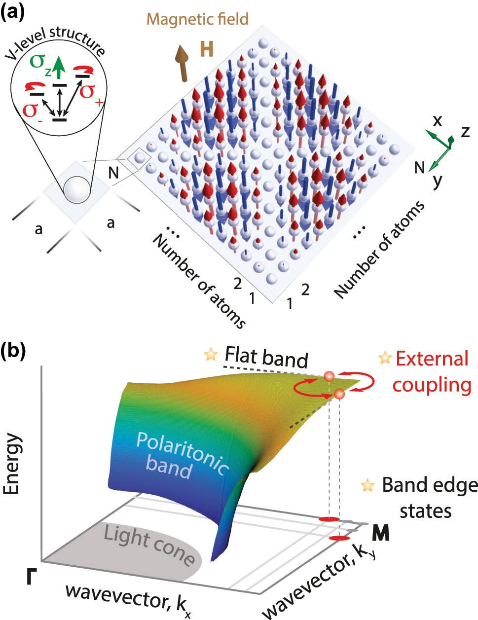
Schematic of the subradiant states formation in a regular planar atomic array. (a) A two-dimensional finite square regular lattice of N × N atoms with σ z transition, separated by distance a. The distribution of the highly non-radiative mode of B 2 symmetry is shown with arrows. (b) Polaritonic band diagram of the infinite dipolar lattice. The main mechanisms responsible for the formation of non-radiative states are shown with stars.
In this work, we consider planar finite arrays of two-level atoms arranged in different regular structures with the focus on the square atomic arrays schematically shown in Figure 1(a). We identify the main factors affecting the radiative losses suppression in such structures, including interference of the out-of-phase oscillating neighbor dipoles in the far zone, external coupling of the states associated with the symmetry of the structure, and “accidental” external coupling that emerges due to quasi-flat polaritonic band dispersion of the corresponding infinite lattice, see Figure 1(b). We establish the conditions under which these mechanisms are present and demonstrate the interplay between them on the example of the square array. We show that the radiative decay rate of the most subradiant states in square arrays decrease as fast as
2 General formalism
Let us consider an array of identical two-level atoms in free space with a transition frequency ω
0 (transition wavelength λ
0) and spontaneous decay rate
To describe such interaction, we introduce dipole moment operator of the ith atom as
where e d = d/d is the unit vector of the atomic transition dipole moment. In Eq. (1), the first term describes the coupling of atoms to free space, while the second one describes the atom–atom coupling. The above equation is obtained within the Markovian approximation by neglecting the frequency dependence of the Green’s tensor, G(R, ω) ≈ G(R, ω 0), which is justified by a very narrow resonance of a single atom Γ0 ≪ ω 0.
The eigenvalues and eigenstates of the Hamiltonian (1) define the complex eigenfrequencies ω j − iΓ j /2 and eigenfunctions Ψ(j) of the collective dipolar excitations, respectively. Real and imaginary parts of the eigenfrequency correspond to the frequency and radiative decay rate of the jth collective eigenstate. For convenience throughout the paper we define the frequency with respect to that of a single atom, Δω j = ω j − ω 0.
Normally, in the absence of the external magnetic field, atoms are spherically symmetric, and the simplest model of such an atom is the one with triply degenerate excited state (S ↔ P transition). In the presence of the z-oriented magnetic field (normal to the x − y plane of the array, see Figure 1(a)) the states of an atom can be spectrally separated into three states depending on the polarization of the transition dipole moment, σ −, σ +, or σ z . Consequently, the collective eigenstates of the planar arrays of such atoms can be considered separately for different polarizations of the atomic transitions.
3 Square atomic array
It is known that the radiative losses are mostly suppressed in symmetric structures, which possess fewer radiation channels than non-symmetric ones. In this section, we focus on one of the most simple and high-symmetry case of 2D atomic array N × N arranged is a square lattice with a period a. Such illustrative example allows us to demonstrate the competition between different mechanisms of the radiative loss suppression.
3.1 Classification of the collective eigenstates
The eigenstates of the finite lattices can be classified and characterized based on their distribution in the quasi-reciprocal space [19], [47], [48] which can be done by expanding the dipole moments distribution of the jth eigenstate Ψ(j) in the standing (Bloch) waves basis:
where
Alternative natural classification of the eigenstates is based on their symmetry properties. The square array belongs to the C
4v
point symmetry group and thus the eigenstates Ψ(j) should transform according to one of the irreducible representations (irreps) A
1, A
2, B
1, B
2, E. However, the basis given by Eq. (2) does not account for the specific symmetry of the square array. Therefore, not all of the basis states
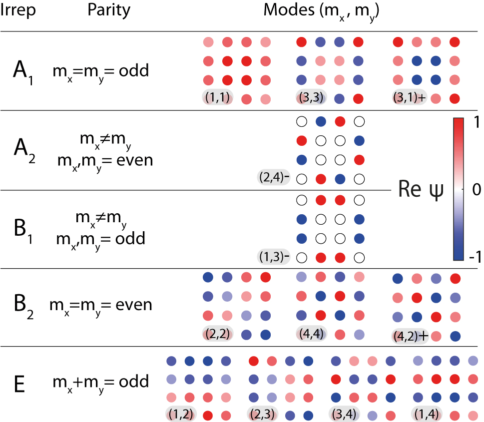
Symmetry classification of the basis functions
Antisymmetric modes transform according to A 2 or B 1, while symmetric modes transform according to A 1 or B 2 irrep.
3.2 Mechanism of the radiation suppression
If the eigenstate Ψ(j) of the atomic array is mainly characterized by a single dominant contribution of a basis state
The second factor affecting the radiative losses is associated with the symmetry of a given eigenstate, which is determined by the symmetry of the finite array. For instance, Bloch waves propagating in an infinite square lattice in directions near the M-point and symmetric with respect to the ΓM-direction are degenerate owing to the symmetry of the lattice, see Figure 1. However, in a finite array the degeneracy is lifted due to the external coupling of these waves according to Friedrich–Wintgen mechanism [49] leading to the formation of symmetric and antisymmetric states. The latter ones transform according to A 2 or B 1 irreps and are antisymmetric with respect to the diagonal vertical planes of symmetry n x = ±n y , i.e. the excitation of the corner dipole moments of such states is necessarily zero. Due to the suppressed scattering from the sharp edges of the structure, the radiative losses of these states can substantially decrease [48], [50], [51]. On the other hand, symmetric modes that transform according to A 1 or B 2 with non-zero corner dipole moments are characterized with the increased losses.
Additional mechanism of the losses suppression may appear due to the external coupling of the eigenstates that is not related to the symmetry of the infinite lattice or the finite array, but rather to the accidental degeneracy of the Bloch waves in the corresponding infinite lattice. As we show further, such regime can be realised for small enough periods, when the lattice dispersion becomes quasi-flat. In this case, two (or typically several) basis states interact via radiation continuum resulting in an additional suppression or increase of their radiative losses. The overall radiative losses of an eigenstate are then determined as a result of the competition between these three mechanisms of loss suppression. In order to determine which of the eigenstates exhibits minimal losses for a given size and period of the structure, we perform straight-forward numerical calculations and the results are presented in the next subsection.
3.3 Numerical calculations of the finite array eigenstates
In Figure 3(a) we show numerically calculated emission rates, normalized by the emission rate of a single atom, Γ/Γ0 for two collective states of the 12 × 12 square array as a function of the normalized period
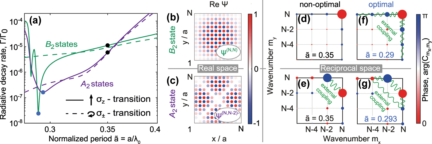
Characteristics of the subradiant states in 2D square array. (a) Normalized radiative decay rate of two most subradiant eigenstates corresponding to B
2 (green curves) and A
2 (violet curves) symmetry in 12 × 12 square array as a function of the normalized period
However, the radiative losses of such state are minimal only for the periods
Such antisymmetric subradiant states can also be viewed as the result of the external coupling between two eigenstates of the rectangular array that appears under stretching/squeezing the lattice to the square one [52], see also Supplementary Materials, Section A for the details. Consequently, the mechanism of the symmetry-induced external coupling is very sensitive to the deformation of the lattice: in a rectangular lattice the efficiency of the coupling drops very fast, resulting in the substantially increased losses of the
For even smaller lattice periods, the decay rate as a function of the period exhibits a minimum around
3.4 Infinite atomic lattices
Appearance of the external coupling near
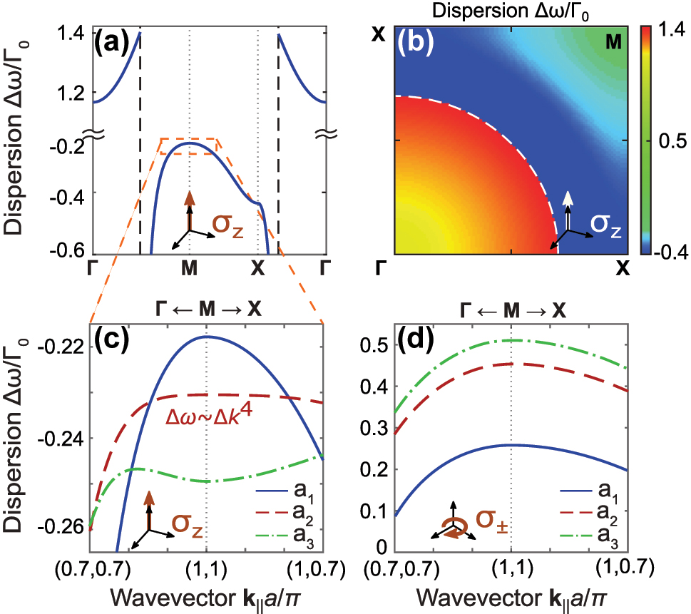
Dispersion of 2D square atomic lattice. (a, b) Dispersion of an infinite square lattice of σ
z
polarized atoms for the period
As it was shown in the previous subsection, the eigenstates of the finite arrays that are closest to the M-point, are the most subradiant due to the largest mismatch with the wavevectors of the free space. One can observe in Figure 4(c) that the dispersion near the M-point turns out to be qualitatively different for different periods. For the large periods
4 Discussion
4.1 Variation of the radiative losses with the size of arrays with different geometries
The mechanisms determining the formation of the subradiant states in atomic arrays that were shown on the example of the square geometry have rather general nature and are present in various configuration of atomic ensembles. Calculations performed for a few other main geometries of the regular atomic arrays such as rotated square, triangle, hexagon (see Supplementary Materials, Section C for the details) have revealed that the square geometry is preferable for the state lifetime. In Figure 5(b) we show decay rates of the four characteristic eigenstates, corresponding to different array geometries shown in Figure 5(a), as a function of the total number of the atoms N
tot, calculated for the non-optimal period

Scaling of the radiative losses with the size of the array. (a) Array geometries and wavefunctions of the most subradiant eigenstates. (b, c) Radiative losses of subradiant states as a function of the total number of atoms in the array N
s for different geometries for (b) fixed distance between the neighbor atoms
Another type of the eigenstate of the square array, A
1/B
2 states with the dominant ψ
(N,N) contribution, exhibit only
In Figure 5(c), we plot the calculated decay rates for the optimal periods
Note that the presented analysis on the asymptotic behavior of radiative losses was performed in the ideal case of a perfect periodicity of the array and the absence of various decoherence effects inevitably presented in any realistic system of coupled quantum emitters. For instance, disorder effects can significantly influence the radiative losses [54], especially in the case of subradiant states in large systems. While the signatures of subradiant states themselves can be detected in realistic systems, the observation of effects related to the quasi-flat dispersion [20] and the symmetry of states is currently quite challenging. At the same time, it was recently shown for atomic clouds, that subradiance is quite robust to thermal decoherence [55].
4.2 Excitation of the subradiant states
In order to demonstrate the possibility of excitation of the strongly subradiant states appearing for the σ z polarization, we consider the scattering of vector Bessel beams [56], [57] by a square atomic array. The use of such specific excitation field has two underlying reasons. First, we consider the states characterized by large wavevectors. The use of Bessel beams, which can have arbitrary angular momentum, allows for partially matching the azimuthal component of the wavevector of the incident field to that of the eigenstate. Second, Bessel beams have non-zero longitudinal electric field, which allows for efficient excitation of the σ z polarized states. The considered highly inhomogeneous incident field may excite various modes of the lattice with different efficiency, therefore we have optimized orbital number of the beam m to maximize the overlap between external electric field and the desired collective state, see the Supplementary Materials, Section E for details of the scattering calculations. We need to stress here that while the full description of the quantum dynamics of the considered system, accounting for various atomic decoherence mechanisms, requires approach based a master equation for the density matrix [46], [58], here we use semiclassical simulations (see Supplementary Materials, Section E), which give exactly the same results for spontaneous emission decoherence.
In Figure 6, we show numerically calculated scattering cross-section spectra of 6 × 6 square atomic array irradiated by normally incident vector Bessel beam with a spin s = 1 due to circular polarization, and orbital numbers l = 7 or l = 9 [57]. Total cross-section consists of various peaks matching eigenmodes of the lattice characterized with different dominant basis states. The parameters of the beams were chosen to achieve the maximum coupling with the eigenstates with dominant contribution of basis states
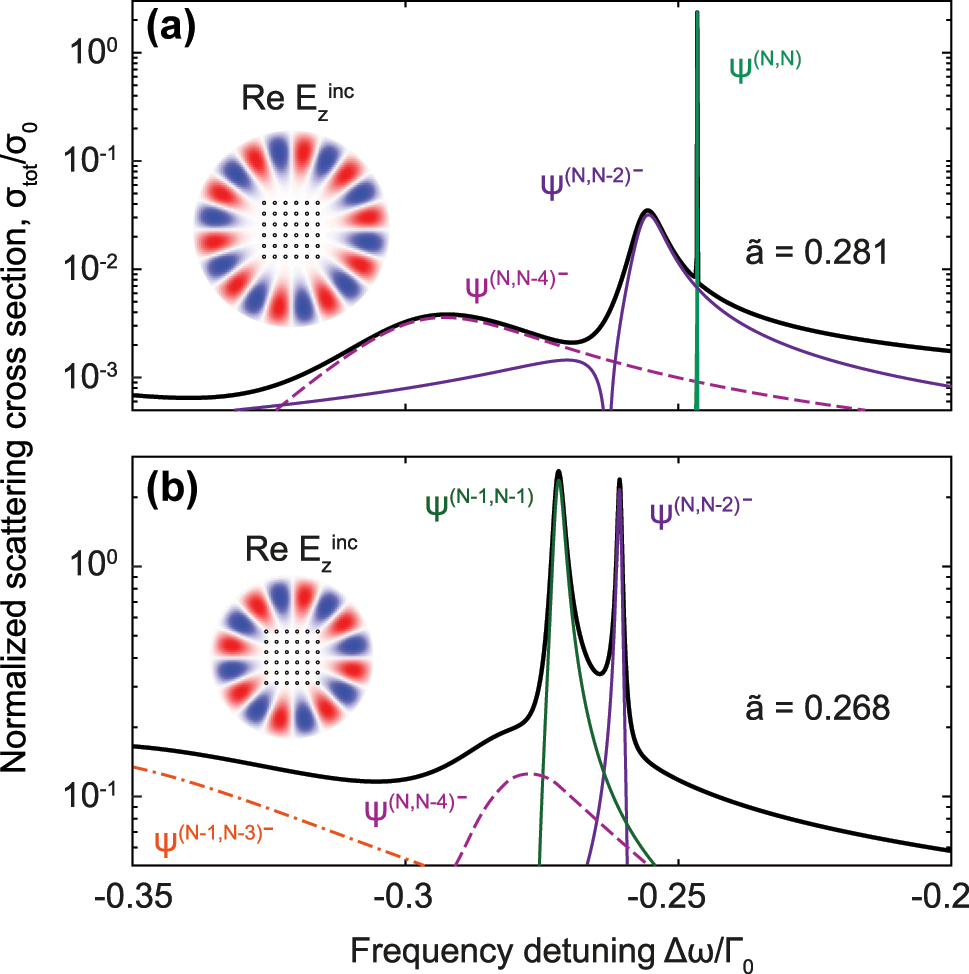
Normalized scattering cross section spectra of 6 × 6 square atomic lattice irradiated by Bessel beam with (a) azimuthal number m = 9 and period
As one can see in the insets of Figure 6, the optimal incident field profile barely overlaps the atomic array from the outside, setting π phase shift between neighboring atoms at the edges with almost no influence at internal atoms. Therefore, a total angular momentum of the beam l + s matches to either a half of total number of edge atoms 2(N − 1), see Figure 6(a), or the same number but excluding corner atoms 2(N − 2), see Figure 6(b). In the first case, the beam is capable to excite the B
2 state with a dominant ψ
(N,N) contribution. In the second case, where the field at the corners is absent, it is optimal to excite A
2 state with a dominant
4.3 Relation to high quality modes in nanophotonic cavities
Importantly, the generality of the reported results is also underlined by the tight connection to the research area of engineering of planar dielectric nanophotonic cavities, such as homogeneous dielectric cavities [52], [ and periodic or quasi-periodic nanostructured cavities [65], [66].
The resonators made of homogeneous dielectric are expected to have the highest Q-factors for spherical or cylindrical geometries, which exhibit the highest symmetry. However, the utilized fabrication methods or proposed technological applications sometimes demand the use of the cavities of the other shapes, e.g. cubes, squares, hexagons etc., which were also shown to support rather high Q-factors and have potential in development of micro and nanolasers [52], [67], [68]. The dispersion of homogeneous dielectric is, however, quasi-linear and the external coupling due to quasi-flat band in this case is not possible. Unlike the homogeneous cavitites, the dispersion in the nanostructured ones, i.e. photonic-crystal or nanoparticle cavities, is more tunable. Consequently, quasi-flat and nonmonotonous bands in such structures result in the quality factor boost in the finite arrays [66]. By proper translating all mechanisms of the subradiant states formation reported in this work for the dipolar arrays onto the nanophotonic platform could lead to the development of the novel designs of the compact optical micro and nanocavities.
5 Summary
To summarize, we have studied main factors that define the radiative loss suppression in finite-size planar atomic arrays. We have shown that the square arrays support eigenstates with minimal losses among different regular arrangements of the atoms, that scale with the number of atoms as
Funding source: Russian Science Foundation
Award Identifier / Grant number: 22-72-10047
Acknowledgments
We thank Yuri Kivshar and Ivan Iorsh for significant discussions.
-
Research funding: The work was supported by the Federal Academic Leadership Program Priority 2030. The numerical computations of radiative lifetime in finite structures were supported by the Russian Science Foundations grant No. 22-72-10047. M. P. acknowledges support from the Foundation for the Advancement of Theoretical Physics and Mathematics “BASIS”.
-
Author contributions: I.V. and N.U. performed numerical calculations of the eigenstates' characteristics. R.S. performed symmetry analysis of the eigenstates. I.V. calculated the dispersion of the polaritonic modes in infinite arrays and simulated extinction cross sections of light scattered on the dipolar array. I.V., R.S. and M.P. prepared graphical data. D.K. provided unprecidental guidance to I.V. and N.U. in all technical details of the used theoretical methods. R.S, A.S., and M.P. wrote the manuscript and supported I.V. and N.U. in mastering physics of cooperative quantum excitations. All authors participated in the discussion of the obtained results and have accepted responsibility for the entire content of this manuscript and approved its submission.
-
Conflict of interest: Authors state no conflicts of interest.
-
Informed consent: Informed consent was obtained from all individuals included in this study.
-
Ethical approval: The conducted research is not related to either human or animals use.
-
Data availability: Data sharing is not applicable to this article as no datasets were generated or analysed during the current study.
References
[1] D. Barredo, S. de Léséleuc, V. Lienhard, T. Lahaye, and A. Browaeys, “An atom-by-atom assembler of defect-free arbitrary two-dimensional atomic arrays,” Science, vol. 354, no. 6315, pp. 1021–1023, 2016. https://doi.org/10.1126/science.aah3778.Suche in Google Scholar PubMed
[2] D. Barredo, V. Lienhard, S. De Léséleuc, T. Lahaye, and A. Browaeys, “Synthetic three-dimensional atomic structures assembled atom by atom,” Nature, vol. 561, no. 7721, pp. 79–82, 2018. https://doi.org/10.1038/s41586-018-0450-2.Suche in Google Scholar PubMed
[3] C. Gross and I. Bloch, “Quantum simulations with ultracold atoms in optical lattices,” Science, vol. 357, no. 6355, pp. 995–1001, 2017. https://doi.org/10.1126/science.aal3837.Suche in Google Scholar PubMed
[4] J. Rui, et al.., “A subradiant optical mirror formed by a single structured atomic layer,” Nature, vol. 583, no. 7816, pp. 369–374, 2020. https://doi.org/10.1038/s41586-020-2463-x.Suche in Google Scholar PubMed
[5] N. V. Corzo, et al.., “Large bragg reflection from one-dimensional chains of trapped atoms near a nanoscale waveguide,” Phys. Rev. Lett., vol. 117, no. 13, p. 133603, 2016. https://doi.org/10.1103/physrevlett.117.133603.Suche in Google Scholar
[6] A. S. Prasad, et al.., “Correlating photons using the collective nonlinear response of atoms weakly coupled to an optical mode,” Nat. Photonics, vol. 14, no. 12, pp. 719–722, 2019. https://doi.org/10.1038/s41566-020-0692-z.Suche in Google Scholar
[7] C. Liedl, S. Pucher, F. Tebbenjohanns, P. Schneeweiss, and A. Rauschenbeutel, “Collective radiation of a cascaded quantum system: from timed Dicke states to inverted ensembles,” Phys. Rev. Lett., vol. 130, no. 16, p. 163602, 2023. https://doi.org/10.1103/physrevlett.130.163602.Suche in Google Scholar PubMed
[8] N. V. Corzo, J. Raskop, A. Chandra, A. S. Sheremet, B. Gouraud, and J. Laurat, “Waveguide-coupled single collective excitation of atomic arrays,” Nature, vol. 566, no. 7744, pp. 359–362, 2019. https://doi.org/10.1038/s41586-019-0902-3.Suche in Google Scholar PubMed
[9] M. Gross and S. Haroche, “Superradiance: an essay on the theory of collective spontaneous emission,” Phys. Rep., vol. 93, no. 5, pp. 301–396, 1982. https://doi.org/10.1016/0370-1573(82)90102-8.Suche in Google Scholar
[10] V. E. Andreev and Y. Il’inskii, Cooperative Effects in Optics, Superradiance and Phase Transitions, Malvern Physics Series, Boca Raton, Florida, CRC Press, 1993.Suche in Google Scholar
[11] S. J. Masson and A. Asenjo-Garcia, “Universality of Dicke superradiance in arrays of quantum emitters,” Nat. Commun., vol. 13, no. 2285, pp. 1–7, 2022. https://doi.org/10.1038/s41467-022-29805-4.Suche in Google Scholar PubMed PubMed Central
[12] S. Jahani and Z. Jacob, “All-dielectric metamaterials,” Nat. Nanotechnol., vol. 11, no. 1, pp. 23–36, 2016. https://doi.org/10.1038/nnano.2015.304.Suche in Google Scholar PubMed
[13] A. I. Kuznetsov, A. E. Miroshnichenko, M. L. Brongersma, Y. S. Kivshar, and B. Luk’yanchuk, “Optically resonant dielectric nanostructures,” Science, vol. 354, no. 6314, p. aag2472, 2016. https://doi.org/10.1126/science.aag2472.Suche in Google Scholar PubMed
[14] K. Grotov, et al.., “Genetically designed wire bundle superscatterers,” IEEE Trans. Antenn. Propag., vol. 70, no. 10, pp. 9621–9629, 2022. https://doi.org/10.1109/tap.2022.3177531.Suche in Google Scholar
[15] A. Mikhailovskaya, et al.., “Superradiant scattering limit for arrays of subwavelength scatterers,” Phys. Rev. Appl., vol. 18, no. 5, p. 054063, 2022. https://doi.org/10.1103/physrevapplied.18.054063.Suche in Google Scholar
[16] R. H. Dicke, “Coherence in spontaneous radiation processes,” Phys. Rev., vol. 93, no. 1, pp. 99–110, 1954. https://doi.org/10.1103/physrev.93.99.Suche in Google Scholar
[17] D. Pavolini, A. Crubellier, P. Pillet, L. Cabaret, and S. Liberman, “Experimental evidence for subradiance,” Phys. Rev. Lett., vol. 54, no. 17, pp. 1917–1920, 1985. https://doi.org/10.1103/physrevlett.54.1917.Suche in Google Scholar
[18] R. G. DeVoe and R. G. Brewer, “Observation of superradiant and subradiant spontaneous emission of two trapped ions,” Phys. Rev. Lett., vol. 76, no. 12, pp. 2049–2052, 1996. https://doi.org/10.1103/physrevlett.76.2049.Suche in Google Scholar
[19] A. S. Sheremet, M. I. Petrov, I. V. Iorsh, A. V. Poshakinskiy, and A. N. Poddubny, “Waveguide quantum electrodynamics: collective radiance and photon-photon correlations,” Rev. Mod. Phys., vol. 95, no. 1, p. 015002, 2023. https://doi.org/10.1103/revmodphys.95.015002.Suche in Google Scholar
[20] D. F. Kornovan, N. V. Corzo, J. Laurat, and A. S. Sheremet, “Extremely subradiant states in a periodic one-dimensional atomic array,” Phys. Rev. A, vol. 100, no. 6, p. 063832, 2019. https://doi.org/10.1103/physreva.100.063832.Suche in Google Scholar
[21] R. Pennetta, D. Lechner, M. Blaha, A. Rauschenbeutel, P. Schneeweiss, and J. Volz, “Observation of coherent coupling between super- and subradiant states of an ensemble of cold atoms collectively coupled to a single propagating optical mode,” Phys. Rev. Lett., vol. 128, no. 20, p. 203601, 2022. https://doi.org/10.1103/physrevlett.128.203601.Suche in Google Scholar
[22] W. Guerin, M. O. Araújo, and R. Kaiser, “Subradiance in a large cloud of cold atoms,” Phys. Rev. Lett., vol. 116, no. 8, p. 083601, 2016. https://doi.org/10.1103/physrevlett.116.083601.Suche in Google Scholar
[23] G. Facchinetti and J. Ruostekoski, “Interaction of light with planar lattices of atoms: reflection, transmission, and cooperative magnetometry,” Phys. Rev. A, vol. 97, no. 2, p. 023833, 2018. https://doi.org/10.1103/physreva.97.023833.Suche in Google Scholar
[24] M. Saffman, T. G. Walker, and K. Mølmer, “Quantum information with Rydberg atoms,” Rev. Mod. Phys., vol. 82, no. 3, pp. 2313–2363, 2010. https://doi.org/10.1103/revmodphys.82.2313.Suche in Google Scholar
[25] K. Srakaew, et al.., “A subwavelength atomic array switched by a single Rydberg atom,” Nat. Phys., vol. 19, no. 5, pp. 714–719, 2023. https://doi.org/10.1038/s41567-023-01959-y.Suche in Google Scholar
[26] K. E. Ballantine and J. Ruostekoski, “Parity-time symmetry and coherent perfect absorption in a cooperative atom response,” Nanophotonics, vol. 10, no. 4, pp. 1357–1366, 2021. https://doi.org/10.1515/nanoph-2020-0635.Suche in Google Scholar
[27] K. E. Ballantine and J. Ruostekoski, “Cooperative optical wavefront engineering with atomic arrays,” Nanophotonics, vol. 10, no. 7, pp. 1901–1909, 2021. https://doi.org/10.1515/nanoph-2021-0059.Suche in Google Scholar
[28] N. Nefedkin, M. Cotrufo, and A. Alú, “Nonreciprocal total cross section of quantum metasurfaces,” Nanophotonics, vol. 12, no. 3, pp. 589–606, 2023. https://doi.org/10.1515/nanoph-2022-0596.Suche in Google Scholar
[29] S. P. Pedersen, L. Zhang, and T. Pohl, “Quantum nonlinear metasurfaces from dual arrays of ultracold atoms,” Phys. Rev. Res., vol. 5, no. 23, p. L012047, 2023. https://doi.org/10.1103/physrevresearch.5.l012047.Suche in Google Scholar
[30] G. Facchinetti, S. D. Jenkins, and J. Ruostekoski, “Storing light with subradiant correlations in arrays of atoms,” Phys. Rev. Lett., vol. 117, no. 24, p. 243601, 2016. https://doi.org/10.1103/physrevlett.117.243601.Suche in Google Scholar PubMed
[31] K. E. Ballantine and J. Ruostekoski, “Subradiance-protected excitation spreading in the generation of collimated photon emission from an atomic array,” Phys. Rev. Res., vol. 2, no. 2, p. 023086, 2020. https://doi.org/10.1103/physrevresearch.2.023086.Suche in Google Scholar
[32] C. W. Hsu, B. Zhen, A. D. Stone, J. D. Joannopoulos, and M. Soljačić, “Bound states in the continuum,” Nat. Rev. Mater., vol. 1, no. 9, p. 16048, 2016. https://doi.org/10.1038/natrevmats.2016.48.Suche in Google Scholar
[33] K. Koshelev, Z. Sadrieva, A. Shcherbakov, Y. Kivshar, and A. Bogdanov, “Bound states in the continuum in photonic structures,” Phys. Usp., vol. 66, no. 5, pp. 494–517, 2021. https://doi.org/10.3367/ufne.2021.12.039120.Suche in Google Scholar
[34] S. Gladyshev, A. Shalev, K. Frizyuk, K. Ladutenko, and A. Bogdanov, “Bound states in the continuum in multipolar lattices,” Phys. Rev. B, vol. 105, no. 24, p. L241301, 2022. https://doi.org/10.1103/physrevb.105.l241301.Suche in Google Scholar
[35] Z. Sadrieva, K. Frizyuk, M. Petrov, Y. Kivshar, and A. Bogdanov, “Multipolar origin of bound states in the continuum,” Phys. Rev. B, vol. 100, no. 11, p. 115303, 2019. https://doi.org/10.1103/physrevb.100.115303.Suche in Google Scholar
[36] O. Rubies-Bigorda, V. Walther, T. L. Patti, and S. F. Yelin, “Photon control and coherent interactions via lattice dark states in atomic arrays,” Phys. Rev. Res., vol. 4, no. 1, p. 013110, 2022. https://doi.org/10.1103/physrevresearch.4.013110.Suche in Google Scholar
[37] M. B. De Paz and P. A. Huidobro, “Bound states in the continuum in subwavelength emitter arrays,” Phys. Rev. Res., vol. 5, no. 3, p. 033108, 2023. https://doi.org/10.1103/physrevresearch.5.033108.Suche in Google Scholar
[38] D. F. Kornovan, R. S. Savelev, Y. Kivshar, and M. I. Petrov, “High-Q localized states in finite arrays of subwavelength resonators,” ACS Photonics, vol. 8, no. 12, pp. 3627–3632, 2021. https://doi.org/10.1021/acsphotonics.1c01262.Suche in Google Scholar
[39] Y. X. Zhang and K. Mølmer, “Subradiant emission from regular atomic arrays: universal scaling of decay rates from the generalized Bloch theorem,” Phys. Rev. Lett., vol. 125, no. 25, p. 253601, 2020. https://doi.org/10.1103/physrevlett.125.253601.Suche in Google Scholar PubMed
[40] A. Asenjo-Garcia, J. D. Hood, D. E. Chang, and H. J. Kimble, “Atom-light interactions in quasi-one-dimensional nanostructures: a green’s-function perspective,” Phys. Rev. A, vol. 95, no. 3, p. 033818, 2017. https://doi.org/10.1103/physreva.95.033818.Suche in Google Scholar
[41] S. Y. Buhmann, Dispersion Forces I: Macroscopic Quantum Electrodynamics and Ground-State Casimir, Casimir–Polder and van der Waals Forces (Springer Tracts in Modern Physics, 247), Berlin, Germany, Springer, 2015.Suche in Google Scholar
[42] L. Novotny and B. Hecht, Principles of Nano-Optics, Cambridge, England, UK, Cambridge University Press, 2012.10.1017/CBO9780511794193Suche in Google Scholar
[43] P. A. Belov and C. R. Simovski, “Homogenization of electromagnetic crystals formed by uniaxial resonant scatterers,” Phys. Rev. E, vol. 72, no. 2, p. 026615, 2005. https://doi.org/10.1103/physreve.72.026615.Suche in Google Scholar PubMed
[44] V. A. Markel and A. K. Sarychev, “Propagation of surface plasmons in ordered and disordered chains of metal nanospheres,” Phys. Rev. B, vol. 75, no. 8, p. 085426, 2007. https://doi.org/10.1103/physrevb.75.085426.Suche in Google Scholar
[45] M. Reitz, C. Sommer, and C. Genes, “Cooperative quantum phenomena in light-matter platforms,” PRX Quantum, vol. 3, no. 1, p. 010201, 2021. https://doi.org/10.1103/prxquantum.3.010201.Suche in Google Scholar
[46] J. Ruostekoski, “Cooperative quantum-optical planar arrays of atoms,” Phys. Rev. A, vol. 108, no. 3, p. 030101, 2023, https://doi.org/10.1103/physreva.108.030101.Suche in Google Scholar
[47] D. F. Kornovan, A. S. Sheremet, and M. I. Petrov, “Collective polaritonic modes in an array of two-level quantum emitters coupled to an optical nanofiber,” Phys. Rev. B, vol. 94, no. 24, p. 245416, 2016. https://doi.org/10.1103/physrevb.94.245416.Suche in Google Scholar
[48] A. Asenjo-Garcia, M. Moreno-Cardoner, A. Albrecht, H. J. Kimble, and D. E. Chang, “Exponential improvement in photon storage fidelities using subradiance and “selective radiance” in atomic arrays,” Phys. Rev. X, vol. 7, no. 3, p. 031024, 2017. https://doi.org/10.1103/physrevx.7.031024.Suche in Google Scholar
[49] H. Friedrich and D. Wintgen, “Interfering resonances and bound states in the continuum,” Phys. Rev. A, vol. 32, no. 6, pp. 3231–3242, 1985. https://doi.org/10.1103/physreva.32.3231.Suche in Google Scholar PubMed
[50] A. N. Poddubny, “Quasiflat band enabling subradiant two-photon bound states,” Phys. Rev. A, vol. 101, no. 4, pp. 1–8, 2020. https://doi.org/10.1103/physreva.101.043845.Suche in Google Scholar
[51] J. Wiersig, “Formation of long-lived, scarlike modes near avoided resonance crossings in optical microcavities,” Phys. Rev. Lett., vol. 97, no. 25, p. 253901, 2006. https://doi.org/10.1103/physrevlett.97.253901.Suche in Google Scholar
[52] Y.-D. Yang and Y.-Z. Huang, “Mode characteristics and directional emission for square microcavity lasers,” J. Phys. D Appl. Phys., vol. 49, no. 25, p. 253001, 2016. https://doi.org/10.1088/0022-3727/49/25/253001.Suche in Google Scholar
[53] A. N. Poddubny, P. A. Belov, P. Ginzburg, A. V. Zayats, and Y. S. Kivshar, “Microscopic model of Purcell enhancement in hyperbolic metamaterials,” Phys. Rev. B, vol. 86, no. 3, p. 035148, 2012. https://doi.org/10.1103/physrevb.86.035148.Suche in Google Scholar
[54] N. O. Gjonbalaj, S. Ostermann, and S. F. Yelin, “Modifying cooperative decay via disorder in atom arrays,” arXiv preprint arXiv:2309.04384, 2023.10.1103/PhysRevA.109.013720Suche in Google Scholar
[55] P. Weiss, A. Cipris, M. O. Araújo, R. Kaiser, and W. Guerin, “Robustness of Dicke subradiance against thermal decoherence,” Phys. Rev. A, vol. 100, no. 3, p. 033833, 2019. https://doi.org/10.1103/physreva.100.033833.Suche in Google Scholar
[56] B. Richards and E. Wolf, “Electromagnetic diffraction in optical systems, II. Structure of the image field in an aplanatic system,” Proc. R. Soc. London A - Math. Phys. Sci., vol. 253, no. 1274, pp. 358–379, 1959.10.1098/rspa.1959.0200Suche in Google Scholar
[57] V. Kotlyar, A. G. Nalimov, and S. S. Stafeev, “Exploiting the circular polarization of light to obtain a spiral energy flow at the subwavelength focus,” J. Opt. Soc. Am. B, vol. 36, no. 10, pp. 2850–2855, 2019. https://doi.org/10.1364/josab.36.002850.Suche in Google Scholar
[58] R. H. Lehmberg, “Radiation from an N-atom system. I. General formalism,” Phys. Rev. A, vol. 2, no. 3, pp. 883–888, 1970. https://doi.org/10.1103/physreva.2.883.Suche in Google Scholar
[59] W.-H. Guo, Y.-Z. Huang, Q.-Y. Lu, and L.-J. Yu, “Modes in square resonators,” IEEE J. Quantum Electron., vol. 39, no. 12, pp. 1563–1566, 2003. https://doi.org/10.1109/jqe.2003.819562.Suche in Google Scholar
[60] C. Li, L. Zhou, S. Zheng, and A. W. Poon, “Silicon polygonal microdisk resonators,” IEEE J. Sel. Top. Quantum Electron., vol. 12, no. 6, pp. 1438–1449, 2006. https://doi.org/10.1109/jstqe.2006.883150.Suche in Google Scholar
[61] Y.-D. Yang and Y.-Z. Huang, “Mode analysis and q-factor enhancement due to mode coupling in rectangular resonators,” IEEE J. Quantum Electron., vol. 43, no. 6, pp. 497–502, 2007. https://doi.org/10.1109/jqe.2007.897879.Suche in Google Scholar
[62] Y.-D. Yang and Y.-Z. Huang, “Symmetry analysis and numerical simulation of mode characteristics for equilateral-polygonal optical microresonators,” Phys. Rev. A, vol. 76, no. 2, p. 023822, 2007. https://doi.org/10.1103/physreva.76.023822.Suche in Google Scholar
[63] S. Bittner, E. Bogomolny, B. Dietz, M. Miski-Oglu, and A. Richter, “Experimental observation of localized modes in a dielectric square resonator,” Phys. Rev. E, vol. 88, no. 6, p. 062906, 2013. https://doi.org/10.1103/physreve.88.062906.Suche in Google Scholar
[64] H. Cao and J. Wiersig, “Dielectric microcavities: model systems for wave chaos and non-hermitian physics,” Rev. Mod. Phys., vol. 87, no. 1, pp. 61–111, 2015. https://doi.org/10.1103/revmodphys.87.61.Suche in Google Scholar
[65] K. K. Tsia and A. W. Poon, “Dispersion-guided resonances in two-dimensional photonic-crystal-embedded microcavities,” Opt. Express, vol. 12, no. 23, pp. 5711–5722, 2004. https://doi.org/10.1364/opex.12.005711.Suche in Google Scholar PubMed
[66] H. Noh, J.-K. Yang, I. Vitebskiy, A. Figotin, and H. Cao, “Giant resonances near the split band edges of two-dimensional photonic crystals,” Phys. Rev. A, vol. 82, no. 1, p. 013801, 2010. https://doi.org/10.1103/physreva.82.013801.Suche in Google Scholar
[67] Z. Liu, et al.., “Robust subwavelength single-mode perovskite nanocuboid laser,” ACS Nano, vol. 12, no. 6, pp. 5923–5931, 2018. https://doi.org/10.1021/acsnano.8b02143.Suche in Google Scholar PubMed
[68] E. Tiguntseva, et al.., “Room-temperature lasing from mie-resonant nonplasmonic nanoparticles,” ACS Nano, vol. 14, no. 7, pp. 8149–8156, 2020. https://doi.org/10.1021/acsnano.0c01468.Suche in Google Scholar PubMed
Supplementary Material
This article contains supplementary material (https://doi.org/10.1515/nanoph-2023-0624).
© 2024 the author(s), published by De Gruyter, Berlin/Boston
This work is licensed under the Creative Commons Attribution 4.0 International License.
Artikel in diesem Heft
- Frontmatter
- Research Articles
- Low sidelobe silicon optical phased array with Chebyshev amplitude distribution
- Identifying topology of leaky photonic lattices with machine learning
- Can photonic heterostructures provably outperform single-material geometries?
- Strongly subradiant states in planar atomic arrays
- Spatially inhomogeneous inverse Faraday effect provides tunable nonthermal excitation of exchange dominated spin waves
- Micro-nano hierarchical urchin-like ZnO/Ag hollow sphere for SERS detection and photodegradation of antibiotics
- Optical mode-controlled topological edge state in waveguide lattice
- Electrically-switched differential microscopy based on computing liquid-crystal platforms
- Fabrication of 1 × N integrated power splitters with arbitrary power ratio for single and multimode photonics
- Giant enhancement of optical nonlinearity from monolayer MoS2 using plasmonic nanocavity
- Manipulating chiral photon generation from plasmonic nanocavity-emitter hybrid systems: from weak to strong coupling
- Over a thousand-fold enhancement of the spontaneous emission rate for stable core−shell perovskite quantum dots through coupling with novel plasmonic nanogaps
- Coherent perfect loss with single and broadband resonators at photonic crystal nanobeam