
Color display and encryption with a plasmonic polarizing metamirror
-
Maowen Song


Abstract
Structural colors emerge when a particular wavelength range is filtered out from a broadband light source. It is regarded as a valuable platform for color display and digital imaging due to the benefits of environmental friendliness, higher visibility, and durability. However, current devices capable of generating colors are all based on direct transmission or reflection. Material loss, thick configuration, and the lack of tunability hinder their transition to practical applications. In this paper, a novel mechanism that generates high-purity colors by photon spin restoration on ultrashallow plasmonic grating is proposed. We fabricated the sample by interference lithography and experimentally observed full color display, tunable color logo imaging, and chromatic sensing. The unique combination of high efficiency, high-purity colors, tunable chromatic display, ultrathin structure, and friendliness for fabrication makes this design an easy way to bridge the gap between theoretical investigations and daily-life applications.
1 Introduction
The collective oscillation of free electrons and photons at the interfaces of metal and dielectric materials are called surface plasmons [1], [2], which have attracted tremendous attention and provided a platform to investigate a great deal of novel physical properties such as perfect absorption [3], [4], [5], [6], subdiffraction focusing [7], [8], [9], [10], and negative refraction [11], [12], [13]. Among the plentiful research subjects in the big family of plasmonic metamaterials, one of the intensively investigated topics in recent decades is the design of color filters [14], [15], [16], [17], [18], [19], [20], [21], [22], [23], [24], [25], where a specific color is observed if the scattered light of a particular wavelength range comes into our eyes when an object is illuminated with white light. By exploiting the plasmonic subwavelength structures, such as nanohole or nanoparticle arrays [1], [14], light transmission/reflection can be selectively enhanced or hindered at a resonant wavelength. These phenomena indicate that the plasmonic resonant wavelength is highly dependent on the geometric sizes, so that different designs perform well at any desired optical wavelength bands. However, the peak location lacks dynamic tunability and the resonant bandwidth is still relatively broad as metallic loss plays an important role in the visible regime, let alone the thick architectures pose a great challenge in the fabricating process. Recently, highly efficient compact color filters constructed from a single layer of resonators are employed to produce colors by hybrid plasmon resonance [20] or Fano resonance [21]. Unfortunately, the purity of colors and the tunable range in the CIE 1931 chromaticity diagram are not wide enough.
The recent designs of color filters are all based on the direct transmission or reflection of light wave. These configurations are presented as periodically arranged nanopatches or nanorods atop the substrate. When the distance between adjacent elements is close enough, the coupling between neighboring metallic elements results in a significantly enhanced electric field. Therefore, the dense arrangement of elements seems to be a necessary requirement to design color filters by introducing a strong near-field coupling. Electron-beam lithography (EBL) and focused ion-beam milling (FIB) offer the platform to fabricate such nanostructures with small separations; however, these methods are expensive and inefficient. Interference lithography, which provides a cost-effective approach to manufacture large-area mass-production periodic nanostructures, is adopted in our work and expected to achieve ultrasmooth silver grating combined with strip-off technology [26].
In this paper, we proposed a new mechanism to achieve high-purity red, green, and blue (RGB) structural colors. Different from any current designs, our metamirror based on plasmonic shallow grating (PSG) produces colors by photon spin restoration, which reflects a circularly polarized (CP) light to its copolarized state at specific wavelengths (it is well known that the spin direction would be reversed when a CP light is reflected from a common mirror) [27]. The full-width at half-maximum (FWHM) of ~16 nm with high efficiency (~75%) has been theoretically obtained and experimentally demonstrated. This PSG architecture uniquely combines a number of advantages: high-purity colors, high efficiency, ultrathin and large area configuration, friendly for nanofabrication, and in particular the color display can be controlled by tuning the polarization state of incident white light or reflective light. All these fascinating merits offer a wide range of valuable applications, including active color pixels, chromatic data encryption, and biomedical sensing.
2 Results
The concept of spin restoration induced by light-PSG interaction is schematically illustrated in Figure 1A. The detailed derivation about how to preserve spin state in metamirrors has been analyzed in previous works [28], [29], [30], [31]. It should be remembered that a 180° phase difference between the two linearly polarized (LP) components along the x and y directions (Φx and Φy) is necessary at normal incidence. In the optical experiment set-up, a relatively narrow bandwidth of commercial quarter-wave plate poses challenges to generate broadband CP light and measure the copolarized counterpart. To have a clear vision of the spin restoration, a LP incident light polarized at 45° with respect to the grating is used instead, as the PSG will convert it to its cross-polarization when |Φx−Φy|=180° is achieved.
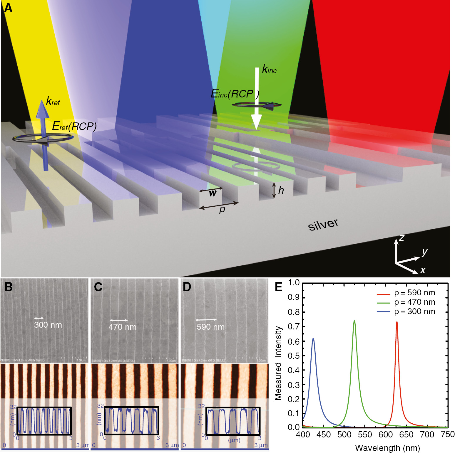
High-performance structural color filters formed by plasmonic metamirror. (A) Schematic diagram of the light-structure interaction. White and blue arrows indicate the incident and reflective right-handed CP light. Black arrows depict the spin state of the incident and reflective waves. Red, yellow, green, and blue beams represent the reflected waves with restored spin states. The duty cycle (w/p) is fixed to be 0.55. (B–D) SEM and AFM images of the prepared filters with periods of 300, 470, and 590 nm. The samples exhibit uniform line width, high fidelity, and smooth surface morphology. (E) Experimentally measured reflection spectra of the cross-polarized scattered light for 45° polarized LP at normal incidence.
Silver was chosen here due to its excellent optical properties, with its interband transition lying outside the visible bands and enabling strong plasmonic responses. With the collective contributions of the propagating surface plasmon (PSP) resonance and localized surface plasmon (LSP) resonance, a sharp peak occurs at the reflective cross-polarization spectra, so that a specific color can be efficiently filtered out. To realize a broad palette of dazzling colors besides the three primary colors of RGB, it is necessary to change the periods of the PSGs to make the spectral peak locations undergo a continuous blue shift from 668 to 430 nm. The proposed PSG consists of a 1D periodic arrangement of silver grooves etched on a silver film as shown in Figure 1A. The dimensions are chosen as w=0.55p, h=30 nm, where p-w and h represent the width and depth of the groove, respectively. Here, p represents the period of the PSG, which is kept subwavelength in our designs to avoid unexpected high-order diffractions. The dielectric function of silver is obtained from the data measured by Johnson and Christy [32]. The commercial software CST MWS was adopted to calculate the building blocks, whereas unit cell boundary conditions were used along the x and y directions. Figure 1B–D displays the scanning electron microscopy (SEM) and atomic force microscopy (AFM) images of the samples fabricated by interference lithography. Three periods of 300, 470, and 590 nm are shown without the loss of any generality. As observed in the SEM images, all three prepared filters exhibit uniform line width and high fidelity. The measured morphology images of a small part of the PSG indicate that the texture is patterned with a 30 nm peak-to-valley profile and a surface roughness of about 0.5 nm [root mean square (RMS)] is achieved. Figure 1E depicts the experimentally measured reflective cross-polarization spectra. Three sharp peaks are observed at 627 nm (red), 525 nm (green), and 430 nm (blue), whereas the corresponding periods of PSGs are 590, 470, and 300 nm, respectively. The reflective efficiency peaks reach up to 75%, with the smallest FWHM to be only ~16 nm. Furthermore, the magnitudes at off-resonant wavelengths are strongly suppressed, both of which help to improve the purity of the generated colors. It is highly remarkable that such fascinating performance is obtained by the PSGs consisting of only 30-nm-thick functional layer mounted on the silver mirror (~100 nm), which enables the construction of ultrathin chromatic display devices.
The fabricating process of the PSG color filters is plotted in Figure S1 in the Supporting Information. The grating is first fabricated on silicon via laser interference lithography and transferred to silver film by template stripping (TS) [33]. It is of great importance to smooth the PSG, as the surface roughness will deteriorate the performance by inducing scattering loss, which broadens the resonant bandwidth, especially when the groove depth is only 30 nm. To experimentally measure the performance of the PSG color filters with a size of 30×30 mm, a commercial spectrophotometer (Lambda 1050, PerkinElmer, Inc.) is used. Figure S2 shows the optical experimental set-up.
For the proposed PSG color filters, a broad palette of RGB colors can be continuously produced by varying the periods of the gratings. Figure 2A shows the calculated and measured reflective cross-polarization spectra, with the period varying from 300 to 630 nm. All the values have been normalized to their maxima. The line shapes of the measured data closely resemble those of the simulated results, except for some slight differences when the period is 530, 550, 560, and 630 nm. These discrepancies mainly result from structural defects caused by fabrication errors: The fabricated samples have rougher profile and some deformations especially at the corners or edges, whereas the ideally modeled PSG possesses perfectly smooth surface and an exact height of 30 nm. Another reason leading to the difference is that the incident light is not perfectly normal to the sample. Figure 2B depicts the locations of the reflective peaks obtained from the results in Figure 2A. Interestingly, the experimental data (red circles) exhibit appreciable agreement to the simulated ones (black squares). Figure 2C reveals the experimentally measured optical images of the colors yielded by the PSGs with periods of 300, 390, 410, 470, 510, and 590 nm, which are captured by the chromatic CCD camera as shown in Figure S2.
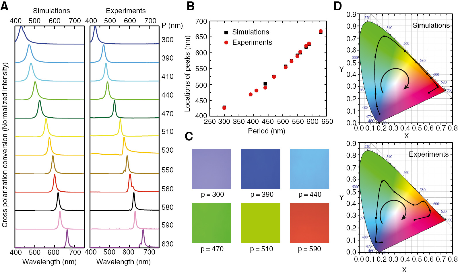
(A) Simulated and experimentally measured reflectively cross-polarized spectra of the PSG when the period varies from 300 to 630 nm. All the values are normalized to their respective maxima. (B) Reflective peak locations of the simulated (black squares) and measured (red circles) results shown in (A). (C) Experimental images of the colors captured by the CCD camera. A broad palette of color with high contrasts is realized. (D) Chromatic coordinates in the CIE 1931 diagram obtained from the simulated and measured spectra. Black arrows indicate the variable tendency according to the increasing of grating period.
To have a better understanding of the high-purity colors and tunable region, the corresponding chromatic coordinates are calculated and plotted in CIE 1931 chromaticity diagram as shown in Figure 2D [34]. For the simulated results in Figure 2A, all the corresponding chromatic coordinates are depicted as black dots located near the CIE boundary, which indicate the region of monochromatic colors. The chromatic coordinates for experimentally obtained spectra reasonably agree with their simulation counterparts. Slight variations can be understood by the fact that asymmetric reflection line shapes decrease the purity of colors [20]. Anyway, the color gamut in the CIE 1931 diagram achieved by this design is larger than that in many previous works [16], [17], [21].
Besides the realization of high-purity color filters, the feasibility of the high-resolution display of arbitrary chromatic patterns is investigated. As an example, three red characters “IOE” in a blue background are experimentally demonstrated. The logo fabricated by the nested interference lithography spans 30×30 mm, with a group of silver grooves exhibiting two periods: 600 nm for the red characters “IOE” and 400 nm for the blue background. Figure 3a and b shows the SEM images of the different periodic building blocks constituting characters and background, where the insets display zoom-in views of the arrays. Visually uniform dense line-patterns imply that this PSG can be readily applied in high-resolution chromatic display. The reflective cross-polarization photographs taken for incident light polarized at 45° are shown in Figure 3c. It can be seen that a bright red “IOE” sharply contrasts the blue background. Furthermore, the two distinct colors are still observed even at the corners and edges of the logo.
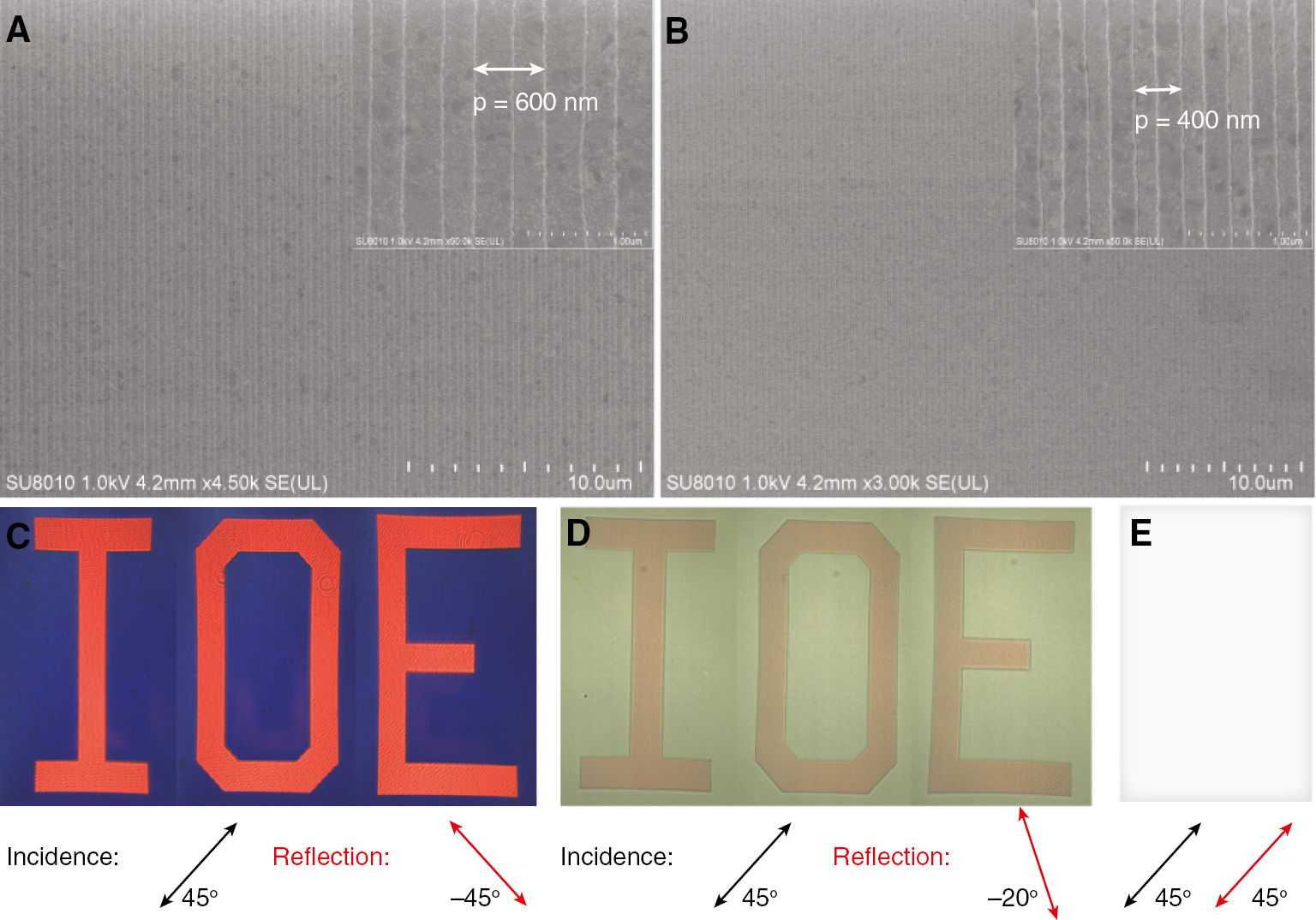
SEM images of the building blocks for the logo with period of (A) 600 nm and (B) 400 nm. (C–E) Microscopic images of the sample for 45° polarized incident light. The polarization direction of the reflection light is (C) −45°, (D) −20°, and (E) 45°.
Subsequently, we experimentally demonstrated the use of such PSG to create encrypted colors and switch from visible to invisible depending on the reflective polarization state. When rotating the linear polarizer in front of the CCD camera to polarize the reflective light at −20° with respect to the grooves, a dim red acronym “IOE” and green background emerge as depicted in Figure 3d. Figure 3e indicates that all the colors vanish when the reflective light and incident light possess the same polarization state. The sample looks white and maps to the central point in the CIE 1931 diagram. These fascinating phenomena offer platforms for security or encryption applications. The encrypted information recorded in the PSG can be only unscrambled by a couple of specific incident polarization and/or reflective helicity. In addition, PSG composed of silver makes the security tags or encrypted information readily disappear by natural oxidation, presenting a difficult-to-reuse guarantee and enhancing the safety.
To explore the physical mechanism inside the spin restoration for CP light or cross-polarization conversion for 45° polarized LP wave, the reflective amplitude and phase difference between two LP components along the x and y directions are calculated as depicted in Figure 4A. For a 1D PSG with period of 400 nm illuminated by a normally incident LP light with a polarization angle of 45°, the reflective amplitude of the x-component electric field remains flat, whereas the y-component spectra line undergoes a dip at a wavelength of 474 nm. Interestingly, the blue curve in the inset spectrum reaches a sharp peak at the same wavelength, which indicates that a phase difference of 180° is achieved between the orthogonal linear polarizations (|Φx−Φy|=180°). This result agrees well with the conclusions in previous works [29], [31], [35], which is also a requirement to reflect a CP light to its copolarization state at normal incidence.
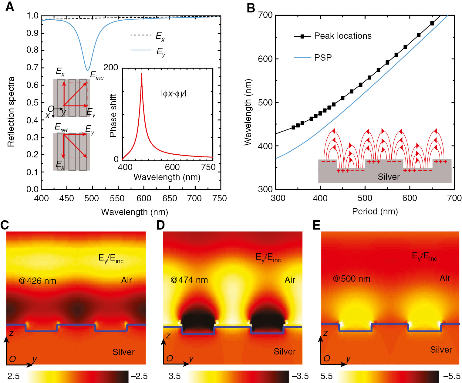
(A) Reflective spectral amplitudes for x- and y-polarized waves. The inset shows the calculated phase difference between the two orthogonal polarizations. (B) Comparison between the reflective peaks and PSP resonant wavelengths corresponding to variable grating periods. The inset depicts the collective oscillation of free electrons at the silver-air interface. (C–E) 2D color maps of the electric field (Ey) distribution with a period of 400 nm at (C) λ=426 nm, (D) λ=474 nm, and (E) λ=500 nm.
Subsequently, we analyzed the electromagnetic response of the PSG with the help of the commercial software CST MWS and get a visualization of the plasmonic resonance by the analytic PSP dispersion equation [12], [20]:
where λPSP is the vacuum wavelength, p is the period of the PSG and equal to the effective wavelength for PSP, and εd and εm are the dielectric functions of the air and silver, respectively. As plotted in Figure 4B, the blue curve corresponding to the PSP dispersion nearly overlaps the calculated peak locations, which signifies that PSP resonance dominates the spin restoration. The less-than-ideal superposition may result from the LSP tightly confined at the edges of the grooves, which alters the dispersion diagram of the surface plasmons. In fact, Equation (1) is only correct when the shallow grating does not change the propagation constant of PSP.
In an effort to get a clear visualization of the contributions made by the plasmonic resonances, the electric field distributions at the vertical cross-section with a period of 400 nm are plotted in Figure 4C–E, where the field amplitudes (Ey) are normalized to the incident magnitude (Einc) at the wavelengths of 426, 474, and 500 nm, respectively. As depicted in Figure 4C and D, the electric field is obviously enhanced at the silver-air interface and coupled with that in the adjacent elements, which verifies the excitation of the PSP resonance. Such field distribution owes to the collective oscillation of free electrons excited by the incident electromagnetic wave as described in the inset of Figure 4B. However, Figure 4E shows that the reinforced electromagnetic fields mainly locate at the corners and sidewalls of the silver groove, which is a feature of the LSP mode as introduced in a previous work [36]. It can be considered that both PSP and LSP contribute collectively to induce the 180° phase difference between the orthogonally linear polarization components. Loss in silver diminishes the reflective y-component electric field as shown in Figure 4A, resulting in the imperfect cross-polarization conversion.
In the case of the red color filter (P=630 nm), the quality factor (Q=λ/Δλ) of the hybrid plasmon resonance can achieve 41 nm, where the corresponding FWHM of the reflective peak is only 16 nm. As a result, such PSG color filter possesses a conspicuous spectral sensitivity to changes in the ambient environment [6], [37], [38]. We demonstrated this by fabricating three PSGs with the same period of 300 nm and coating these samples with different dielectric layers with a thickness of 35 nm as shown in Figure 5A. Interestingly, the blue color filtered out by the linear polarizer has been changed to azure when the dielectric environment varies from magnesium fluoride (MgF2; n=1.38) to silicon dioxide (SiO2; n=1.46). When the PSG is coated by poly(methyl methacrylate) (PMMA; n=1.55), a green color is generated, which is quite distinct from both the blue and azure cases as shown in Figure 5B. Our PSG theoretically paves the road toward observations of a sensitive refractive index change on the level of 0.01. We assumed that the PSG is originally immersed in water (n=1.33) and some other solutions gradually interfuse the environment to induce an increment of the refractive index. Remarkably, a relatively small refractive index change from 1.34 to 1.45 with a step of 0.01 in dielectric property results in an obviously continuous change of the scattered colors from green to yellow. Figure 5C depicts the various colors that can be easily distinguished by our naked eyes. It has shown promising features that the PSG can serve as an ultrasensitive liquid sensor (see Figure S3 for more colors in the CIE 1931 diagram).
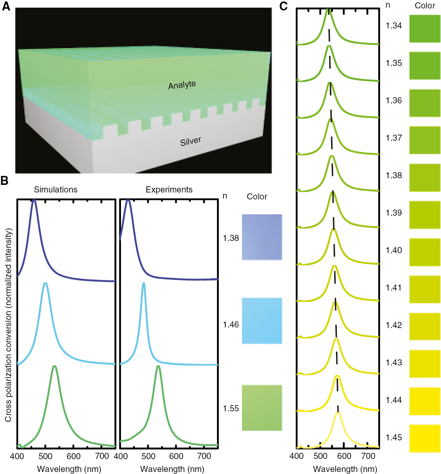
Color sensing and detection of the refractive index by tuning the resonant wavelength. (A) Schematic of the simple fluid solution detector used for refractive index sensing. (B) Simulated and experimental spectra of the PSG coated by MgF2 (n=1.38), SiO2 (n=1.46), and PMMA (n=1.55). The experimentally measured colorimetric responses of the PSG are depicted at the right of the experimental spectra. (C) Calculated cross-polarized reflection spectra of the PSG when the environmental refractive index varies from 1.34 to 1.45 nm. The corresponding colorimetric responses locate at the right side. All the values are normalized to their respective maxima.
Hybrid plasmon resonance exhibits a remarkable red shift with the increasing refractive index of the local dielectric environment. To evaluate the performance of the chromatic sensing, the sensitivity (S) is described as a peak shift per unit index change and the corresponding figure of merit (FOM) has been defined as below:
where λres is the resonant wavelength, ns is the refractive index of the local dielectric environment, and Δλ is the FWHM of the reflective peak. According to the measured data in Figure 5B, S=~700 and FOM=~14 are obtained.
In summary, we designed and experimentally demonstrated a novel color filter with a broad palette of RGB colors by employing photon spin restoration. The proposed devices exhibit high-efficiency output (~75%) at a specific wavelength and highly suppressed efficiency at off-resonance wavelengths. Spin-restored colors induced by sharp resonance (FWHM of ~16 nm) can be continuously modified for security or encryption applications. Moreover, the positions of the reflective peaks can be tuned by the ambient environment, which enables the development of colorimetric sensors. Minute changes in the local dielectric property of the PSG can be readily visualized and a sensitivity of ~700 nm/RIU has been experimentally obtained. Such a unique color filter combines a number of advantages in terms of the resonant bandwidth, peak intensity, fabrication easiness, and flexible tunability, which may find wide applications in color display, chromatic encryption, and biomedical sensing.
See Supplement 1 for the supporting content.
Funding source: National Natural Science Foundation of China
Award Identifier / Grant number: 61622508
Award Identifier / Grant number: 61575201
Funding statement: Funding: The 973 Program of China (2013CBA01700) and the National Natural Science Foundation of China (61622508 and 61575201).
Acknowledgments
We thank Dr. Jin for her help with the experiment.
References
[1] Barnes WL, Dereux A, Ebbesen TW. Surface plasmon subwavelength optics. Nature 2003;424:824–30.10.1038/nature01937Search in Google Scholar PubMed
[2] Pu M, Ma X, Li X, Guo Y, Luo X. Merging plasmonics and metamaterials by two-dimensional subwavelength structures. J Mater Chem C 2017;5:4361.10.1039/C7TC00440KSearch in Google Scholar
[3] Aydin K, Ferry VE, Briggs RM, Atwater HA. Broadband polarization-independent resonant light absorption using ultrathin plasmonic super absorbers. Nat Commun 2011;2:517.10.1038/ncomms1528Search in Google Scholar PubMed
[4] Pu M, Feng Q, Wang M, et al. Ultrathin broadband nearly perfect absorber with symmetrical coherent illumination. Opt Express 2012;20:2246–54.10.1364/OE.20.002246Search in Google Scholar PubMed
[5] Li W, Guler U, Kinsey N, et al. Refractory plasmonics with titanium nitride: broadband metamaterial absorber. Adv Mater 2014;26:7959–65.10.1002/adma.201401874Search in Google Scholar PubMed
[6] Li Z, Butun S, Aydin K. Ultranarrow band absorbers based on surface lattice resonances in nanostructured metal surfaces. ACS Nano 2014;8:8242–8.10.1021/nn502617tSearch in Google Scholar PubMed
[7] Ishii S, Shalaev VM, Kildishev AV. Holey-metal lenses: sieving single modes with proper phases. Nano Lett 2013;13:159–163.10.1021/nl303841nSearch in Google Scholar PubMed
[8] Gramotnev DK, Bozhevolnyi SI. Nanofocusing of electromagnetic radiation. Nat Photonics 2014;8:13–22.10.1038/nphoton.2013.232Search in Google Scholar
[9] Tang D, Wang C, Zhao Z, et al. Ultrabroadband superoscillatory lens composed by plasmonic metasurfaces for subdiffraction light focusing. Laser Photonics Rev 2015;9:713–9.10.1002/lpor.201500182Search in Google Scholar
[10] Song M, Wang C, Zhao Z, et al. Nanofocusing beyond the near-field diffraction limit via plasmonic Fano resonance. Nanoscale 2016;8:1635–41.10.1039/C5NR06504FSearch in Google Scholar PubMed
[11] Pendry JB. Negative refraction makes a perfect lens. Phys Rev Lett 2000;85:3966–9.10.1103/PhysRevLett.85.3966Search in Google Scholar PubMed
[12] Luo X, Ishihara T. Surface plasmon resonant interference nanolithography technique. Appl Phys Lett 2004;84:4780–2.10.1063/1.1760221Search in Google Scholar
[13] Xiao S, Drachev VP, Kildishev AV, et al. Loss-free and active optical negative-index metamaterials. Nature 2010;466:735–8.10.1038/nature09278Search in Google Scholar PubMed
[14] Genet C, Ebbesen TW. Light in tiny holes. Nature 2007;445:39–46.10.1038/nature05350Search in Google Scholar PubMed
[15] Kinoshita S, Yoshioka S, Miyazaki J. Physics of structural colors. Rep Prog Phys 2008;71:76401.10.1088/0034-4885/71/7/076401Search in Google Scholar
[16] Xu T, Wu Y-K, Luo X, Guo LJ. Plasmonic nanoresonators for high-resolution colour filtering and spectral imaging. Nat Commun 2010;1:59.10.1038/ncomms1058Search in Google Scholar PubMed
[17] Kaplan AF, Xu T, Guo LJ. High efficiency resonance-based spectrum filters with tunable transmission bandwidth fabricated using nanoimprint lithography. Appl Phys Lett 2011;99:143111.10.1063/1.3647633Search in Google Scholar
[18] Kumar K, Duan H, Hegde RS, Koh SCW, Wei JN, Yang JKW. Printing colour at the optical diffraction limit. Nat Nanotechnol 2012;7:557–61.10.1038/nnano.2012.128Search in Google Scholar PubMed
[19] Hong J, Chan E, Chang T, et al. Continuous color reflective displays using interferometric absorption. Optica 2015;2:589–97.10.1364/OPTICA.2.000589Search in Google Scholar
[20] Shrestha VR, Lee S-S, Kim E-S, Choi D-Y. Aluminum plasmonics based highly transmissive polarization-independent subtractive color filters exploiting a nanopatch array. Nano Lett 2014;14:6672–8.10.1021/nl503353zSearch in Google Scholar PubMed
[21] Shen Y, Rinnerbauer V, Wang I, Stelmakh V, Joannopoulos JD, Soljačić M. Structural colors from Fano resonances. ACS Photonics 2015;2:27–32.10.1021/ph500400wSearch in Google Scholar
[22] Kats MA, Capasso F. Optical absorbers based on strong interference in ultra-thin films. Laser Photonics Rev 2016;10:735–49.10.1002/lpor.201600098Search in Google Scholar
[23] Wang J, Fan Q, Zhang S, et al. Ultra-thin plasmonic color filters incorporating free-standing resonant membrane waveguides with high transmission efficiency. Appl Phys Lett 2017;110:31110.10.1063/1.4974455Search in Google Scholar
[24] Xu T, Walter EC, Agrawal A, et al. High-contrast and fast electrochromic switching enabled by plasmonics. Nat Commun 2016;7:10479.10.1038/ncomms10479Search in Google Scholar PubMed PubMed Central
[25] Li X, Chen L, Li Y, et al. Multicolor 3D meta-holography by broadband plasmonic modulation. Sci Adv 2016;2:e1601102.10.1126/sciadv.1601102Search in Google Scholar PubMed PubMed Central
[26] Liang G, Wang C, Zhao Z, et al. Squeezing bulk plasmon polaritons through hyperbolic metamaterial for large area deep subwavelength interference lithography. Adv Opt Mater 2015;3:1248–56.10.1002/adom.201400596Search in Google Scholar
[27] Luo X. Principles of electromagnetic waves in metasurfaces. Sci China-Phys Mech Astron 2015;58:594201.10.1007/s11433-015-5688-1Search in Google Scholar
[28] Pu M, Chen P, Wang Y, et al. Anisotropic meta-mirror for achromatic electromagnetic polarization manipulation. Appl Phys Lett 2013;102:131906.10.1063/1.4799162Search in Google Scholar
[29] Grady NK, Heyes JE, Chowdhury DR, et al. Terahertz metamaterials for linear polarization conversion and anomalous refraction. Science 2013;340:1304–7.10.1126/science.1235399Search in Google Scholar PubMed
[30] Shaltout A, Liu J, Kildishev A, Shalaev V. Photonic spin Hall effect in gap-plasmon metasurfaces for on-chip chiroptical spectroscopy. Optica 2015;2:860–3.10.1364/OPTICA.2.000860Search in Google Scholar
[31] Xiao S, Mühlenbernd H, Li G, et al. Helicity-preserving omnidirectional plasmonic mirror. Adv Opt Mater 2016;4:654–8.10.1002/adom.201500705Search in Google Scholar
[32] Johnson PB, Christy RW. Optical constants of the noble metals. Phys Rev B 1972;6:4370–9.10.1103/PhysRevB.6.4370Search in Google Scholar
[33] Zhu X, Zhang Y, Zhang J, et al. Ultrafine and smooth full metal nanostructures for plasmonics. Adv Mater 2010;22:4345–9.10.1002/adma.201001313Search in Google Scholar PubMed
[34] Smith T, Guild J. The C.I.E. colorimetric standards and their use. Trans Opt Soc 1931;33:73.10.1088/1475-4878/33/3/301Search in Google Scholar
[35] Guo Y, Wang Y, Pu M, et al. Dispersion management of anisotropic metamirror for super-octave bandwidth polarization conversion. Sci Rep 2015;5:8434.10.1038/srep08434Search in Google Scholar PubMed PubMed Central
[36] Sherry LJ, Chang S, Schatz GC, Van Duyne RP, Wiley BJ, Xia Y. Localized surface plasmon resonance spectroscopy of single silver nanocubes. Nano Lett 2005;5:2034–8.10.1021/nl0515753Search in Google Scholar PubMed
[37] Liu N, Mesch M, Weiss T, Hentschel M, Giessen H. Infrared perfect absorber and its application as plasmonic sensor. Nano Lett 2010;10:2342–8.10.1021/nl9041033Search in Google Scholar PubMed
[38] King NS, Liu L, Yang X, et al. Fano resonant aluminum nanoclusters for plasmonic colorimetric sensing. ACS Nano 2015;9:10628–36.10.1021/acsnano.5b04864Search in Google Scholar PubMed
Supplemental Material:
The online version of this article offers supplementary material (https://doi.org/10.1515/nanoph-2017-0062).
©2017 Xiangang Luo et al., published by De Gruyter, Berlin/Boston
This work is licensed under the Creative Commons Attribution-NonCommercial-NoDerivatives 4.0 License.
Articles in the same Issue
- Review articles
- Advances in optoplasmonic sensors – combining optical nano/microcavities and photonic crystals with plasmonic nanostructures and nanoparticles
- Periodic array-based substrates for surface-enhanced infrared spectroscopy
- From isolated light-harvesting complexes to the thylakoid membrane: a single-molecule perspective
- Theory and applications of toroidal moments in electrodynamics: their emergence, characteristics, and technological relevance
- Multiple exciton generation in quantum dot-based solar cells
- All-integrated terahertz modulators
- Exciton-plasmon coupling interactions: from principle to applications
- Emerging technologies for high performance infrared detectors
- Research articles
- Magneto-optical response in bimetallic metamaterials
- Saturated evanescent-wave absorption of few-layer graphene-covered side-polished single-mode fiber for all-optical switching
- Reversible thermochromic response based on photonic crystal structure in butterfly wing
- Selection rule engineering of forbidden transitions of a hydrogen atom near a nanogap
- Heterogeneous terahertz quantum cascade lasers exceeding 1.9 THz spectral bandwidth and featuring dual comb operation
- Effect of temperature on the structural, linear, and nonlinear optical properties of MgO-doped graphene oxide nanocomposites
- Engineering light emission of two-dimensional materials in both the weak and strong coupling regimes
- Anisotropic excitation of surface plasmon polaritons on a metal film by a scattering-type scanning near-field microscope with a non-rotationally-symmetric probe tip
- Achieving pattern uniformity in plasmonic lithography by spatial frequency selection
- Controllable all-fiber generation/conversion of circularly polarized orbital angular momentum beams using long period fiber gratings
- High-efficiency/CRI/color stability warm white organic light-emitting diodes by incorporating ultrathin phosphorescence layers in a blue fluorescence layer
- Relative merits of phononics vs. plasmonics: the energy balance approach
- Efficiency enhancement of InGaN amber MQWs using nanopillar structures
- Color display and encryption with a plasmonic polarizing metamirror
- Experimental demonstration of an optical Feynman gate for reversible logic operation using silicon micro-ring resonators
- Specialized directional beaming through a metalens and a typical application
- Anomalous extinction in index-matched terahertz nanogaps