Key considerations for preparing ion-milled lithium metal cross-sectional samples
-
Yulia Trenikhina

 and
Stephen T. Kelly
and
Stephen T. Kelly

Abstract
Detailed understanding of lithium anode morphology is essential for solid-state battery technology development. Non-optimal interfacial contacts and structural changes during cycling present significant challenges, limiting both battery performance and wide adoption of solid-state batteries. Cross-sectional sample preparation combined with advanced electron microscopy techniques provides essential insights into the internal microstructure and composition of materials, particularly at critical interfaces. Visualizing degradation is crucial for identifying failure mechanisms and optimizing material performance. This paper explores the temperature dependence of ion-polished cross-sections, offers detailed guidelines for lithium cross-section preparation using a Ga+ Focused Ion Beam Scanning Electron Microscope (FIB-SEM) system, and compares the results to cross-sections prepared with an Ar+ ion polisher. We demonstrate that artifacts introduced during lithium cross-sectioning at room temperature can be eliminated by conducting the preparation at cryogenic temperatures of −100 °C or lower, regardless of the type of ions used in the sputtering process. This guidance helps ensure researchers generate quality cross-sections when evaluating this important field.
1 Introduction
Lithium anodes hold significant potential for advancing solid-state battery (SSB) technology. With a high gravimetric capacity of 3,860 mA h/g, lithium enables lightweight and compact battery designs, far surpassing traditional lithium-ion batteries with graphite anodes (372 mA h/g gravimetric capacity). Additionally, SSBs promise enhanced safety through the replacement of flammable liquid electrolytes with non-flammable solid-state electrolytes (SSE), as well as improved thermal stability and longer lifespans. However, in practical conditions, limited electrochemical performance – such as rapid capacity fading over insufficient cycles – continues to hinder SSBs.
To unlock the theoretical potential of SSBs, it is critical to link performance degradation to specific physio-chemical processes occurring within the battery and to identify the underlying mechanisms driving electrochemical decline. In SSBs, charge transfer efficiency is highly dependent on the interfacial contact between active material and the SSE. Maintaining optimal contact and minimizing contact resistance throughout battery cycling is particularly challenging due to volumetric changes in the electrode during the charge-discharge process. Poor physical contact between the active material and the SSE reduces charge transfer efficiency, leading to capacity loss. Furthermore, localized current at limited contact points can promote dendrite growth, increasing the risk of short-circuiting and raising safety concerns [1].
Visualization and quantitative assessment of morphological changes at the microscale within SSB electrodes is crucial for understanding the mechanisms that define battery performance [2]. Advanced electron microscopy techniques, such as 2D cross-sectioning and 3D tomography, enable detailed analysis of electrode morphology (porosity, tortuosity, and the components microstructure) [3], [4], [5].
Preserving the original morphology of the sample without introducing artifacts – whether from air exposure or sample preparation methods – is vital for accurate root-cause analysis [6], [7]. The air sensitivity of SSB components, particularly lithium anodes and SSEs, rules out most conventional metallographic methods that rely on mechanical processing. Conventional mechanical polishing typically involves the use of abrasive, water-based polishing media and the application of pressure to the sample surface. However, these conditions are unsuitable for lithium metal due to its highly reactive nature, which leads to vigorous exothermic reactions with water. Electropolishing, while effective for electrically conductive materials, is not ideal for lithium as it often results in surface residues after the process. Similarly, the cleaving method, which relies on controlled fracturing, is ineffective for lithium due to its soft and ductile properties.
Focused-Ion Beam – Scanning Electron Microscopy (FIB-SEM) systems [3], [5], [8] and stand-alone ion polishing tools [9], [10], [11], [12] have been proven effective in addressing the air and temperature sensitivity of lithium and solid-state battery components, ensuring sample integrity during analysis. Although Argon ion polishing systems lack precise control over the cross-section location, they offer environmental control (e.g., air-free sample transfer) and temperature regulation during cross-section preparation. In contrast, FIB-SEM systems leverage the full capabilities of SEM and SEM-based techniques, such as Energy Dispersive Spectroscopy (EDS) and Electron Backscatter Diffraction (EBSD), while enabling on-demand, site-specific cross-section preparation and tomography.
The importance of cryogenic temperature cross-sectional preparation for investigating anode and cathode interfaces with solid-state electrolytes has been highlighted in the literature [8], [13]. For lithium cross-sectioning using Ga+ FIB-SEM, a cryogenic temperature of −170 °C has been recommended [8]. Similarly, recent studies utilizing Xe + PFIB for lithium cross-sectioning emphasize the necessity of cryogenic temperatures, with −100 °C being identified as sufficient [14], [15].
In our work, we explored a range of temperatures for lithium cross-sectional preparation using Ga+ FIB-SEM system. Cryogenic conditions are indeed essential to prevent local heating, which can induce morphological changes and void formation in lithium. However, our findings demonstrate that a cryogenic temperature of −100 °C is as effective as −160 °C for lithium cross-sectional preparation with Ga+ FIB-SEM.
2 Materials and methods
The Zeiss Cryo Crossbeam 550, equipped with the Quorum PP3010Z system, was used for FIB-SEM analysis. Lithium samples (Goodfellow, 200 µm thick, 99.9 % purity) were transferred from an argon-filled glovebox to the Cryo Crossbeam 550 under vacuum using the Quorum Inert Transfer Shuttle. The shuttle was connected to the glovebox via an interface that functions as an air lock (Figure 1A). Once transported to the microscope under vacuum, the samples were introduced into the Cryo Crossbeam 550 via Quorum preparation chamber, which is designed to accommodate the shuttle (Figure 1B). Finally, the samples were transferred to the Quorum stage in the microscope’s main chamber, where cooling capabilities were utilized for further analysis.

Quorum inert transfer shuttle attached to: (A) glovebox interface, (B) preparation chamber on Cryo Crossbeam 550.
Upon arrival, platinum or carbon protective layers were deposited with the FIB from organometallic precursors to create several sites for future cross-sections before initiating the cooling process. The deposition of platinum or carbon protective layers at room temperature was chosen for this study to demonstrate the capability for detailed surface examination prior to cross-section analysis. Moderate FIB currents were used for the deposition to limit any potential surface damage or modification. While protective layer deposition at cryogenic temperatures is possible, it would create a “blanket” layer on the entire sample surface. Therefore, surface image information that might guide further cross-section preparation would be lost. The Table 1 below summarizes the experimental parameters used at both room and cryogenic temperatures. For the bulk removal and final cleaning steps, 1 µm-depth-Silicon recipe was used with the following parameters: pixel spacing = 5 %, track spacing = 5 %, bidirectional scanning, the other parameters are specified in the table for the specific recipe. For the trapezoid bulk removal shape, the length of the trapezoid short base is specified. For the Recipes 1A, 1B and 2, target depth was set to 15 µm. Recipe 3 was set to the target depth of 30 µm.
Ga+ FIB parameters.
| Recipe | Step 1 Protective layer at 24 °C | Step 2 Bulk removal | Step 3 Final cleaning |
|---|---|---|---|
| Recipe 1A small cross-section | Pt deposition 15 × 4 × 0.7 µm 30 kV 100 pA | Trapezoid trench 20 µm 30 kV 30 nA dose = 3,000 mC/cm2 dwell = 49 µs 10 loops | Cross section 20 × 5 µm 30 kV 3 nA dose = 3,000 mC/cm2 dwell = 264 µs |
| Recipe 1B small cross-section | Pt deposition 15 × 4 × 0.7 µm 30 kV 100 pA | Trapezoid trench 20 µm 30 kV 30 nA dose = 3,000 mC/cm2 dwell = 490 µs 1 loop | Cross section 20 × 5 µm 30 kV 3 nA dose = 3,000 mC/cm2 dwell = 264 µs |
| Recipe 2 medium cross-section | Pt or C deposition 25 × 4 × 0.7 µm 30 kV 100 pA | Trapezoid trench 30 µm 30 kV 65 nA dose = 6,000 mC/cm2 dwell = 46 µs 10 loops | Cross section 30 × 5 µm 30 kV 15 nA dose = 3,000 mC/cm2 dwell = 281 µs |
| Recipe 3 large cross-section | Pt deposition 80 × 4 × 0.7 µm 30 kV 300 pA | Trapezoid trench 90 µm 30 kV 65 nA dose = 6,000 mC/cm2 dwell = 31 µs 30 loops | Cross section 90 × 5 µm 30 kV 15 nA dose = 3,000 mC/cm2 dwell = 281 µs |
The Fischione SEM Mill 1061 argon ion polishing system was used to prepare cross-sectional samples of lithium. To ensure air-free transfer, the Fischione Inert Transfer Capsule was employed to move the lithium samples from the glovebox to the ion polishing system. In the glovebox, lithium pieces were mounted onto a titanium Fischione masks using a micrometer-assisted jig. The sample protrusion above the mask was maintained at and below 80 µm. To prepare a lithium cross-section, the Fischione SEM Mill 1061 cross-section recipe was run for 4 h at 8 kV accelerating voltage, 4° milling angle with 3 rpm using a single Ar + ion source. The cross-section alignment option was used.
3 Results
3.1 SSB components air-sensitivity
Lithium metal air-sensitivity was explored by SEM imaging of Lithium surface. Figure 2 illustrates the degradation of the lithium surface upon exposure to air. The morphological changes observed on the lithium surface are attributed to phase transformations.

Lithium surface (A) after a successful air-free transfer, (B) after 5 min in ambient atmosphere, (C) after 10 min in ambient atmosphere.
3.2 Cross-sectioning at room temperature
Recipe 1A was utilized to prepare a Lithium cross-section at room temperature. Figure 3 illustrates lithium surface before (Figure 3A) and after (Figure 3B) the deposition of a platinum protective layer, as well as following cross-section preparation at room temperature (Figure 3C). High contrast specks and two voids observed beneath the platinum protective layer are the result of the room-temperature cross-sectioning process. The formation of voids in lithium under such conditions had been previously reported [8], [13] and is not reflecting the initial state of the lithium surface.

Lithium surface (A) prior to platinum protective layer deposition, (B) after the deposition of platinum protective layer, (C) after cross-sectioning with Ga + FIB at room temperature using Recipe 1A.
Another example of Lithium cross-section prepared with Recipe 1B at room temperature (Figure 4) shows multiple void formations in the cross-section. Figure 4(B) shows high contrast specks in the cross-section face that indicate Lithium–Gallium alloying at room temperature.

Lithium surface (A) with protective layer deposition. (B) Cross-section prepared at this site at room temperature with Recipe 1B.
Recipe 1B was used at another location at room temperature and resulted in warping in the cross-section face (Figure 5A). An additional cleaning step with lower Ga+ FIB current only worsens the quality of Lithium cross section (Figure 5B).

Lithium cross-section prepared at room temperature (A) with 3 nA Ga + FIB current as a final step using Recipe 1B, (B) with an additional 1.5 nA Ga + FIB current cleaning.
3.3 Cross-sectioning at cryogenic temperature
To minimize artifacts during cross-section preparation caused by local temperature increases, cryogenic cooling is employed. It has been reported that artifact-free cross-section preparation at cryogenic temperatures enables both 2D and 3D studies of electrode microstructures, which are essential for practical battery design [8]. The platinum protective layer was deposited at room temperature (Figure 6A). Figure 6B and C show lithium cross-section prepared with Recipe 2 at T = −160 °C. The featureless lithium metal cross-section exhibits no signs of void formation, degradation or warping, which is consistent with previous reports. The cross-section was prepared using a 65 nA Ga+ FIB current and cleaned with a 15 nA current, with no additional lower-current cleaning required.

Lithium surface (A) with platinum deposition at room temperature. Lithium cross-section prepared at T = −160 °C with Recipe 2: (B) SE2 detector, (C) InLens detector.
Figure 7 presents a larger, artifact-free cross-section, 80 µm in length, prepared using a 65 nA current and cleaned with a 15 nA current (Recipe 3).
Lithium surface (A) with platinum deposition at room temperature. Lithium cross-section prepared at T = −160 °C with Recipe 3: (B) SE2 detector, (C) InLens detector.
To investigate the range of cryogenic temperatures suitable for high-quality lithium cross-section preparation, Figure 8 shows cross-sections prepared at T = −100 °C using Recipe 2. Both platinum and carbon protective layers were deposited at room temperature and subsequently tested. No degradation was observed on the cross-sectional faces, and no differences were noted between samples prepared at T = −160 °C and T = −100 °C.

Lithium cross-sections prepared at T = −100 °C using Recipe 2. Platinum protective layer: (A) SE2 detector, (B) InLens detector, (C) InLens detector at higher magnification. Carbon protective layer: (D) SE2 detector, (E) InLens detector, (F) InLens detector at higher magnification.
An attempt to prepare a lithium cross-section at T = −50 °C (Figure 9) was conducted with Recipe 2. However, artifacts (black and white spots) were observed on the cross-sectional faces of the prepared samples. The formation of these artifacts at T = −50 °C is attributed to an insufficiently low temperature to prevent Li–Ga alloying and potential morphological changes during the sputtering process. Cleaning at lower beam currents, such as 3 nA at this temperature introduced more degradation sites rather than improving cross-section quality.

Lithium cross section (A) prepared at T = −50 °C with Recipe 2, (B) at higher magnification with guiding annotations.
3.4 Lithium sample preparation with an ion polisher
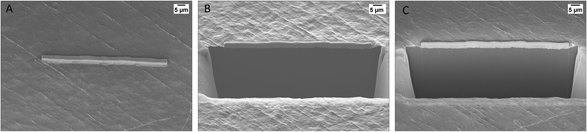
To evaluate the capabilities of the Argon ion polishing system for lithium cross-sectional preparation, two lithium samples were prepared with Fischione SEM Mill 1061 under different conditions. Figure 10(A) shows a lithium cross-section prepared at cryogenic temperatures, ranging from T = −135 °C to T = −153 °C. The resulting cross-sectional surface is clean and free of artifacts, distinctly different from the top surface of the sample. Notably, the cross-section reveals a grain boundary (marked by the arrows), providing evidence of successful and appropriate sample preparation.

Lithium cross sections prepared with the Fischione SEM Mill 1061 at (A) cryogenic temperature, and (B) room temperature.
In contrast, Figure 10(B) illustrates a lithium cross-section prepared at room temperature (T = 24 °C) without cryogenic cooling. The cross-section prepared under these conditions exhibits clear signs of melting, including edge rounding and the presence of small, round droplets on the cross-sectional surface. Additionally, surface warping leads to void formation and significant alteration of the sample’s microstructure.
4 Discussion
4.1 Air-sensitivity of SSB and its components
Most SSBs are air-sensitive due to reactions between the anode and the SSE with moisture and air [16], [17]. For instance, sulfide-based SSEs are highly sensitive to moisture because of hydrolysis. Moisture enables toxic gases production and degrades battery performance by reducing ionic conductivity. Additionally, air exposure alters surface properties, disrupting the contact between layers in SSB. The surface of lithium metal is known to change from silver to black upon exposure to air. This visible color change is attributed to phase transformations caused by the formation of lithium hydroxide, oxide, and carbonate on the surface. Preserving the original state of sample during the preparation, handling, and analysis is critical, as preparation artifacts can make root-cause analysis nearly impossible.
To address air sensitivity, proper sample handling is essential for both top-down surface investigations and cross-sectional studies. Most air-free workflows involve the use of a transfer shuttle. In these systems, users typically choose between rough vacuum or inert gas as the transfer medium. The shuttle is sealed with a separation valve, and no active pumping occurs during transit from the glovebox to the microscope.
The importance of proper sample handling for sensitive materials, such as SSB and its components, is demonstrated using the example of lithium metal. Our studies reveal significant morphological transformations when lithium is exposed to air (Figure 2). To preserve the original structure and chemistry of the battery materials under investigation, it is crucial to maintain an air-free environment at all times, including during transfer to the microscope.
4.2 Conditions for lithium cross-sectioning with Ga+ FIB-SEM
The preparation of lithium cross-sections was studied at different temperatures. Cross-sectional preparation at room temperature resulted in various artifacts, including void formation, alloying effects and warping on the cross-section face (Figures 3–5). Due to the low stopping power of lithium, gallium implantation occurs, leading to a localized temperature increase rather than effective material removal through the sputtering process [8]. Room-temperature ion sputtering techniques have been shown to cause melting and significant morphological changes in soft metals [18]. While the exact mechanism of void formation is not fully understood, studies on indium attribute it to the formation of an indium-gallium alloy, which lowers the eutectic temperature and causes the sample to melt. Void formation and significant morphological changes in lithium cross-sections prepared at room temperature have been reported in previous studies [8], [13]. Our findings confirm similar results using various cross-sectional preparation recipes and final step parameters. At room temperature, no artifact-free recipe for Ga+ FIB preparation was identified.
Compared to room temperature, lithium cross-sections prepared at cryogenic temperatures using Ga+ FIB demonstrate significantly higher quality, as reported in previous studies [8], [14], [19]. However, unlike earlier findings, our research shows that a temperature of −100 °C or lower is sufficient for artifact-free lithium cross-sectioning using Ga+ FIB. Although the exact reason for the discrepancy between our findings and previous studies is unclear, there are several potential explanations. One possibility is that the FIB-SEM system used in previous studies, which was from a different vendor, may have different FIB characteristics. Additionally, the exact recipe used in the earlier studies is unknown, but it is likely that their approach differs from our recipes.
Several recent studies [14], [15] have reported successful preparation of high-quality lithium cross-sections at T = −100 °C using Xe + plasma FIB (pFIB) instead of Ga+ FIB. These studies attribute success to the use of Xe + ions. However, our findings demonstrate that high-quality lithium cross-sections can also be achieved with Ga+ ions at the same temperature. This highlights the critical role of cryogenic temperature in sample preparation, rather than the specific type of ion used for sputtering.
4.3 Lithium cross-sectioning by the ion polisher
Lithium cross-sections were prepared at both room temperature and cryogenic temperatures using an ion polisher with Argon ions for effective sputtering. Similar to cross-sections prepared with Ga+ FIB, those prepared at room temperature exhibited noticeable preparation artifact, including warping, void formation, and melting (Figure 10B). In contrast, cross-sections prepared at cryogenic temperatures ranging from −135 °C to −153 °C showed clean, high-quality results without artifact (Figure 10A).
These findings demonstrate that artifact-free Lithium cross-sections can be achieved using high-current Argon ions (in the hundred µA range) at temperatures of −135 °C or lower. This highlights the critical role of cryogenic temperatures in Lithium sample preparation with Ar ion polishing. An additional study exploring higher temperatures during lithium cross-sectioning would be beneficial for identifying the threshold temperature suitable for this experiment.
5 Conclusions
In this study, we confirmed the critical role of cryogenic temperatures in the preparation of high-quality lithium cross-sections with Ga+ FIB-SEM system. We explored air-free transfer conditions of lithium samples from the glovebox to the microscope for successful, artifact-free surface analysis.
Cross-sectioning lithium at cryogenic temperatures (T = −160 °C and T = −100 °C) resulted in clean, artifact-free cross-sections, even at high milling currents, with no observable degradation. Comparable results were achieved at both temperatures using a 65 nA current for trench milling and a 15 nA current for cleaning, indicating that T = −100 °C is a viable alternative to T = −160 °C. However, attempts to prepare cross-sections at T = −50 °C showed degraded results indicating Li–Ga alloying and void formation on the cross-sectional face. These findings highlight the necessity of cryogenic cooling for artifact-free lithium cross-section preparation.
We expanded our study on the effect of cryogenic temperatures for the lithium cross-sections preparation by employing an Ar + ion polisher. Lithium cross-sections prepared at cryogenic temperatures of −135 °C and below are of high quality and free from artifacts, in contrast to those prepared at room temperature.
A detailed investigation of lithium cross-sections prepared at −100 °C and below with either Ga+ FIB-SEM or Ar + ion polisher confirms the production of high-quality, artifact-free cross-sections. Therefore, our findings suggest that the critical parameter for achieving artifact-free cross-sections with ion polishing, regardless of the ion species, is maintaining a sample temperature of −100 °C or lower during cross-section preparation. This guidance helps ensure researchers generate quality, meaningful cross-sections when evaluating this important field.
Acknowledgments
We would like to express our gratitude to Dr. Heiko Stegmann for his valuable insights and constructive discussions.
-
Research ethics: Not applicable.
-
Informed consent: Not applicable.
-
Author contributions: All authors have accepted responsibility for the entire content of this manuscript and approved its submission.
-
Use of Large Language Models, AI and Machine Learning Tools: None declared.
-
Conflict of interest: The authors state no conflict of interest.
-
Research funding: None declared.
-
Data availability: Not applicable.
References
[1] R. Chen, Q. Li, X. Yu, L. Chen, and H. Li, “Approaching practically accessible solid-state batteries: stability issues related to solid electrolytes and interfaces,” Chem. Rev., vol. 120, no. 14, pp. 6820–6877, 2020. https://doi.org/10.1021/acs.chemrev.9b00268.Search in Google Scholar PubMed
[2] S. Lou, Z. Yu, Q. Liu, H. Wang, M. Chen, and J. Wang, “Multi-scale imaging of solid-state battery interfaces: from atomic scale to macroscopic scale,” Chem, vol. 6, no. 9, pp. 2199–2218, 2020. https://doi.org/10.1016/j.chempr.2020.06.030.Search in Google Scholar
[3] F. Mura, F. Cognigni, M. Ferroni, V. Morandi, and M. Rossi, “Advances in focused ion beam tomography for three-dimensional characterization in materials science,” Materials, vol. 16, no. 17, p. 5808, 2023. https://doi.org/10.3390/ma16175808.Search in Google Scholar PubMed PubMed Central
[4] M. Motoyama, “In situ microscopy techniques for understanding Li plating and stripping in solid-state batteries,” Microscopy, vol. 73, no. 2, pp. 184–195, 2024. https://doi.org/10.1093/jmicro/dfad058.Search in Google Scholar PubMed
[5] M. Zhang et al.., “Coupling of multiscale imaging analysis and computational modeling for understanding thick cathode degradation mechanisms,” Joule, vol. 7, no. 1, pp. 201–220, 2023. https://doi.org/10.1016/j.joule.2022.12.001.Search in Google Scholar
[6] H. Zhou et al.., “SEM characterization technique for air-sensitive all-solid-state lithium battery materials,” Ultramicroscopy, vol. 276, 2025, Art. no. 114194. https://doi.org/10.1016/j.ultramic.2025.114194.Search in Google Scholar PubMed
[7] L. Cheng et al.., “The origin of high electrolyte-electrode interfacial resistances in lithium cells containing garnet type solid electrolytes,” Phys. Chem. Chem. Phys., vol. 16, no. 34, pp. 18294–18300, 2014. https://doi.org/10.1039/C4CP02921F.Search in Google Scholar
[8] J. Z. Lee et al.., “Cryogenic focused ion beam characterization of lithium metal anodes,” Energy Lett., vol. 4, no. 2, 2019. https://doi.org/10.1021/acsenergylett.8b02381.Search in Google Scholar
[9] P. Nowakowski, C. Bonifacio, M. Ray, and P. Fischione, “Developments in broad ion beam milling sample preparation instrumentation for microscopy and microanalysis applications,” Microsc. Microanal., vol. 29, no. suppl 1, pp. 2075–2076, 2023. https://doi.org/10.1093/micmic/ozad067.1074.Search in Google Scholar
[10] C. Chen et al.., “Equipment development for characterization of microstructural evolution and 3D reconstruction of lithium-ion battery electrodes based on broad ion beam-scanning electron microscopy (BIB-SEM),” J. Power Sources, vol. 646, 2025, Art. no. 237244. https://doi.org/10.1016/j.jpowsour.2025.237244.Search in Google Scholar
[11] J. Kim, Y. W. Jeong, H. Y. Cho, and H. J. Chang, “Alternative sample preparation method for large-area cross-section view observation of lithium ion battery,” Appl. Microsc., vol. 47, no. 2, pp. 77–83, 2017. https://doi.org/10.9729/AM.2017.47.2.77.Search in Google Scholar
[12] S. Jaiser et al.., “Microstructure formation of lithium-ion battery electrodes during drying – an ex-situ study using cryogenic broad ion beam slope-cutting and scanning electron microscopy (Cryo-BIB-SEM),” J. Power Sources, vol. 345, pp. 97–107, 2017. https://doi.org/10.1016/j.jpowsour.2017.01.117.Search in Google Scholar
[13] M. J. Zachman, Z. Tu, L. A. Archer, and L. F. Kourkoutis, “Nanoscale elemental mapping of intact solid–liquid interfaces and reactive materials in energy devices enabled by Cryo-FIB/SEM,” ACS Energy Lett., vol. 5, no. 4, pp. 1224–1232, 2020. https://doi.org/10.1021/acsenergylett.0c00202.Search in Google Scholar
[14] Y. Peng and K. Nishikawa, “Three-dimensional imaging of the microstructure of lithium metal anode using Xenon plasma focused ion beam,” Cell Rep. Phys. Sci., vol. 6, no. 2, 2025, Art. no. 102439. https://doi.org/10.1016/j.xcrp.2025.102439.Search in Google Scholar
[15] S. Bai et al.., “Guidelines for correlative imaging and analysis of reactive lithium metal battery materials,” arXiv:2412.19376, 2024. https://doi.org/10.48550/arXiv.2412.19376.Search in Google Scholar
[16] H. Tsukasaki, H. Sano, Y. Morino, and S. Mori, “Deterioration mechanisms during exposure to humidity-controlled air of argyrodite solid electrolytes for all-solid-state batteries,” Microsc. Microanal., vol. 28, no. S1, pp. 338–339, 2022. https://doi.org/10.1017/S1431927622002112.Search in Google Scholar
[17] T. Liu, L. W. Kum, D. K. Singh, and J. Kumar, “Thermal, electrical, and environmental safeties of sulfide electrolyte-based all-solid-state Li-Ion batteries,” ACS Omega, vol. 8, no. 13, pp. 12411–12417, 2023. https://doi.org/10.1021/acsomega.3c00261.Search in Google Scholar PubMed PubMed Central
[18] H. Stegmann and J. Derakhshandeh, “Cryo-FIB solution comparison for characterization of indium microbond structures,” Microsc. Microanal., vol. 30, no. S1, 2024. https://doi.org/10.1093/mam/ozae044.613.Search in Google Scholar
[19] D. Cheng, B. Lu, G. Raghavendran, M. Zhang, and Y. S. Meng, “Leveraging cryogenic electron microscopy for advancing battery design,” Matter, vol. 5, no. 1, pp. 26–42, 2022. https://doi.org/10.1016/j.matt.2021.11.019.Search in Google Scholar
Supplementary Material
This article contains supplementary material (https://doi.org/10.1515/mim-2025-0024).
© 2025 the author(s), published by De Gruyter on behalf of Thoss Media
This work is licensed under the Creative Commons Attribution 4.0 International License.