Abstract
We have studied distributed Raman amplification (DRA) and hybrid Raman amplification to apply both 10G-EPON and TWDM-PON systems. Two types of access networks, 50 km and 10 km, are assumed for case studies. Using the calculated optical received signal power Ps and optical signal noise ratio (OSNR), we consider the cases where the hybrid Raman amplification is necessary or not. In the case of coexistence of both systems, co-use of lumped Raman amplification (LRA) located at a central office (CO) may be possible. The co-use of LRA for both systems is discussed using the calculated Ps and OSNR.
1 Introduction
Passive optical networks, such as EPON, G-PON, 10G-EPON, XG-PON, are considered to construct access networks economically. To meet the demands of data traffic increase, the next-generation PON systems with 40 Gbps, TWDM-PON, have been extensively discussed [1, 2]. The important issues are higher bit rate, larger splitting number and longer transmission distance for upgrading the existing PON systems. Eight signal wavelengths will be used in TWDM-PON systems. Economical and smooth migrations are important issues of upgrading to the TWDM-PON systems. There may be the case of coexistence of both 10G-EPON and TWDM-PON systems in a transient stage from 10G-EPON systems to the full use of TWDM-PON systems.
In previous papers [3–6], we have proposed and investigated two types of upgrading methods, distributed Raman amplification (DRA) and the hybrid Raman amplification. The latter uses DRA, lumped Raman amplification (LRA) and EDFA (Er-doped fiber amplifier). We think the Raman and hybrid Raman amplifications are suitable for passive optical networks because they are basically composed of fiber-based optical components and there are no active components in transmission lines. Therefore, the transmission line maintenance may be easy and we can test the transmission lines with amplifications simply by an OTDR (optical time domain reflect-meter).
This paper studies the distributed and hybrid Raman amplification in 10G-EPON and TWDM-PON systematically. The equations used in this paper are based on those shown in Ref. [3], which are well known in Raman amplification. There are various types of access networks, short or long transmission distance and small or large splitting number, in real access networks. Optical amplification is required for the long transmission distance case or the large splitting number case. We assumed two types of access networks, 50 km with 64 splitting number and 10 km with 512 splitting number, for case studies. With the well-known Raman amplification equations [3], we calculate the signal power Ps at a receiver and the optical signal noise ratio (OSNR). Using the calculated Ps and OSNR, we consider the case where the hybrid Raman amplification is necessary or not. In a transient stage to the full use of TWDM-PON systems, both 10G-EPON and TWDM-PON systems will be used at the same CO. Co-use of LRA located at the CO may be possible for both systems and the co-use is discussed using the calculated Ps and OSNR.
2 System configuration
First, we focus on 10G-EPON. We explain two system configurations by using Figures 1 and 2. They are previously proposed PON systems using DRA and hybrid Raman amplification [3–5]. We proposed Raman amplification with a reflector R in PON systems for both system configurations. Central office (CO) and subscribers are connected using a wavelength-insensitive splitter, a star coupler (SC). Down- and up-stream signals are transmitted between CO and each optical network unit (ONU). Two pump waves for DRA, for example 1480 nm pump wave and 1207 nm pump wave, are fed into a transmission fiber from CO for amplification of down- and up-stream signals. A reflector R is located in front of SC and it reflects pump wave. Reflected pump wave by a reflector R serves as a backward amplification for downstream signal wave. And it also affects upstream signal wave. Forward and reflected pump waves by a reflector R serve as forward and backward amplifications for signal waves and it realizes an efficient pumping of DRA. Another function of the reflector is to block pump power penetration into an optical receiver located at each subscriber. The configuration in Figure 1 is the case of DRA.
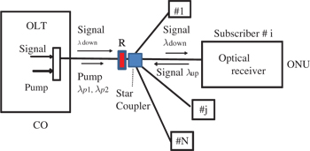
Distributed Raman amplification with a reflector R in PON.
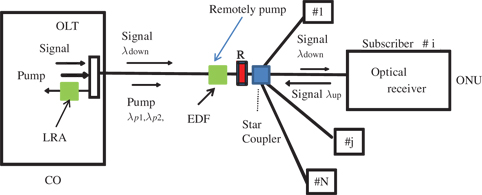
Hybrid Raman amplification in PON.
The configuration shown in Figure 2 is the hybrid Raman amplification. In 10G-EPON, wavelengths of up- and down-stream signals are 1270 nm and 1577 nm, respectively. Two pump waves for DRA, for example 1480 nm pump wave and 1200 nm pump wave, are fed into a transmission fiber from CO for amplification of down- and up-stream signals. To increase the downstream signal amplification gain, an Er-doped fiber (EDF) is inserted before an SC. The 1480 nm pump wave is used for the 1577 nm downstream signal amplification and it is also used for the EDF pumping. As EDFA requires lower pump power when compared with Raman amplification, this can be possible. Both DRA and EDFA can be realized from the pump wave from CO. In the case of long distance transmission, pump power from CO is low because of high loss due to a long fiber length. To realize EDFA, we must seek to the method of remotely pumping. This is shown in Figure 2 as “Remotely Pump.” DRA is realized for upstream signal by pumping from CO. To increase the upstream signal amplification gain, LRA located at CO is used as an optical pre-amplifier.
Secondly, we explain the case of TWDM-PON systems by using the same system configurations, Figures 1 and 2. Eight signal wavelengths for bidirectional transmission will be used in TWDM-PON systems. One pump wave for DRA, for example 1480 nm pump wave, is fed into a transmission fiber from CO for amplifying down- and up-stream eight signals. The reason of one pump wave is clear due to the wavelength allocation shown in Figure 3, which is assumed in this paper. Four wavelengths near 1540 nm are used for upstream and four wavelengths near 1600 nm are used for downstream. We assume 1538, 1540, 1542, 1544 nm and 1596, 1598, 1600, 1602 nm for eight signal wavelengths. In the case of hybrid Raman amplification in TWDM-PON systems, an EDF must be bypassed using optical devices or removed. This is due to the transient property of EDFA against burst upstream signals. Here, we consider the system configuration without an EDF for TWDM-PON, for simplicity.

Assumed wavelength allocation.
In this paper, we treat two types of access networks as a network model. One is NW-model-A, 50 km transmission distance from CO to subscribers and an SC with 64 splitting number. Another is NW-model-B, 10 km transmission distance and an SC with 512 splitting number. The transmission length from an SC to each subscriber is assumed to be zero for simplicity. As for the transmission line loss, we assume the loss is fiber-loss plus 0.3 dB/km. The added 0.3 dB/km value is based on considering many connection points (splice and connector) in access networks.
3 Application of DRA
Here, we show the calculated results of DRA shown in Figure 1 for 10G-EPON and TWDM-PON.
3.1 10G-EPON
In 10G-EPON, wavelengths of up- and down-stream signals are 1270 nm and 1577 nm and their sending power is assumed to be 2 mW (3 dBm). Two pump waves, 1480 nm and 1200 nm, are assumed for DRA. Results, Ps and OSNR, are shown in Figure 4 as a function of pump power for NW-model-A (50 km and 64 splitting number). The same pump power is assumed for two pump waves. That is, 0.4 W in Figure 1 indicates that 0.4 W for 1200 nm and 0.4 W for 1480 nm. The results of Figure 4 show that about 450 mW for 1480 nm and over 900 mW for 1200 nm are required for pump powers in the case of a receiver with −35 dBm receiver sensitivity. More pump power is required for a receiver with −30 dBm sensitivity. Therefore, it is difficult to realize when we consider a fiber fuse phenomenon. Long fiber length and high loss of 1270 nm signal result in transmission difficulty.
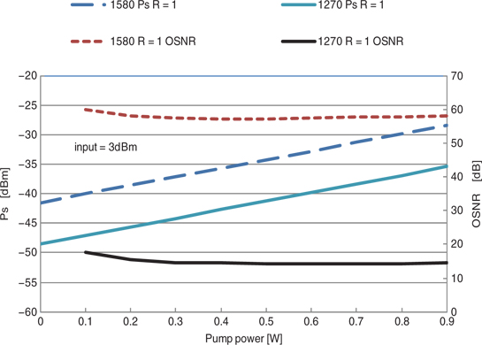
Calculated Ps and OSNR as a function of pump power (application of DRA to 10G-EPON of NW-model-A).
Results for NW-model-B (10 km and 512 splitting number) are shown in Figure 5. They indicate that 0 mW for 1480 nm and 0 mW for 1200 nm are required for pump powers in the case of a receiver with −35 dBm sensitivity. If we can use a −35 dBm sensitivity receiver, DRA is not required. For a −30 dBm sensitivity receiver, 0 mW for 1480 nm and about 120 mW for 1200 nm are required. Contrary to Figure 4, the received signal power difference between 1270 nm and 1580 nm signals is small. This is due to the short transmission distance (10 km) compared to NW-model-A (50 km).
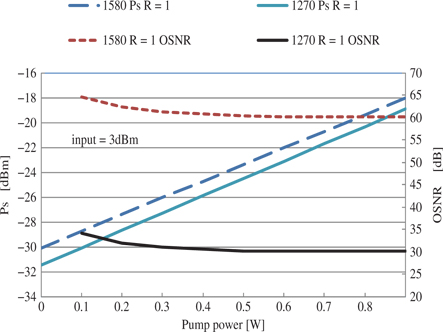
Calculated Ps and OSNR as a function of pump power (application of DRA to 10G-EPON of NW-model-B).
3.2 TWDM-PON
As described earlier, we assume 1538, 1540, 1542, 1544 nm and 1596, 1598, 1600, 1602 nm for eight signal wavelengths in TWDM-PON. One pump wave with 1480 nm is assumed for DRA. Results are shown in Figure 6 as a function of pump power for NW-model-A (50 km and 64 splitting number). As a representative of eight signal waves, only the results for two signal waves, 1540 nm and 1600 nm, are shown in Figure 6. The results indicate that about 500 mW pump power (about 900 mW) is required for a receiver with −35 dBm (−30 dBm) sensitivity.
Similar calculations were made for NW-model-B (10 km and 256 splitting number). Although the results are not shown here, 0 mW pump power (about 50 mW) is required for a receiver with −35 dBm (−30 dBm) sensitivity. Therefore, we can transmit signals without DRA when we use a −35 dBm sensitivity receiver.

Calculated Ps and OSNR as a function of pump power (application of DRA to TWDM-PON of NW-model-A).
4 Application of hybrid Raman amplification
Here, we show the calculated results of hybrid Raman amplification shown in Figure 2 for 10G-EPON and TWDM-PON.
4.1 10G-EPON
DRA and EDFA are used for downstream signal amplification. We assume 0.2 W of 1480 nm pump power for 1580 nm amplification. We also assume the EDF operates as EDFA with gain = 10 dB and NF = 7 dB. With the aid of the previous results of DRA in Figure 4 for NW-model-A, each subscriber receives a signal with Ps = −28.6 dBm and OSNR = 31.4 dB using the hybrid Raman amplification (DRA and EDFA). This indicates the downstream transmission is possible even for a −30 dBm sensitivity receiver.
In the case of upstream, both DRA and LRA are used for amplification. We assume 0.8 W of 1200 nm pump power for 1270 nm DRA. This results in 1 W pump power of DRA of 1580 nm and 1270 nm amplification. For LRA, we assume a high nonlinear fiber (HNLF) with a mode field diameter 2ω = 3.7 μm at λ = 1550 nm and a cut-off wavelength λc = 1.34 μm. This fiber is used for the experiments in Refs [4, 5]. The fiber loss at λ = 1.3 μm is 1.4 dB/km. For calculations, assumed fiber length is 0.5 km or 1 km. Although the results for 3 dBm input signal power are not shown here, about 150 mW LRA pump power (about 300 mW) is required for a receiver with −35 dBm (−30 dBm) sensitivity. On the other hand, the OSNR is about 13.3 dB, which may be acceptable for transmission by using forward error correcting (FEC) technology. To improve the OSNR value, we assume a transmitter with 6 dBm signal power instead of 3 dBm. Results are shown in Figure 7, about 30 mW LRA pump power (about 200 mW) is required for a receiver with −35 dBm (−30 dBm) sensitivity. The OSNR increases to be about 17 dB.
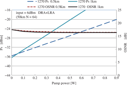
Calculated Ps and OSNR of upstream signals as a function of pump power (application of hybrid Raman amplification to 10G-EPON of NW-model-A).
Results for NW-model-B shown in Section 3.1 indicate that the hybrid Raman amplification is unnecessary.
4.2 TWDM-PON
Results shown in Section 3.2 indicate that only DRA is required for both NW-model-A and NW-model-B and the hybrid Raman amplification is unnecessary.
5 Discussion
Results of DRA and hybrid Raman amplification for both NW-model-A and NW-model-B are summarized in Table 1. The table shows the required pump power in the case of a receiver with −35 dBm sensitivity. If we use a good receiver (−35 dBm sensitivity), Raman amplification is not required in the case of NW-model-B, where the transmission distance is short (10 km) and the splitting number is large (256). On the other hand, Raman amplification is attractive for the case of NW-model-A (50 km and 64 splitting number). Hybrid Raman is required for 10G-EPON because of the high transmission loss of 1270 nm.
Calculated results of DRA and hybrid Raman amplification (a receiver with –35 dBm sensitivity).
| NW-model-A (50 km) | NW-model-B (10 km) | |||
| System | DRA | hybrid Raman | DRA | hybrid Raman |
| 10G-EPON | >900 mW | DRA 200 mW | ||
| Difficult | LRA 150 mW | No need | No need | |
| Possible | ||||
| TWDM-PON | 500 mW | No need | No need | No need |
| Possible | ||||
6 Co-use of LRA
Access network will be upgraded gradually and both 10G-EPON and TWDM-PON systems will be used at the same CO in a transient stage. Co-use of LRA located at CO may be attractive from an economical viewpoint.
6.1 System configuration
We have previously proposed the co-use of LRA [6–8] and the configuration is shown in Figure 8. LRA can amplify the bidirectional plural signals and there are 10 signal waves in the case of the system in Figure 8. We assume two pump waves, 1200 nm and 1480 nm, for LRA. There are two types of co-use of LRA, as shown in Figure 9.

Co-use of LRA in 10G-EPON and TWDM-PON.

Two types of co-use of LRA in 10G-EPON and TWDM-PON.
In the case of (a), both 10G-EPON and TWDM-PON systems share the same transmission line. An EDF must be removed or bypassed using optical devices due to a poor transient property of EDFA in the case of burst upstream signals of TWDM-PON. In (b), 10G-EPON and TWDM-PON systems use separate transmission lines and only LRA at CO is shared. Although an EDFA can be used for 10G-EPON, we consider the system configuration without an EDF for both PON systems, for simplicity.
6.2 Results for both PON systems
We made calculations of Ps and OSNR for the case of NW-model-A (50 km and 64 splitting number). For an LRA fiber, we assume the same type of HNLF as in Section 4.1; however, the longer fiber length is assumed, 1.5 km. The sending power is assumed to be 3 dBm. Calculated results of the signal power Ps and OSNR at each receiver for both (a) and (b) cases are summarized in Table 2. In the case of (a), use of 400 mW pump power of both 1.2 μm and 1.48 μm pump waves for DRA and 350 mW of 1.2 μm and 400 mW of 1.48 μm for LRA is assumed. Ps of up- and down-stream signals are −29.1 dBm (OSNR = 14.5 dB), −29.7 dBm (OSNR = 64.2 dB) for 10G-EPON, and −30.8 dBm (OSNR = 13.0 dB), −30.2 dBm (OSNR = 65.0 dB), for TWDM-PON, respectively.
Calculated results of two types of co-use of LRA.
| Co-use | Pump power | 10G-EPON | TWDM-PON | ||||
| DRA | LRA | Up | Down | Up | Down | ||
| 1270nm | 1577nm | 1540nm | 1600nm | ||||
| a | 400mW (1.2) | 350mW (1.2) | –29.1dBm | –29.7dBm | –30.8dBm | –30.2dBm | |
| 400mW (1.48) | 400mW (1.48) | (14.5dB) | (64.2dB) | (13.0dB) | (65.0dB) | ||
| b | 10G–EPON | 400mW (1.2) | 350mW (1.2) | –29.2dBm | –28.0dBm | ||
| 400mW (1.48) | 400mW (1.48) | (14.5dB) | (66.0dB) | ||||
| TWDM–PON | 400mW (1.48) | –30.7dBm | –30.2dBm | ||||
| (13.0dB) | (65.0dB) | ||||||
In the case of (b), we assume 400 mW pump power of both 1.2 μm and 1.48 μm pump waves for DRA in 10G-EPON and 400 mW pump power of 1.48 for DRA in TWDM-PON. LRA is co-used by two PON systems and it is assumed to be pumped by 1.2 μm wave with 350 mW and 1.48 μm wave with 400 mW. Ps of up- and down-stream signals are −29.2 dBm (OSNR = 14.5 dB), −28.0 dBm (OSNR = 66.0 dB) for 10G-EPON. And those are −30.7 dBm (OSNR = 13.0 dB), −30.2 dBm (OSNR = 65.0 dB), for TWDM-PON.
6.2 Discussion of co-use
Results in Table 2 indicate that it is possible to co-use the LRA by both PON systems. We can construct 10G-EPON and TWDM-PON by using a receiver with around −30 dBm sensitivity when using the pump power shown in Table 2. If we use a receiver with −35 dBm sensitivity, pump powers for DRA and LRA can be lowered.
7 Conclusion
In this paper, we have investigated the distributed and hybrid Raman amplification in 10G-EPON and TWDM-PON systematically. Although there are various types of access networks, we studied two types, A and B, as a model. Using the calculated Ps and OSNR, we consider the case where the distributed and hybrid Raman amplification is necessary or not. Results are summarized in Table 1 and Raman amplification is useful in NW-model-A (50 km and 64 splitting number).
We also studied co-use of LRA at CO by both 10G-EPON and TWDM-PON systems. Co-use may be economical in a transient stage toward the full use of TWDM-PON systems. Results are summarized in Table 2 and we can conclude that a co-use is possible.
References
[1] LuoY, ZhouX, EffenbergerF, YanX, PengG, QianY, MaY.Time-wavelength-division multiplexed optical network (TWDM-PON) for next-generation PON stage2 (NG-PON2). IEEE J Lightwave Technol2013;31:587–93.10.1109/JLT.2012.2215841Search in Google Scholar
[2] GrobeK, EiseltM, PachnickeS, ElbersJ.Access networks based on tunable lasers. IEEE J Lightwave Technol2014;32:2815–23.10.1109/JLT.2014.2312433Search in Google Scholar
[3] KashimaN. Application of Raman amplification using a reflector in passive optical networks. J Opt Commun2012;33:265–72.10.1515/joc-2012-0054Search in Google Scholar
[4] KashimaN. Feasibility study of hybrid-Raman amplifier for passive optical networks. IEICE Commun Express2013;2:118–22.10.1587/comex.2.118Search in Google Scholar
[5] KashimaN. Upgrade of passive optical network using Raman amplification. J Opt Commun2013;34:315–23.10.1515/joc-2013-0039Search in Google Scholar
[6] KashimaN. Bidirectional lump Raman amplification for both 10g-EPON and TWDM-PON. IEICE Commun Express2014;3:39–43.10.1587/comex.3.39Search in Google Scholar
[7] KashimaN. Fiber design consideration for lump Raman amplification in passive optical networks. IEICE Commun Express2013;2:496–500.10.1587/comex.2.496Search in Google Scholar
[8] KashimaN. Properties of bidirectional lump Raman amplification for co-use of 10g-EPON and TWDM-PON systems. J Opt Commun2014;35:339–45.10.1515/joc-2014-0017Search in Google Scholar
©2016 by De Gruyter
Articles in the same Issue
- Frontmatter
- Systematic Studies of Distributed and Hybrid Raman Amplification in 10G-EPON and TWDM-PON
- Raman Amplifier Performance under New Wavelength Ranges
- Linewidth Enhancement Factor and Amplification of Angle-Modulated Optical Signals in Injection-Locked Quantum Cascade Lasers
- QKD-Based Secured Burst Integrity Design for Optical Burst Switched Networks
- Quality of Recovery Evaluation of the Protection Schemes for Fiber-Wireless Access Networks
- Demand Routing with ASE Impairment Consideration in Long Distance Optical Networks
- Performance Analysis of DPSK-OCDMA System for Optical Access Network
- One bit/s/Hz Spectrally Efficient Transmission for an Eight-Channel NRZ-Modulated DWDM System
- Power Analysis of Soliton Pulse for ROF-OFDM System
- Simulative analysis of different modulation formats for RoF Transmission System
- Simulative Analysis of Multi-tone RoF Transmission System
- Numerical Analysis of Dispersion Compensation Schemes for Pseudo-linear Transmission System
- Performance Analysis of SAC Optical PPM-CDMA System-Based Interference Rejection Technique
- Analysis of Performance for 100 Gbit/s Dual-Polarization QPSK Modulation Format System
- News
- News

