On the design of unconventional testing machines for engineering testing – the case study of advanced joining processes unit
-
António Francisco G. Tenreiro

 ,
Ricardo J. C. Carbas
,
Eduardo A. S. Marques
,
Carlos M. da Silva
,
Ricardo J. C. Carbas
,
Eduardo A. S. Marques
,
Carlos M. da Silva

Abstract
Structural adhesive joining has become a widely used joining method for various types of structures, thus avoiding more conventional joining methods. In this manner, adhesive materials may be present in structures which suffer loading conditions that may not be normally considered in the design phase, such as high-strain rate conditions or creep and torsional loading. In these situations, adhesive properties and mechanical behaviour are sometimes not well understood, thus requiring special machine testing setups that can only be built for the specific application. Therefore, this paper provides a brief overview of proposed machine architectures for a torsion testing apparatus, a tensile & compressive Split Hopkinson Pressure Bar (SHPB), a drop-weight apparatus and a three station creep testing machine with a climactic chamber. Each testing apparatus has been designed by graduate students during their master thesis projects, and facilitated in the production of interesting and relevant scientific output in the field of structural adhesive behaviour.
1 Introduction
In the book entitled Academic Strategy: the Management Revolution in American Higher Education, George Keller states, among other things, that strategic planning [of a research and/or higher learning institution] looks outward and is focused on keeping the institution in step with the changing environment [1]. In this manner, academic and research institutions must remain attentive to the trends observed in other international institutions, as well as in industrial and commercial sectors [2].
One such field, which has gained the attention of both the industry and the research community, is adhesive joining. Adhesive joining has various mechanical advantages over other conventional joining methods, namely the ability to join dissimilar materials without requiring hole drilling, as it is the case with riveting or with bolting. In this manner, the stress distribution is also comparatively more uniform than with mechanical joining or welding [3]. These are just some of the reasons why adhesive joining has been adopted in vehicular structures [4], [5], [6].
However, the complexity that adhesively bonded structures acquire [4], the eventual degradation of mechanical properties due to environmental or loading conditions [7], [8], [9], and the influence of damage [10], [11] involve the need to characterize and test adhesive materials and bonded joint specimina. Succinctly, experimental testing is always required. This has been the area of domain of various research entities, both academic and industrial. One such example is the Advanced Joining Processes Unit (AJPU) of the Institute of Science and Innovation in Mechanical and Industrial Engineering (INEGI), and of the Faculty of Engineering of the University of Porto (FEUP).
Given this need to experimentally test adhesive materials and bonded joint specimina, testing machines and aparatuses are required. A simple solution would be to acquire testing machine setups. However, this may not always be possible since (a) machine acquisition may entail high acquisition and/or maintenance costs, (b) commercially available machines may not fulfill all machine requirements. Therefore, research projects will sometimes entail machine design [12], [13].
The design of an experimental testing apparatus follows a specific workflow, which is represented in Figure 1, and is based on reference [14]. In essence, the project of a machine starts by the analysis of the requirements, followed by the definition of the architecture of the machine and its various subsystems. With this, the mechanical design of the testing apparatus, and its subsystems, begins, and involves component design and assembly (into subsystems and into the machine as a whole) with the help of a Computer Aided Design (CAD) and/or Computer Aided Engineering (CAE) software. However, this stage may also involve the initial use of numerical tools to perform functional simulations with, for instance, MathWork Simulinks®, in order to mathematically validate the intended dynamic behaviour of the subsystem [15]. Component development in CAD software will also involve design topics, such as material selection, dimensional and geometrical tolerances, or surface finish. With the CAD project finalized, components are manufactured. While these operations occur, actuators, sensors and transducers are acquired and incorporated in the machine, while it is being assembled. During the mechanical assembly stage, an electrical power and logic circuit is implemented to guarantee command and actuation of the testing apparatus, while also acquiring the measured physical phenomena occurring during the test. These signals are sent to a Data Acquisition (DAQ) board, which is connected to a computer. To achieve this, a software must be programmed, that can command the apparatus, and that can acquire and process the measured signals. Finally, a validation of the machine is required.
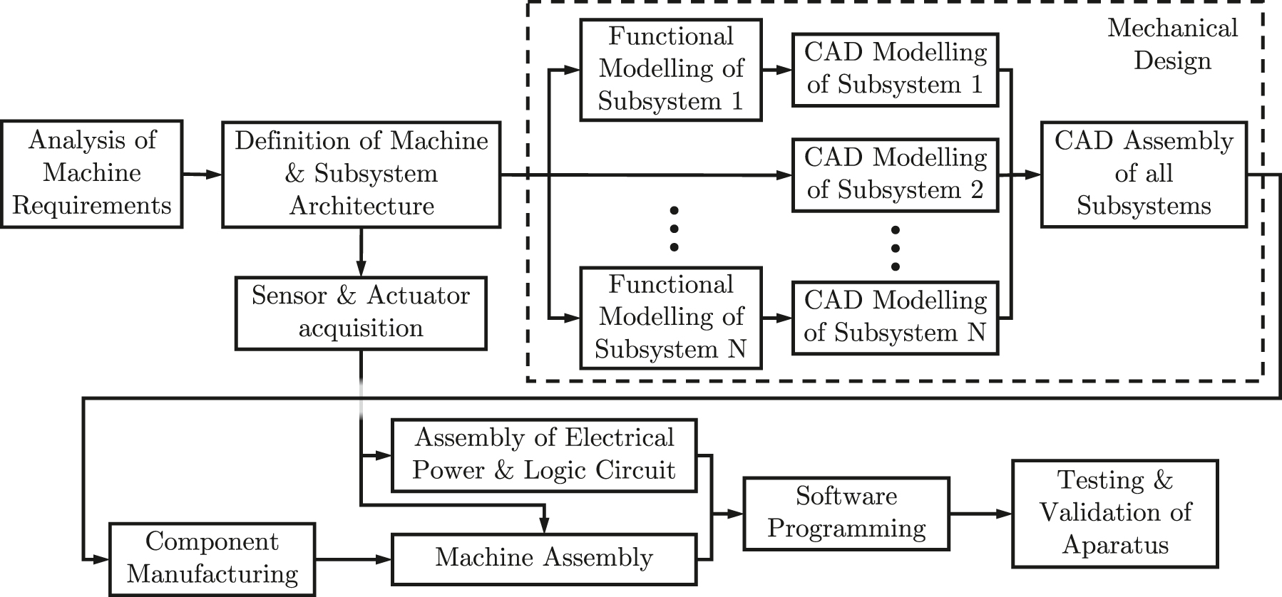
Generic scheme of machine project workflow.
Note that the workflow schematized in Figure 1 is a simplification, since several tasks may require some iterations before achieving a final architecture or design of the machine.
Machine design is a critical discipline in mechanical engineering education. It requires students to master a wide range of skills, including structural calculation, control system design, manufacturing processes, and technical drawing. However, it is natural that students who graduate with a mechanical engineering degree are not yet fully prepared to undertake machine design in a professional setting. This is because the skills required for machine design are complex and require a great deal of experience. One way to mitigate this problem is to expose students to more challenging machine design tasks. An academic setting, where cutting-edge research with highly specialized equipment takes place, provides the perfect environment for this [16].
At the AJPU, students who wish to pursue a career in machine design are integrated into master’s thesis programs that target the custom design of testing equipment. This equipment is necessary to drive the research on advanced joining processes that is constantly carried out in this group. By participating in these programs, students are tasked with creating concepts, designing components and control systems, and then assembling, testing, and validating the equipment they have designed. They are always supported by teachers who are knowledgeable in these subjects. The complexity of this process helps students to become more confident in their skills and to identify areas for improvement. As a result, they leave the academic setting better prepared to face the challenges of professional environments. In addition, academic research units also benefit greatly from this process. The constant development of novel testing equipment drives innovation and helps to advance the field of mechanical engineering [2].
In this manner, this paper presents examples of testing machines which were designed, manufactured, assembled and validated by AJPU, namely a torsion testing machine, a Drop-weight testing machine, a tensile and compression Split Hopkinson Pressure Bar (SHPB) and a creep testing machine. Furthermore, examples of scientific output provided by the use of these machines is outlined.
This paper is structured as follows. Section 1 presents an introduction on the design of unconventional testing setups. Sections 2–5 present the proposed architecture for a torsion testing machine, a tensile and compressive SHPB testing setup, a Drop-weight apparatus, and a creep testing machine respectively. These sections also showcase their relevance in the scientific field of material testing and machine design, given the scientific output these machines enabled. Finally, Section 6 finalizes with some concluding remarks.
2 Torsion testing machine
While conventional tensile and compression test allows one to determine the elastic properties of adhesive materials with bulk specimina, these experiments are unable to accurately characterize the behaviour of adhesives in the plastic domain [17]. Against the backdrop of uniaxial testing, various methods to test the performance of adhesives under shear conditions have emerged, such as Single Lap Joint (SLJ) testing [18], Arcan testing [19] or Thick Adherend Shear Test (TAST) [20].
While these bonded joint specimen geometries allow for testing in shear conditions, butt joint geometries, such as solid butt joints or Napkin-Ring specimina, provide better experimental results. This is the case since these type of joints are under torsion loading, which means that all of the bondline area is being loaded and contributing to the shear resistance [21], [22]. Therefore, a torsion testing machine enables the accurate characterization of adhesives and adhesive joints under pure shear loads.
2.1 Torsion machine architectures
It is noted that various commercial torsion testing machines exist in the market, which are widely used in scientific research to test commonly used materials in engineering scenarios, such as metal alloys, polymers and composites [23], [24]. However, these machines cannot test all materials, and case studies have been found where specially designed apparatuses were used to test welded specimens [25] and shape memory alloy tube specimens [26], to name a few.
2.1.1 Commercial & unconventional torsion testing setups
Various commercial torsion testing machines exist that can test commonly used engineering materials. For instance, ZwickRoell GmbH & Co. KG have a range of horizontal torsion testing machines, where a servo-controlled electrical motor control can apply a torque loading of up to 500 Nm. Their testing machines also allow for the generation of a second axial load of up to 500 N [27]. Instron® also provides a similar torsion apparatus series, named MT MicroTorsion Series, which can test specimens with a maximum torque capacity varying between 22.5 Nm and 5650 Nm. In their testing machines, one of the grips is fixed, while the other moves on a dual linear slide, thus offering high torsional stiffness, and a strain gauge torque cell is used to measure the torque being exerted [28].
These are just some examples of commercially available testing machines. In general, commercially available machines can deliver torque at different ranges, rarely going above approximately 5000 Nm. According to the literature, torsional testing of polymers may attain torques of up to 250 Nm, while metal specimens can attain much higher torque values. For the specific case of adhesive torsion testing, maximum torque values tend to be lower than 100 Nm for stiff adhesives, while the characterization of flexible adhesives requires much lower values [21].
Typical torsion testing machines need to have a relatively high axial stiffness [21], [27], [28], but precise alignment of the specimen may not be guaranteed, especially when the specimen has a complex mechanical behaviour, such as shape memory metal alloys or certain types of adhesives [21], [29]. Alternatively, special torsion fatigue testing devices have also been manufactured [30], [31]. In this manner, unconventional testing machines may be required.
Avila Ambriz et al. [30] developed a fatigue torsion machine where a servo-motor rotates one of the chucks fixing the specimen. This rotation is not directly transmitted to the specimen, but is transmitted with the help of a chain and a spocket. The developed setup also allows for bending loading with the help of a second linear actuator. Bustos and Vargas [31] have proposed a torsion fatigue testing machine that makes use of a flywheel. In this manner, one of the fixing chucks is connected to either a steel or an aluminium alloy flywheel, while the other is moved by an AC asynchronous motor that is commanded with the help of a variable-frequency drive. The electric motor is mechanically coupled to a flexible V-belt transmission and a two-stage gear reducer. Coupled to this gear reducer is a four bar linkage, with a geared rocker and crank that converts a continuous circular motion into an alternating semi-circular motion.
Regarding the development of special torsion apparatuses for adhesive joint testing, very few setups have be proposed. Brinz, Lewis and Geiger [29] patented an apparatus that can test adhesive joints under a combined tensile-torsion-shear load, which avoids unwanted displacement of the bonding surface. Goanţă et al. [32] proposed the use of a cam device to test specimens under a combined tension-torsion fatigue cycle. In this manner, the proposed device can be easily implemented in common uniaxial testing machines.
2.1.2 Proposed torsion testing architecture
The testing apparatus designed and manufactured by the AJPU research unit, which has a different machine architecture, is presented in Figure 2. This machine should be able to test bulk specimina, as well as butt joints and tubular joints with diameters varying between 5 and 30 mm, and lengths between 50 and 150 mm. The rotational test speed can vary between 0.05 and 1 rpm (which is equivalent to 5 ⋅ 10−3 and to 0.105 rad s−1). The maximum torque required is of 60 Nm, while the resolution of the angular transducer is of 0.0005°. For the final machine project requisite, spurious tensile stresses must be below 1 MPa. These project requirements are of importance in defining the kinematic chain of the testing setup, since the structural kinematic chain must be stiffer than the specimen being tested. In this manner, the machine modes of vibration will not influence the control of the machine.

Scheme of the developed torsion testing machine setup, with detailed views.
One must note that commercially available machines and most torsion testing apparatuses dispose their kinematics chain in a horizontal axis. However, with this strategy, the machine does not self adjust its grips in case of any misalignment, present in either the specimen, or in the assembled machine components. As such, normal torsion machines and specimens require tight dimensional and geometrical tolerances. Furthermore, the horizontal positioning of a long specimen will lead to an unwanted bending. The proposed architecture has a testing axis in a vertical direction, thus avoiding these issues [21].
In this manner, the torsion is imposed by the rotation of the NX 310EAPR7301 servomotor, which has a peak toque of 6.6 Nm and an angular speed of 2300 rpm at 230 V. This servomotor is coupled to a three stage planetary gear train, with a reduction ratio of 216:1, yielding a maximum torque of 80 Nm. The output shaft of the gear reducer is connected to the lower shaft (which is connected to the lower chuck holding the specimen) with the help of a torsionally rigid coupling. This coupling allows for axial, radial and angular misalignments, which is possible thanks to two duplex stainless steel diaphragms. Furthermore, to compensate for these misalignemets, both upper and lower shafts can have a deviation of up to 4°, relative to the vertical axis, thanks to two ball bearings, one for each shaft, as represented in Figure 3. Note that the machine’s mass center is placed above the ball bearing, with a huge contribution by both the lower shaft and the lower grip. In this manner, the normal functioning of the machine is unstable. To avoid structural dynamic issues, a counterweight is placed below the ball bearing.
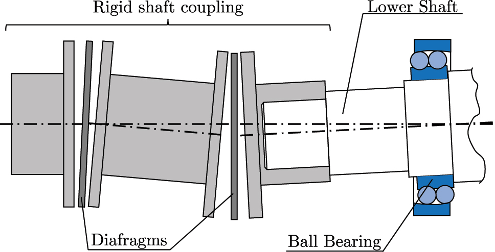
Schematic representation of misalignement compensation with both the shaft coupling and the ball bearing.
The upper shaft, which is fixed to the upper chuck, as shown in Figure 2, is connected to a torsionally rigid coupling. This coupling is also connected to the torque transducer, with a sensitivity of 1.0 mV/V and the capability of measuring torque of up to 100 Nm, which is above the required 60 Nm [21].
The torsion testing apparatus has four different testing modes: testing with controlled angular velocity, creep testing, stress-relaxation testing and testing with controlled torque. Each testing mode required its own controller for the servomotor [33]. The acquisition of the angular displacement is achieved with the help of a microscopic video camera.
2.2 Scientific output
As stated before, torsion testing machines are an important tool for experimentally testing adhesive joints, because they can provide a more accurate and complete assessment of the joint’s strength and performance. Torsional loads generate a more uniform stress distribution in the adhesive layer, which can help to identify any weak spots or potential failure modes. In addition, torsion testing machines can be used to measure with precision the shear strength of the adhesive, which is a critical property for determining the joint’s load-carrying capacity. Shear strength is the force required to break the adhesive layer, and it is typically measured in terms of the shear stress at failure. The development of this testing machine has initially resulted in the preparation of a scientific paper on this subject, mostly related to design of the innovative vertical machine, its configuration, control system and validation process [21]. The machine has enabled to carry out complex consulting projects with industrial partners, mostly related to the subject of tubular joints for electronics cooling applications. These types of joints are usually subjected to complex torsional loads under cyclic conditions, which were able to be successfully reproduced using this type of equipment [34]. Furthermore, a significant component of this work was also devoted to the study of the optimal adhesive thickness under torsional loads, allowing to determine that there is a significant effect of the adhesive layer thickness on the shear strength and stiffness of the adhesive in tubular joints [35]. Lastly, this equipment also played a key contribution to the development of numerical models able to reproduce the mechanical behaviour of tubular joints, providing experimental data which allowed to validate the model performance [36].
3 Tensile & compressive split Hopkinson pressure bar
Normally, material characterization is commonly done in quasi-static conditions, where specimina are tested under small strain-rate conditions, i.e.,
![Figure 4:
Scheme of a conventional compressive SHPB testing apparatus [38], [39].](/document/doi/10.1515/jmdai-2023-0002/asset/graphic/j_jmdai-2023-0002_fig_004.jpg)
This subsection will discuss the project of a tensile and compressive SHPB apparatus. For simplicity’s sake, the functioning of a compressive SHPB is presented, and the difference between compressive and tensile apparatuses is discussed. Afterwards, a description of the architecture of the tensile and compressive SHPB apparatus, proposed by the AJPU research unit, is presented, with focus on the actuator and its associated braking system, and the gripping system for tensile testing.
3.1 SHPB apparatus architecture
3.1.1 Conventional tensile & compressive SHPB setups
A typical SHPB setup is composed by an actuation sub-system, the bar setup, and a data acquisition system. The most commonly adopted actuation method consists in launching a Striker Bar from a pressurized gas gun, which will hit the free extremity of the incident bar (also known as an input bar). From this impact, a compressive stress wave is generated, and moves towards the specimen, which is fixed between the incident bar and the transmission bar (or output bar). In the interface between the input bar and the specimen, part of the incident wave is reflected backwards, while the other part is transmitted to the specimen and, afterwards, the transmission bar. Finally, the transmitted stress pulse is absorbed by the momentum trap in the opposite side of the bar setup.
While this occurs, strain gauges connected to Wheatstone bridges, which are placed in the middle of the input and output bars, measure the three stress pulses and send the measurements to a high sampling frequency oscilloscope, or a computer with a DAQ board. Other auxiliary transducers may be present, depending on the characteristics of the SHPB machine in question, such as transducers to register the striker velocity before impact [38], [40].
Initial tensile SHPB setups did not follow a conventional architecture, unlike compressive SHPB machines, and various strategies were followed, such as the ones presented here. For a more detailed description of various tensile SHPB machines, please consult reference [38]. Lindholm and Yeakley [41] designed a top-hat specimen, which was positioned between a solid input bar and a tubular output bar. In this manner, an incident compressive pulse is generated, identically to that of compressive testing apparatus, but this wave is converted to a tensile wave while passing through the specimen. Nicholas [42] also proposed the use of a conventional SHPB compressive machine, where the specimen is fixed with threads, and a cylindrical collar is placed on top of the specimen. In this manner, the compressive stress pulse passes through both the collar and the specimen without hindering the integrity of specimen, until reaching the free end of the output bar, where it is reflected as a tensile wave. Afterwards, this tensile wave travels in the opposite direction, and is exclusively transmitted to the specimen. Harding and Welsh [43] proposed an alternative SHPB bar setup, where a transmission bar was placed inside a compressively loaded hollow input bar, and the test specimen was fixed with the help of a Yoke. Hauser [44] proposed a similar architecture where both the input and output bars are placed inside a hollow weightbar.
Despite the various solutions for tensile high strain-rate testing, the architecture defined by Nemat-Nasser et al. [45] has gained significant attention and is increasingly being adopted [46], [47], [48]. The proposed architectural solution consists in launching a Striker Tube, placed on the incident bar, towards an impact flange, which is placed in the free-end of the incident bar. The impact between both elements will generate a tensile wave that will propagate towards the specimen. The proposed SHPB testing machine architecture is based on this constructive solution.
3.1.2 Proposed SHPB architecture
As previously mentioned, there is a wide variety of SHPB architecture setups for high strain-rate tensile testing, which may not always be compatible with SHPB compressive setups. In this manner, a machine architecture is proposed, where one can perform tensile or compressive high strain-rate testing with a reduced number of assembly alterations. In this manner, the architecture schematized in Figure 5 is proposed. Both loading setups can be divided into three main subsystems – a pneumatic actuator, a pressure bar setup, and a braking system designed specifically to stop the actuator.

Simplified schematic representation of the proposed SHPB setup. (a) Compressive testing setup. (b) Tensile testing setup (only the pressure bar subsystem is presented).
The pressure bar setup for the compressive apparatus follows the same architecture as the one represented in Figure 4, given that it is widely used in this type of machines. For tensile testing, the pressure bar subsystem is similar to the ones proposed by Nemat-Nasser et al. [45] and by Gerlach et al. [46]. To generate the high strain-rate loading, the striker bar needs to impact the Input Bar at high velocities. Impactor velocities for SHPB testing are typically of 20–30 m s−1 [38]. However, velocities can reach up to 50 m s−1 [37].
To attain these velocities, a novel symmetric double-rod pneumatic actuator was designed, that can attain high velocities in a relatively short stroke. An initial functional simulation of the system reveals that, for a compressed air supply pressure of 8 bar, a maximum velocity of 23 m s−1 is attained [39]. However, conventional pneumatic actuators can only reach much lower velocities and, therefore, a specially designed braking system is required to stop the actuator. This is done with the use of a transmission lever that is hit by a stopping car coupled to the actuator’s rod. This transmission lever is also connected to a set of disc springs (also referred to as Belleville springs) and two shock absorbers [49].
It is noted that, in the beginning of a compression test, the Striker Bar is inside of a striker holder, fixed to the rod of the actuator, and, when the rod of the pneumatic cylinder begins to decelerate, the Striker Bar leaves the Striker Holder, and is freely launched towards the Incident Bar. Likewise, for the tensile test, the Striker Tube is launched inside a striker holder, and attains a free motion inside the tensile striker holder, while the rod is being decelerated by the braking system. Afterwards, the Striker Tube hits a Flange attached to a Loading Bar, similarly to what was proposed by Nemat-Nasser et al. [45], thus generating a tensile pulse. During these motions, optical sensors indirectly register the velocity of the impactor during its free motion, and strain gauges register the pulse wave through the Incident and Transmission Bars.
3.2 Scientific output
Multiple factors can affect the mechanical behaviour of bonded joints at very high strain-rates, including the properties of the adhesive, the adherends, and the geometry of the joint, making it extremely important to consider all of these factors when designing and testing bonded joints for high strain rate applications [50]. However, significant challenges arise when attempting to do so, such as the difficulty to create and control high strain rates in laboratory experiments and the fact that the behaviour of bonded joints can be sensitive to small variations in the material properties or the geometry of the joint (which can lead to major changes in the local strain rates). As a result, there is a limited amount of experimental data available on the mechanical behaviour of bonded joints at very high strain rates. The design of this equipment [49], [51] allows one to open the door to novel testing and characterization procedures, specifically designed to operate with bonded joints. Some of this development work has already been undertaken at the AJPU, mostly targeting the definition of cohesive zone laws suitable for modelling the material behaviour at very large strain rate. One such work, developed by Nunes et al. [52] has focused on novel and simplified method to experimentally obtain traction-separation laws, estimating the fracture energy both for mode I and II under impact conditions. This was achieved by resorting to an SHPB equipment with especially designed specimens. The use of a direct method, as shown by Simões et al. [53] allows for direct and accurate modeling with cohesive elements in finite element modeling approaches.
It must be noted that the beforementioned tensile and compressive SHPB apparatus is still in the component manufacturing and machine assembly stage (see Figure 5). However, given the complexity of the machine project at hand, several papers [39], [49], [51] have been published regarding the design of several subsystems.
3.2.1 Complex pneumatic high-speed actuator
Tenreiro et al. [39] performed an initial requisite study for the SHPB apparatus, and determined that velocities of up to 25 m s−1 may be required for adhesives and adhesive joint testing. Furthermore, tensile and compressive stress wave generation was required. In this manner, a symmetric double-rod pneumatic cylinder, that can move horizontally with high acceleration and with reduced friction, is considered as the best actuator solution for this apparatus. To achieve this, the actuator subsystem requires:
No physical contact between the rod and piston of the actuator, and its static components. This means that no piston seals, rod seals or guiding elements are present in the assembly, and that the rods are supported by a contactless method, such as air bushings (which are the blue rectangles in Figure 5a). Note that without the seals, there will be air leakages;
A reservoir, to maintain a high air mass flow without fluctuations, thus guaranteeing a continuous acceleration movement;
The maximum air flow be to used at the start the acceleration movement, during the first instances of movement. This requirement is essential, since, as previously stated, no seals are present in the actuator, and air leakages will inevitably exist.
![Figure 6:
Detailed view of the actuator and corresponding braking system [39], [49].](/document/doi/10.1515/jmdai-2023-0002/asset/graphic/j_jmdai-2023-0002_fig_006.jpg)
Given the complexity of the architecture, a functional model of the actuator dynamics is required. A thorough description of the dynamic mathematical models to estimate the behaviour of the high-speed actuator is outside the scope of this work. However, one must point out that this required the modeling of the air reservoir, directional and quick exhaust valves [54], both pneumatic chambers [55], [56], the leakages between each chamber and the atmosphere, as well as air leakages between both chambers [57], and the actuator mechanics. For more information, please consult reference [39].
Given the required high velocities needed, there is a need to brake the actuator in a relatively short portion of the actuator’s stroke, which corresponds to 0.3 m of the total stroke of 1.8 m. In light of this, and given that the initial air pressure before movement will define the velocity of the striking element of the SHPB, an actuator braking system is required. This subsystem is composed by:
A Transmission Lever, whose rotation axle is placed such that a reduction of velocity is achieved;
A Belleville spring set, that can withstand the high generated loads in the deceleration stage, with minimal displacement, and that will absorb part of the velocity;
A set of Shock Absorbers, that dissipate energy for linear velocities of up to 5 m s−1 [58].
3.2.2 Gripping system for tensile testing
An important aspect of tensile SHPB testing is the method in which the specimen is fixed. In compression testing, the specimen is simply placed between both bars with a slight tightening. In fact, to avoid overestimation of the specimen’s strength, caused by the interfacial friction of this tightening [59], lubricant and grease may be used [60], [61]. However, for tensile testing, this is simply impossible to perform, since, when the tensile wave passes up to the specimen, the Input Bar will inevitably suffer a displacement fromward the specimen, which will then fall. As such, the specimen needs to be clamped, glued or threaded to both Incident and Transmission Bars [62], [63], [64].
Based on the work of Ledford et al. [63] and of Constantino [65], Bernardo et al. [51] designed a gripping system, where an SLJ specimen is fixed on both ends with a grip, which will be threaded onto both the Input and Output Bars. Each grip consists of two components, one of which will be screwed on top of the main grip component, that has a cavity specially designed for specimen fixture. A necessary step of this work was the optimization of the thread shape, with three posssible shapes being studied: a quandrangular thread shape, a typical triangular ISO-thread shape, and a trapezoidal thread shape. This last thread profile was chosen, with a nominal diameter of 14 mm and a pitch size of 2 mm, which are present in international standards on trapezoidal threads [66].
4 Drop-weight testing machine
As previously stated, the strain-rates attained in quasi-static testing are considerably low, below 1 ⋅ 101 s−1. Conversely, an SHPB testing apparatus can load specimina at relatively high strain rates, i.e.,
4.1 Drop-weight setup architecture
Much like with torsion testing machines, some Drop-weight testing apparatuses are available in the market. However, these testing devices are designed to test typical specimen geometries, such as dog-bone specimina, or cylindrical bulk specimina. Moreover, as previously stated, adhesive testing usually requires the use of more complex specimen geometries. One such case is the SLJ specimen [68], whose mechanical behaviour resembles that of real-application adhesively bonded structures [69]. It is also the case where one might wish to study the behaviour of real-application adhesively bonded components, for a more accurate understanding of the mechanical behaviour at these strain-rates [70].
4.1.1 Alternative drop-weight apparatus architectures
Normal Drop-weight impact machines follow a typical behaviour where an impactor, normally referred to as drop mass, is initially positioned at a certain height, from which it is released. The test specimen, which is placed below, is hit by the drop mass, and thus, the energy being transferred to the specimen’s deformation originates from the kinetic energy of the drop mass, which is a function of the mass, m d , and of the initial height, h 0 [71].
Ideally, this type of testing machines should have a anti-rebound mechanism or energy absorption device, to guarantee that no rebound of the drop mass occurs, and that no subsequent impact on the specimen occurs. However, not all drop tower machines have such a mechanism [72], [73]. One such testing apparatus with this shortcoming is the commercially available ZwickRoell Amsler MIT230F drop tower model, which can launch a drop mass of 23.5 kg from a height varying between 110 and 1000 mm, attaining a maximum velocity of 4.4 m s−1. However, this apparatus does not have a setup avoiding drop mass rebounds [74].
Ambur et al. [75] proposed an apparatus where a drop mass assembly, that is initially lifted with the help of an electrical motor and a halyard, is released from an inputed height, until hitting a specimen. A damping unit consisting of a dashpot and a helical spring (a shock absorber), which is present inside the Drop-weight, functions as a anti-rebound system, thus avoiding subsequent unwanted impacts. Zhang et al. [76] developed a drop-tower machine to test concrete specimina. In this manner, this machine has a height range of up to 2595 mm, and two possible drop masses: an aluminium one, whose mass is of 18.60 kg, and a steel impactor, with a mass varying between 60.55 kg and 315.55 kg. Accelerometers are placed on the specimen, while a piezoelectric force transducer, which can measure loads of up to 177.92 kN, is present inside the drop mass. A magnetic strip is laced in one of the columns to determine the height of the drop mass. Adachi et al. [77] developed a small Drop-weight apparatus, where a thin aluminium drop mass, which has a magnet inside, is dropped from a tubular glass and hits the specimen being tested. The magnet passes through two coils, thus generating an electromotive force in each coil, given that these coils are placed at specific heights, the signals being measured allow the estimation of the velocity of the drop mass.
4.1.2 Proposed drop-weight apparatus
The proposed drop tower, which is schematically drawn in Figure 7, was projected and built by the AJPU research unit with several project requirements in mind. Firstly, this apparatus should be able to release a drop mass of 56 kg from heights of up to 1.27 m, reaching an impact velocity of 5 m s−1, which yields a maximum energy of 700 J. For the maximum working velocity, a minimum impact energy of 50 J is also required, which translates to a weight impactor with a mass of 5 kg. Finally, the drop mass can be positioned at a specific inputted height with a resolution of 1 mm.

Scheme of the developed drop tower setup.
In this manner, a gearmotor is used to rotate a bronze barrel with helicoidal profile, where the steel cable will be coiled during the ascending movement of the drop mass. It is noted that this gearmotor has a gearbox coupled to it, which performs a reduction of 1:80. To guarantee that the steel cable remains in a vertical position, an Axial Connector moves the barrel throughout the shaft in which is it mounted on. To help this, a second shaft, with a bronze screw, is also mounted in the Lifting System, and rotates accordingly with the help of a gearbox, thus enabling the winding of the steel cable. A three-dimensional rendition of this subsystem is presented in Figure 7. The electric motor, which has an encoder included, is controlled with the help of a PID controller [33].
The carriage connects the drop mass with the steel cable, thus allowing the drop mass to released from a specified height. This carriage has a release clamp where an upward shaft of the drop mass is fixed onto a sleeve-ball carrier and a compressed spring. Afterwards, the drop mass is released with the help of a pneumatic cylinder. A detailed view of this mechanism is shown in Figure 7.
While the drop mass falls, a fork attached to the impactor will pass through an optical detector, to determine the velocity of the drop mass. In this manner, the first tine of the fork will trigger a counter, while the second (and last) will stop said counter, thus allowing one to measure the velocity of the impactor right before the impact. However, before the test starts, a subroutine is triggered, where the positioning of the optical detector is made, by first zeroing its position (hence the micro-switches).
A Rebound Capture System was also implemented in this apparatus, with the aim of preventing subsequent rebound, after the first impact. As such, a system based on a simple lever mechanism was proposed. Initially, an arm, placed on each side of the drop mass, is in a horizontal position, and a fast-acting pneumatic actuator (one per arm) is actuated by a directional valve, forcing the rotation of the arm, thus lifting the drop mass. Shock-absorbers are also present to absorb the energy caused by the impact. This system is presented in Figure 8a. Before the mechanical design of this system, a functional simulation was developed, where several dynamic phenomena were included, such as the directional valve supplying the actuator [54], the active pneumatic chamber of the actuator [55], [56], the arm mechanics, and a LuGre Friction Model modeling the friction between the piston and the body of the pneumatic cylinder [78], [79], [80].

Constructive details of AJPU’s drop-weight testing machine. (a) Rebound capture system. (b) Velocity acquisition system.
While the impact occurs, a piezoelectric load transducer, placed inside the drop mass, acquires the load being generated during the impact. An accelerometer is also present inside the drop mass, thus acquiring the acceleration during the fall and during the impact [81].
4.2 Scientific output
Drop-weight testing machines are a valuable tool for evaluating the impact resistance of bonded joints in a quick and simple manner. This is important because the impact resistance of a bonded joint can be affected by a number of factors, including the joint geometry, adherend and adhesive properties and environmental conditions. By using drop-weight testing machines, it becomes possible to validate joint designs under impact conditions that they are likely to encounter in real-world applications, especially in impact sensitive applications, such as those found in the automotive industry [3]. Following the development of the aforementioned drop-weight impact testing machine, multiple research works have been carried out in the AJPU. One such example is the development and assessment of the impact performance of functionally graded adhesive joints, a novel joint configuration that gradually varies the adhesive properties along the overlap to minimize stresses [82]. The work of Rosendo et al. [83] has focused on a more practical application in the automotive industry, seeking to assess the interaction between the loading rate, temperature and moisture in the performance of joints with configurations typical of the automotive sector. This work was later expanded to assess the performance of more modern and highly ductile polyurethane adhesives [84]. In parallel, characterization work has also been carried out under mixed mode conditions, subjecting fracture mechanics specimens to shear and tensile loads [85]. Other important research works have used this equipment to model the performance of very large and complex vehicle structure, such as the bonded frame-header of a vehicle body [70].
5 Creep testing machine
The adoption of polymeric adhesives in industrial and structural applications has become widespread, as mentioned in the introductory section. However, adhesive materials are mostly characterized in quasi-static condition, where bulk tensile and SLJ tests are performed. However, these materials have a viscoelastic behaviour, and, consequently, perform differently when under a long term load [86], [87]. In this manner, adhesive materials must also be characterized in long term loading scenarios, where various factors are important, such as the load level and period, the type of adhesive and of the substrate, ambient conditions (temperature, relative humidity), etc. [88], [89], [90].
5.1 Creep setup architecture
It is common to perform creep testing of adhesive bulk and joint specimina in either commercially available universal testing machines [89], [91], [92], [93], or in small lever or weight apparatuses [88], [92], [94]. However, more complex setups may also be required. To the best of the authors knowledge, no testing apparatus was designed with the specific goal of testing adhesive and adhesive joints under specific creep conditions. As such, this section aims to present the specially designed testing apparatus to experimentally test adhesive bulk and adhesive joint specimina under creep conditions.
5.1.1 Proposed creep testing apparatus architectures
The proposed creep testing machine contains three testing stations, as shown in Figure 9, each one with two wedge action grips. The load capacity should be of 2.5 kN, with a maximum grip displacement of 300 mm. As mentioned in the beginning of the section, temperature conditions influence the creep behaviour of adhesive materials, and, therefore, a climactic chamber is also required so that tests can be performed at a temperature range between −100 °C and 200 °C.

CAD rendition of the multi-station creep testing machine with detailed views.
The specimen is fixed with the help of a mechanical wedge action grip, which is detailed in Figure 9, and whose moving body design allows it to fix a specimen without altering the vertical position of the Jaw Faces. In this manner, the specimen is fixed at a pre-selected and specific position, without undesired compressive forces that cause specimen buckling. When the Body moves downward (or upward, in case of the upper grip), the inclined sides push against the matching side of the Jaw Faces, with the help of a tensile spring, forcing its simultaneous movement relative to the grip centerline, ensuring correct specimen alignment. The specimen does not suffer relative movement, since the Jaw Face surfaces in contact with the specimen are serrated with a diamond cut teeth. The Bushing guarantees the vertical movement of the Body during the grip tightening. Inside the Control Nut, that is fixed with the help of Handles, a Spindle exists and is responsible for fixing the Shoe position, and, consequently, the Jaw Faces holding the specimen.
The upper grip is fixed to an upper coupling rod that is also connected to the load cell, thus guaranteeing that load is measured during a creep test. This load is connected to the upper beam of the Test Frame with the help of a rod that has an Axial Spherical Bearings, as detailed in Figure 9. If both grips were locked in rotation, torsional loading would be unintentionally induced on the specimen. To prevent this issue, the articulated grip should be initially tightened [95].
The lower grip moves, since it is attached to a servo pneumatic actuator with an integrated displacement encoder, thus making it possible to acquire the piston rod displacement. The cylinder model DDPC-Q-80-300-QA, manufactured by Festo, has a stroke of 300 mm, an operating pressure range varying between 4 and 12 bar, and a theoretical force of 2721 N at 6 bar. Note that the actuator’s rod has a square cross-section to guarantee that no rotation of the rod occurs. The pneumatic circuit associated with each pneumatic actuator is presented in Figure 10 [95].

Pneumatic circuit controlling each pneumatic actuator.
An Air Filter and Pressure Regulator unit is present in the beginning of the pneumatic circuit to supply the three actuators (one for each set of grips), and a 5/3 directional valve with closed center to define the movement direction of the actuator. A pressure regulator valve is required in the supply of the upper chamber of the actuator, to control the pressure in said chamber, and therefore, the load being applied. The 3-way proportional pressure regulator valve model VPPX-8L-8-1-G14-0L10H-S1, manufactured by Festo, with piloted diaphragm design, was chosen for this task, given that it has an integrated closed-loop control system. This control system compares the load condition defined in a computer software by the user, with the load value being measured by the load cell [95], [96]. Finally, two flow control valves in meter-out are employed to avoid sudden movement when the specimen fails, thus guaranteeing a smooth cylinder motion as well as regulating the piston speed [95].
5.1.2 Proposed climactic chamber setup
As previously mentioned, a thermal chamber is required to perform creep tests between −100 °C and 200 °C. However, the load transducer works only in a small temperature range, from −10 °C to 40 °C. Therefore, a heat insulator is required for each shaft connecting the upper grips with the load cells. This heat insulator consists of a three-component stainless steel cylindrical casing, in which the modified upper rod extension connects to the cylindrical base plate with the help of two nuts. Between the base of the cylindrical insulator and the bottom lid, a ceramic insulator is lodged, while the top part of the modified extension connects to the top lid of the insulator. Note that the empty space inside the casing is filed with rock wool, thus avoiding heat transfer by radiation, and maximizing insulation. Numerical thermal simulations show that the outer point at the upper lid of the insulator should be at a temperature of 40 °C, when the thermal chamber is at 200 °C. Conversely, when the thermal chamber is at −100 °C, the outermost connection of the insulator to the load transducer is at a temperature of 15 °C [97].
A Thermal Chamber was also designed to perform tests at various temperatures, which is presented in Figure 11. This chamber is composed of two half parts, and each can rotate relative to the lateral structural shafts of the test frame with the help of a Crank. Each part of the test chamber is composed of three 0.5 mm austenitic stainless steel sheets, that separate the inner chamber and the atmosphere. These sheets create two intermediary layers, the inward layer having Rock Wool, which insulates the heat. In the outward layer, forced air convection is created with the help of two fans, which are mounted on the back half of the chamber. A window is also present to help visualize the experimental tests. Stainless steel angles are mounted around the opening of the window, with a rubber band, to seal the thermal chamber. Two electrical resistances of 2.5 kW each are present in the back half of the frame. A hole connection is also present in the back half, thus allowing the injection of a cryogenic coolant and, consequently, performing tests at negative temperatures. The dimensioning of this chamber is done using heat transfer concepts, as specified in Ref. [98], thus yielding a heat transfer rate from the chamber to the atmosphere of 530 W, or a loss of approximately 10 % of the total heating power.
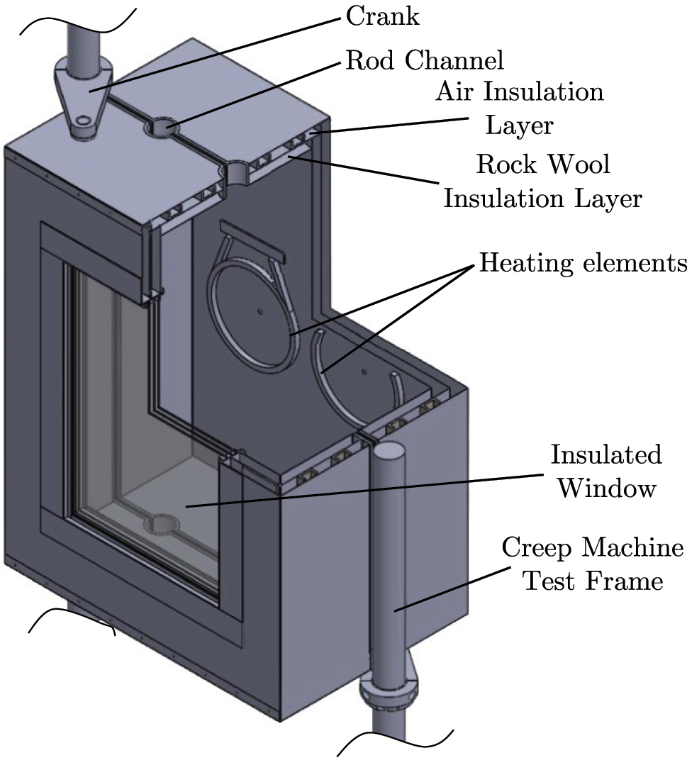
Designed thermal chamber for the proposed creep testing machine.
A thermocouple type T temperature transducer was chosen to measure the temperature inside the thermal chamber, since this element can work at a temperature range between −270 °C and 400 °C [99]. An industrial temperature controller is adopted to control the temperature inside the chamber, and this controller makes use of time-proportional control to emulate a PID controller. In this manner, a relay is switched at high frequency, with the help of a solid-state relay that endures a high number of commutations. This industrial controller can also control a cryogenic solenoid valve, thus defining the flow of coolant entering the chamber [97].
5.2 Scientific output
Creep testing of adhesives and bonded joints is highly relevant since, for many applications, they are often subjected to constant loads for long periods of time, which allows viscoelastic effects to dominate the material behaviour. For example, adhesives are often used to bond equipment to vertical panels, which exposes the adhesive to a low, but constant shear creep loads that will cause excessive strains and fail the structure. The development of practical and easy to use creep testing machines, such as the one described above, has enabled the AJPU to produce significant research work in this field. In one such work, the creep behaviour of pressure sensitive adhesives has been determined in a preliminary analysis, allowing to understand how these materials undergo creep failure and what are the conditions that drive this phenomenon [92]. Further work is being undertaken to expand on this, targeting more detailed characterization of the creep behaviour under multiple conditions, including cyclic loads and temperature, and the development of damage models of the creep behaviour. Simpler models to assess the long-term creep strain have already been developed, using experimental data, determined at varied temperatures to create master-curves [100]. Other works have also been carried out to determine the effect of adding creep inhibiting additives to adhesive layer, carrying out experimental analysis and numerical modelling on the material behaviour [101], [102].
6 Conclusions
This paper provides an informed description of unconventional testing machines, which were designed, manufactured, assembled and validated by the AJPU research unit. In this manner, the designed experimental aparatuses allow the testing of adhesive joints under impact and high strain-rate conditions, in torsion conditions, or in creep conditions (with varying temperature). It is noted that some of these machines required the development of novel operating systems, such as the torsion machine or the pneumatic actuator of the tensile and compressive SHPB apparatus. Consequently, some of these systems were under the protection of Provisional Portuguese Patent status, or of a Know how intellectual property rights status.
The machines, which have been designed during the course of these works have shown to be highly valuable for the scientific activities carried out by the research group in the field of advanced joining processes. This has enabled the development of novel material characterization techniques, allowing to accurately model complex processes.
Furthermore, the experience provided to master students, during the development of the testing equipment shown, has allowed them to develop their machine design skills and reach the work market better prepared for the needs of the industry, while providing an added value to their master thesis.
Funding source: Fundação para a Ciência e a Tecnologia
Award Identifier / Grant number: 2021.07689.BD
Award Identifier / Grant number: CEECIND/03276/2018
-
Research ethics: Not applicable.
-
Author contributions: The authors have accepted responsibility for the entire content of this manuscript and approved its submission.
-
Competing interests: The authors state no conflict of interest.
-
Research funding: The authors gratefully acknowledge the funding of grants 2021.07689.BD and CEECIND/03276/2018, which are provided by Fundação para a Ciência e Tecnologia (FCT).
-
Data availability: Not applicable.
References
[1] G. Keller, Academic Strategy: The Management Revolution in American Higher Education, 1st ed. Oxford, England, United Kingdom, Johns Hopkins University Press, 1983.Search in Google Scholar
[2] E. A. S. Marques, R. J. C. Carbas, and L. F. M. da Silva, “Characterizing academic engineering research groups: a case study of the advanced joining processes unit,” U. Porto J. Eng., vol. 8, no. 6, pp. 76–89, 2022. https://doi.org/10.24840/2183-6493_008.006_0006.Search in Google Scholar
[3] L. F. M. da Silva, A. Öchsner, and R. D. Adams, Handbook of Adhesion Technology, 2nd ed. New York, NY, United States, Springer International Publishing AG, 2018.10.1007/978-3-319-55411-2Search in Google Scholar
[4] J. Antelo, A. Akhavan-Safar, R. Carbas, E. Marques, R. Goyal, and L. da Silva, “Replacing welding with adhesive bonding: an industrial case study,” Int. J. Adhes. Adhes., vol. 113, p. 103064, 2022, https://doi.org/10.1016/j.ijadhadh.2021.103064.Search in Google Scholar
[5] F. Delzendehrooy, et al.., “A comprehensive review on structural joining techniques in the marine industry,” Compos. Struct., vol. 289, p. 115490, 2022, https://doi.org/10.1016/j.compstruct.2022.115490.Search in Google Scholar
[6] E. Marques, L. da Silva, and M. Flaviani, “Testing and simulation of mixed adhesive joints for aerospace applications,” Compos. B Eng., vol. 74, pp. 123–130, 2015, https://doi.org/10.1016/j.compositesb.2015.01.005.Search in Google Scholar
[7] T. Wei, N. Jingxin, M. Wenlong, W. Guangbin, and F. Yao, “Effects of hygrothermal aging on the mechanical properties of aluminum alloy adhesive joints for high-speed train applications,” J. Adhes., vol. 98, no. 3, pp. 227–256, 2022. https://doi.org/10.1080/00218464.2020.1828878.Search in Google Scholar
[8] P. Fernandes, L. Poggenburg-Harrach, C. Nagel, and V. Beber, “Lifetime calculation of adhesively bonded joints under proportional and non-proportional multiaxial fatigue loading: a combined critical plane and critical distance approach,” J. Adhes., vol. 98, no. 6, pp. 780–809, 2022. https://doi.org/10.1080/00218464.2021.2007088.Search in Google Scholar
[9] F. C. Sousa, A. Akhavan-Safar, R. Goyal, and L. F. M. da Silva, “Fatigue life estimation of adhesive joints at different mode mixities,” J. Adhes., vol. 98, no. 1, pp. 1–23, 2022. https://doi.org/10.1080/00218464.2020.1804376.Search in Google Scholar
[10] C. S. P. Borges, et al.., “Influence of water and surfactant contamination on the mechanical and chemical properties of a silicone adhesive before and after curing,” J. Adhes., vol. 99, no. 6, pp. 1071–1098, 2023. https://doi.org/10.1080/00218464.2022.2082291.Search in Google Scholar
[11] V. Loreiro, G. Ramalho, A. Tenreiro, A. M. Lopes, and L. da Silva, “Feature extraction and visualization for damage detection on adhesive joints, utilizing lamb waves and supervised machine learning algorithms,” Proc. Inst. Mech. Eng. C Mech. Eng. Sci., vol. 236, no. 16, pp. 8842–8855, 2022. https://doi.org/10.1177/09544062221086410.Search in Google Scholar
[12] L. M. Oliveira, S. Esteves, A. F. Tenreiro, J. R. Matos, J. da Sobral, and J. P. T. Pereira, Systems Design for FRP Hybrid AM, Vol. 129 of Advanced Structured Materials, Cham, Switzerland, Springer International Publishing, 2020, Ch. 5, pp. 173–201.10.1007/978-3-030-44522-5_5Search in Google Scholar
[13] L. M. Oliveira, S. Esteves, A. F. Tenreiro, J. R. Matos, J. da Sobral, and J. P. T. Pereira, Case Studies, Vol. 129 of Advanced Structured Materials, Cham, Switzerland, Springer International Publishing, 2020, Ch. 9, pp. 297–309.10.1007/978-3-030-44522-5_9Search in Google Scholar
[14] W. Beitz and K.-H. Kuttner, Dubbel: Handbook of Mechanical Engineering, 1st ed. London, England, United Kingdom, Springer-Verlag London, 1994.10.1007/978-1-4471-3566-1Search in Google Scholar
[15] P. Sivák and D. Hroncová, “State-space model of a mechanical system in matlab/simulink,” Proc. Eng., vol. 48, pp. 629–635, 2012, https://doi.org/10.1016/j.proeng.2012.09.563.Search in Google Scholar
[16] H. Mistry, D. S. Laila, and M. da Foo, “Teaching embedded control system design of electromechanical devices using a lab-scale smart farming system,” Int. J. Mech. Eng. Educ., 2023, https://doi.org/10.1177/03064190231190052.Search in Google Scholar
[17] L. F. da Silva and R. D. Adams, “Measurement of the mechanical properties of structural adhesives in tension and shear over a wide range of temperatures,” J. Adhes. Sci. Technol., vol. 19, no. 2, pp. 109–141, 2005. https://doi.org/10.1163/1568561053148449.Search in Google Scholar
[18] A. D. Crocombe and R. D. Adams, “Influence of the spew fillet and other parameters on the stress distribution in the single lap joint,” J. Adhes., vol. 13, no. 2, pp. 141–155, 1981. https://doi.org/10.1080/00218468108073182.Search in Google Scholar
[19] R. Créac’hcadec, L. Sohier, B. Cellard, and B. Gineste, “A stress concentration-free bonded arcan tensile compression shear test specimen for the evaluation of adhesive mechanical response,” Int. J. Adhes. Adhes., vol. 61, pp. 81–92, 2015, https://doi.org/10.1016/j.ijadhadh.2015.05.003.Search in Google Scholar
[20] F. Kadioglu, L. F. Vaughn, F. J. Guild, and R. D. Adams, “Use of the thick adherend shear test for shear stress-strain measurements of stiff and flexible adhesives,” J. Adhes., vol. 78, no. 5, pp. 355–381, 2002. https://doi.org/10.1080/00218460211818.Search in Google Scholar
[21] M. A. Dantas, A. M. Carbas, R. J. C. Lopes, C. M. da Silva, E. A. S. Marques, and L. F. M. da Silva, Novel Torsion Machine to Test Adhesive Joints, Lecture Notes in Mechanical Engineering, Springer, Singapore, 2021, Ch. 3, pp. 31–56.10.1007/978-981-15-6767-4_3Search in Google Scholar
[22] C. Kang, J. J. M. Machado, Y. Sekiguchi, M. Ji, C. Sato, and M. Naito, “A butt shear joint (BSJ) specimen for high throughput testing of adhesive bonds,” J. Adhes., vol. 99, pp. 1–17, 2023, https://doi.org/10.1080/00218464.2023.2170794.Search in Google Scholar
[23] T. Tan, et al.., “Investigating fracture behavior of polymer and polymeric composite materials using spiral notch torsion test,” Eng. Fract. Mech., vol. 101, pp. 109–128, 2013, part of Special Issue: Fracture of Polymers, Composites and Adhesives, https://doi.org/10.1016/j.engfracmech.2012.07.007.Search in Google Scholar
[24] J. A. Wang, K. C. Kiu, D. E. McCabe, and S. A. David, “Torsion fatigue response of self-healing poly(dimethylsiloxane) elastomers,” Fatig. Fract. Eng. Mater. Struct., vol. 23, no. 11, pp. 917–927, 2000. https://doi.org/10.1046/j.1460-2695.2000.00352.x.Search in Google Scholar
[25] J.-A. Wang, “J-integral measured from experimental torque load versus torque-ends rotation angle obtained from a spiral notch torsion test,” Theor. Appl. Fract. Mech., vol. 109, p. 102721, 2020, https://doi.org/10.1016/j.tafmec.2020.102721.Search in Google Scholar
[26] A. Fabregat-Sanjuan, F. F. Piera, and S. D. L. F. López, “An experimental approach to the thermomechanical characterization of a niticu shape memory alloy using strain gauges,” Proc. Inst. Mech. Eng. Part L, vol. 231, nos. 1–2, pp. 113–121, 2017. https://doi.org/10.1177/1464420716669533.Search in Google Scholar
[27] Zwick Roell, “Product information – TorsionLine TL 020/TL 200/TL 500 torsion testing machines,” 2012.Search in Google Scholar
[28] INSTRON, “MT MicroTorsion series – medium-capacity torsion testing systems,” 2014.Search in Google Scholar
[29] T. Brinz, J. Lewis, and T. Geiger, “Device for testing material properties with regard to combined tensile and shear loads, in particular for testing adhesives,” 2008. Available at: https://patents.google.com/patent/US20050193829A1/en?oq=US2005193829A1.Search in Google Scholar
[30] J. L. A. Ambriz, G. M. D. Almaraz, V. Juarez, E. C. Gomez, and I. F. Zuñiga, “Design and construction of a torsion fatigue machine: torsion fatigue tests on two industrial aluminum alloys,” UPB Sci. Bull. D: Mech. Eng., vol. 79, no. 2, pp. 169–182, 2017.Search in Google Scholar
[31] F. M. P. Bustos and C. A. A. Vargas, “Design and construction of a torsional fatigue testing machine operated by inertial loads,” DYNA, vol. 79, pp. 46–55, 2012.Search in Google Scholar
[32] V. Goanţă, C. Morăraş, and I. Blanari, “Device for testing at combined cyclic fatigue loading by tensile and torsion, attachable to the universal testing machine,” Exp. Tech., vol. 46, no. 1, pp. 179–186, 2022. https://doi.org/10.1007/s40799-021-00471-3.Search in Google Scholar
[33] K. Ogata, Modern Control Engineering, 5th ed. Upper Saddle River, NJ, United States, Prentice Hall, 2010.Search in Google Scholar
[34] M. A. Dantas, R. J. C. Carbas, E. A. S. Marques, D. Kushner, and L. F. M. da Silva, “Flexible tubular metal-polymer adhesive joints under torsion loading,” Int. J. Adhes. Adhes., vol. 105, p. 102787, 2021, https://doi.org/10.1016/j.ijadhadh.2020.102787.Search in Google Scholar
[35] R. J. C. Carbas, M. A. Dantas, E. A. S. Marques, and L. F. M. da Silva, “Effect of the adhesive thickness on butt adhesive joints under torsional loads,” J. Adv. Join. Process., vol. 3, p. 100061, 2021, https://doi.org/10.1016/j.jajp.2021.100061.Search in Google Scholar
[36] M. A. Dantas, R. Carbas, E. A. S. Marques, M. P. L. Parente, D. Kushner, and L. F. M. da Silva, “Numerical study of flexible tubular metal-polymer adhesive joints,” J. Adhes., vol. 98, no. 2, pp. 131–153, 2022. https://doi.org/10.1080/00218464.2020.1822173.Search in Google Scholar
[37] S. Sharma, V. M. Chavan, R. G. Agrawal, R. J. Patel, R. Kapoor, and J. K. Chakravartty, “Split-Hopkinson pressure bar: an experimental technique for high strain rate tests,” Bhabha Atomic Research Centre, Mumbai, India, Technical Report BARC/2011/E/013, 2011.Search in Google Scholar
[38] W. Chen and B. Song, Split Hopkinson (Kolsky) Bar, Mechanical Engineering Series, Boston, MA, Springer US, 2011.10.1007/978-1-4419-7982-7Search in Google Scholar
[39] A. F. G. Tenreiro, C. M. Silva, A. M. Lopes, P. D. Nunes, R. J. Carbas, and L. F. da Silva, “Design of a new pneumatic impact actuator of a split Hopkinson pressure bar (SHPB) setup for tensile and compression testing of structural adhesives,” Mech. Mach. Theor., vol. 159, p. 104289, 2021, https://doi.org/10.1016/j.mechmachtheory.2021.104289.Search in Google Scholar
[40] C. Sato, “Testing of adhesively bonded joints by split Hopkinson bar technique,” in The Kolsky-Hopkinson Bar Machine, R. Othman, Ed., Cham, Switzerland, Springer International Publishing, 2018, pp. 273–282.10.1007/978-3-319-71919-1_10Search in Google Scholar
[41] U. S. Lindholm and L. M. Yeakley, “High strain-rate testing: tension and compression,” Exp. Mech., vol. 8, no. 1, pp. 1–9, 1968. https://doi.org/10.1007/BF02326244.Search in Google Scholar
[42] T. Nicholas, “Tensile testing of materials at high rates of strain,” Exp. Mech., vol. 21, pp. 177–185, 1981, https://doi.org/10.1007/BF02326644.Search in Google Scholar
[43] J. Harding and L. M. Welsh, “A tensile testing technique for fibre-reinforced composites at impact rates of strain,” J. Mater. Sci., vol. 18, pp. 1810–1826, 1983, https://doi.org/10.1007/BF00542078.Search in Google Scholar
[44] F. E. Hauser, “Techniques for measuring stress-strain relations at high strain rates,” Exp. Mech., vol. 6, pp. 395–402, 1966, https://doi.org/10.1007/BF02326284.Search in Google Scholar
[45] S. Nemat-Nasser, J. B. Isaacs, and J. E. Starrett, “Hopkinson techniques for dynamic recovery experiments,” Proc. Math. Phys. Sci., vol. 435, no. 1894, pp. 371–391, 1991.10.1098/rspa.1991.0150Search in Google Scholar
[46] R. Gerlach, C. Kettenbeil, and N. Petrinic, “A new split Hopkinson tensile bar design,” Int. J. Impact Eng., vol. 50, pp. 63–67, 2012, https://doi.org/10.1016/j.ijimpeng.2012.08.004.Search in Google Scholar
[47] R. A. González-Lezcano and J. M. del Río, “Numerical analysis of the influence of the damping rings’ dimensions on interrupted dynamic tension experiment results,” J. Strain Anal. Eng. Des., vol. 50, no. 8, pp. 594–613, 2015. https://doi.org/10.1177/0309324715601550.Search in Google Scholar
[48] Y. Miao, B. Du, C. Ma, H. Haitao, and Q. Deng, “Some fundamental problems concerning the measurement accuracy of the Hopkinson tension bar technique,” Meas. Sci. Technol., vol. 30, p. 055009, 2019, https://doi.org/10.1088/1361-6501/ab01b5.Search in Google Scholar
[49] A. J. Boland, et al.., “Development of a split Hopkinson pressure bar machine for high strain rate testing of bonded joints,” J. Test. Eval., vol. 50, no. 1, p. 20200677, 2022. https://doi.org/10.1520/JTE20200677.Search in Google Scholar
[50] P. D. P. Nunes, E. A. S. Marques, A. Akhavan-Safar, C. S. P. Borges, R. J. C. Carbas, and L. F. M. da Silva, “An update on the development of techniques for the determination and modelling of the impact behaviour of adhesives and bonded structures used in the automotive sector,” Proc. Inst. Mech. Eng. – Part D J. Automob. Eng., vol. 237, pp. 3007–3023, 2022, https://doi.org/10.1177/09544070221135902.Search in Google Scholar
[51] B. S. Moreira, et al.., “Numerical design of a thread-optimized gripping system for lap joint testing in a split Hopkinson apparatus,” Sensors, vol. 23, no. 4, p. 2273, 2023. https://doi.org/10.3390/s23042273.Search in Google Scholar PubMed PubMed Central
[52] P. D. P. Nunes, E. A. S. Marques, R. J. C. Carbas, A. Akhavan-Safar, and L. F. M. da Silva, “Quasi-static and intermediate test speed validation of shpb specimens for the determination of mode i, mode ii fracture toughness of structural epoxy adhesives,” Eng. Fract. Mech., vol. 262, p. 108231, 2022, https://doi.org/10.1177/09544070221135902.Search in Google Scholar
[53] B. D. Simões, et al.., “Determination of mode I cohesive law of structural adhesives using the direct method,” J. Adhes., vol. 99, no. 10, pp. 1650–1677, 2023. https://doi.org/10.1080/00218464.2022.2152677.Search in Google Scholar
[54] ISO 6358:1989, Pneumatic Fluid Power – Components Using Compressible Fluids – Determination of Flow-Rate Characteristics, Geneva, CH, Standard, International Organization for Standardization, 1989.Search in Google Scholar
[55] X. Brum, “Commandes linéaires et non linéaires en électropneumatique. méthodologies et applications,” Ph.D., Institut National des Sciences Appliquées de Lyon, Lyon, France, 1999.Search in Google Scholar
[56] J. F. Carneiro and F. Gomes de Almeida, “Reduced-order thermodynamic models for servo-pneumatic actuator chambers,” Proc. Inst. Mech. Eng. Part I: J. Syst. Control Eng., vol. 220, no. 4, pp. 301–314, 2006. https://doi.org/10.1243/09596518JSCE203.Search in Google Scholar
[57] L. C. F. Moreira, “Caracterização experimental de um atuador pneumático de baixo atrito,” Master’s thesis, Faculdade de Engenharia da Universidade do Porto, Porto, Portugal, 2012.Search in Google Scholar
[58] ACE – Automation Control Equipment, “Damping technology – main catalogue,” 2017.Search in Google Scholar
[59] U. Zencker and R. Clos, “Limiting conditions for compression testing of flat specimens in the split Hopkinson pressure bar,” Exp. Mech., vol. 39, no. 4, pp. 343–348, 1999. https://doi.org/10.1007/BF02329815.Search in Google Scholar
[60] I. W. Hall and M. Guden, “Split Hopkinson pressure bar compression testing of an aluminum alloy: effect of lubricant type,” J. Mater. Sci. Lett., vol. 22, pp. 1533–1535, 2003. https://doi.org/10.1023/A:1026167517837 10.1023/A:1026167517837Search in Google Scholar
[61] B. Song, W. Chen, S. T. Montgomery, and M. J. Forrestal, “Mechanical response of an alumina-filled epoxy at various strain rates,” J. Compos. Mater., vol. 43, no. 14, pp. 1519–1536, 2009. https://doi.org/10.1177/0021998308337741.Search in Google Scholar
[62] X. Nie, B. Song, W. W. Chen, and T. Weerasooriya, “Dynamic tensile testing of soft materials,” Exp. Mech., vol. 49, pp. 451–458, 2008, https://doi.org/10.1007/s11340-008-9133-5.Search in Google Scholar
[63] N. Ledford, et al.., “Investigations on specimen design and mounting for split Hopkinson tension bar (SHTB) experiments,” EPJ Web Conf., vol. 94, p. 021049, 2015, https://doi.org/10.1051/epjconf/20159401049.Search in Google Scholar
[64] W. Deng, Q. Luo, and J. B. Kim, “A numerical investigation into the tensile split Hopkinson pressure bars test for sheet metals,” Appl. Mech. Mater., vol. 421, pp. 464–467, 2013, https://doi.org/10.4028/www.scientific.net/AMM.421.464.Search in Google Scholar
[65] S. C. Constantino, “Aluminium FSW joints under high strain rate tensile testing,” Master’s thesis, University of Porto, 2016.Search in Google Scholar
[66] I. P. da Qualidade, Roscas métricas trapezoidais ISO – Perfil de base e perfis de máximo de matéria, Caparica, Portugal, Standard, Instituto Português da Qualidade, nP ISO 2901:2013, 2013.Search in Google Scholar
[67] J. J. M. Machado, E. A. S. Marques, and L. F. M. da Silva, “Adhesives and adhesive joints under impact loadings: an overview,” J. Adhes., vol. 94, no. 6, pp. 421–452, 2018. https://doi.org/10.1080/00218464.2017.1282349.Search in Google Scholar
[68] C. Hu, G. Huang, and C. Li, “Experimental and numerical study of low-velocity impact and tensile after impact for cfrp laminates single-lap joints adhesively bonded structure,” Materials, vol. 13, no. 4, p. 1016, 2021. https://doi.org/10.3390/ma14041016.Search in Google Scholar PubMed PubMed Central
[69] R. D. Adams, “Quality assurance, especially in adhesive bonding,” Proc. Inst. Mech. Eng. – Part D J. Automob. Eng., vol. 237, pp. 1–17, 2022, https://doi.org/10.1177/09544070221115975.Search in Google Scholar
[70] N. D. D. Silva, J. J. M. Machado, E. A. S. Marques, P. M. G. P. Moreira, and L. F. M. da Silva, “Experimental and numerical study of the dynamic response of an adhesively bonded automotive structure,” Proc. Inst. Mech. Eng. – Part D J. Automob. Eng., vol. 234, no. 14, pp. 3385–3397, 2020. https://doi.org/10.1177/0954407020931699.Search in Google Scholar
[71] M. W. Money, “Instrumental falling weight impact testing of polymethacrylate and high density polyethylene,” Ph.D., Queen Mary College, University of London, London, England, United Kingdom, 1988.Search in Google Scholar
[72] H. Wang, T.-T. Li, L. Wu, C.-W. Lou, and J.-H. Lin, “Multifunctional, polyurethane-based foam composites reinforced by a fabric structure: preparation, mechanical, acoustic, and EMI shielding properties,” Materials, vol. 11, no. 11, p. 2085, 2018. https://doi.org/10.3390/ma11112085.Search in Google Scholar PubMed PubMed Central
[73] T. M. Shuaeib, S. V. Wong, K. S. Tan, A. M. S. Hamouda, R. S. R. Umar, and M. M. H. M. Ahmad, “Drop weight testing rig analysis and design,” Pertanika J. Sci. Technol., vol. 12, no. 2, pp. 159–175, 2004.Search in Google Scholar
[74] Zwick Roell, “Product information – amsler HIT230F drop weight tester for multiaxial puncture test,” 2021.Search in Google Scholar
[75] D. R. Ambur, C. B. Prasad, and W. A. Waters, “A dropped-weight apparatus for low-speed impact testing of composite structures,” Exp. Mech., vol. 35, no. 1, pp. 77–82, 1995. https://doi.org/10.1007/BF02325839.Search in Google Scholar
[76] X. X. Zhang, G. Ruiz, and R. C. Yu, “A new drop-weight impact machine for studying fracture processes in structural concrete: new drop-weight impact machine,” Strain, vol. 46, no. 3, pp. 252–257, 2008. https://doi.org/10.1111/j.1475-1305.2008.00574.x.Search in Google Scholar
[77] T. Adachi, T. Ozawa, and Y. Ishii, “Development of small drop-weight testing machine based on electromagnetic induction,” Exp. Mech., vol. 61, pp. 1333–1342, 2021, https://doi.org/10.1007/s11340-021-00750-5.Search in Google Scholar
[78] C. Canudas de Wit, H. Olsson, K. Astrom, and P. Lischinsky, “A new model for control of systems with friction,” IEEE Trans. Automat. Control, vol. 40, no. 3, pp. 419–425, 1995. https://doi.org/10.1109/9.376053.Search in Google Scholar
[79] K. Johanastrom and C. Canudas-de Wit, “Revisiting the lugre friction model,” IEEE Control Syst. Mag., vol. 28, no. 6, pp. 101–114, 2008. https://doi.org/10.1109/MCS.2008.929425.Search in Google Scholar
[80] J. Yang, A. Plummer, and Y. Xue, “Dynamic friction modelling without drift and its application in the simulation of a valve controlled hydraulic cylinder system,” J. Adv. Mech. Des. Syst. Manuf., vol. 8, no. 6, pp. 00214–00218, 2014. https://doi.org/10.1299/jamdsm.2014jamdsm0075.Search in Google Scholar
[81] D. P. C. Antunes, et al.., “Development of a drop weight machine for adhesive joint testing,” J. Test. Eval., vol. 49, no. 3, p. 20190147, 2021. https://doi.org/10.1520/JTE20190147.Search in Google Scholar
[82] M. dos Reis, R. J. C. Carbas, E. A. S. Marques, and L. F. M. da Silva, “Functionally graded adhesive joints under impact loads,” Proc. Inst. Mech. Eng. – Part D J. Automob. Eng., vol. 235, no. 13, pp. 3270–3281, 2021. https://doi.org/10.1177/09544070211004505.Search in Google Scholar
[83] D. Rosendo, G. Viana, R. J. C. Carbas, E. A. S. Marques, and L. F. M. da Silva, “Effect of temperature and moisture on the iMPACT behaviour of adhesive joints for the automobile industry,” J. Appl. Comput. Mech., vol. 7, no. 3, pp. 1488–1500, 2021. https://doi.org/10.22055/JACM.2021.36089.2793.Search in Google Scholar
[84] M. Perez, A. Akhavan-Safar, R. J. C. Carbas, E. A. S. Marques, S. Wenig, and L. F. M. da Silva, “Loading rate and temperature interaction effects on the mode I fracture response of a ductile polyurethane adhesive used in the automotive industry,” Materials, vol. 15, no. 24, p. 8948, 2022. https://doi.org/10.3390/ma15248948.Search in Google Scholar PubMed PubMed Central
[85] C. Borges, et al.., “Influence of mode mixity and loading rate on the fracture behaviour of crash resistant adhesives,” Theor. Appl. Fract. Mech., vol. 107, p. 102508, 2020, https://doi.org/10.1016/j.tafmec.2020.102508.Search in Google Scholar
[86] K. W. Allen and M. E. R. Shanahan, “The creep behaviour of structural adhesive joints – I,” J. Adhes., vol. 7, no. 3, pp. 161–174, 1975. https://doi.org/10.1080/00218467508075048.Search in Google Scholar
[87] K. W. Allen and M. E. R. Shanahan, “The creep behaviour of structural adhesive joints – II,” J. Adhes., vol. 8, no. 1, pp. 43–56, 1976. https://doi.org/10.1080/00218467608075069.Search in Google Scholar
[88] M. Emara, L. Torres, M. Baena, C. Barris, and M. Moawad, “Effect of sustained loading and environmental conditions on the creep behavior of an epoxy adhesive for concrete structures strengthened with CFRP laminates,” Compos. B Eng., vol. 129, pp. 88–96, 2017, https://doi.org/10.1016/j.compositesb.2017.07.026.Search in Google Scholar
[89] E. Ernault, J. Diani, and Q. Schmid, “Single-lap joint creep behaviour of two soft adhesives,” J. Adhes., vol. 99, pp. 1282–1298, 2023, https://doi.org/10.1080/00218464.2022.2100254.Search in Google Scholar
[90] W. Tan, J.-X. Na, and Z.-F. Zhou, “Effect of temperature and humidity on the creep and aging behavior of adhesive joints under static loads,” J. Adhes., vol. 99, pp. 672–690, 2023, https://doi.org/10.1080/00218464.2022.2044319.Search in Google Scholar
[91] S. Houshyar, R. A. Shanks, and A. Hodzic, “Tensile creep behaviour of polypropylene fibre reinforced polypropylene composites,” Polym. Test., vol. 24, pp. 257–264, 2005, https://doi.org/10.1016/j.polymertesting.2004.07.003.Search in Google Scholar
[92] B. D. Simões, et al.., “An exploratory study on determining and modeling the creep behavior of an acrylic pressure-sensitive adhesive,” Materials, vol. 16, p. 2029, 2023, https://doi.org/10.3390/ma16052029.Search in Google Scholar PubMed PubMed Central
[93] W.-H. Wang, H.-B. Huang, H.-H. Du, and W. Haigang, “Effects of fiber size on short-term creep behavior of wood fiber/HDPE composites,” Polym. Eng. Sci., vol. 55, pp. 693–700, 2015, https://doi.org/10.1002/pen.23935.Search in Google Scholar
[94] Z. Ahmad, M. Ansell, D. Smedley, and P. Md Tahir, “Creep behavior of epoxy-based adhesive reinforced with nanoparticles for bonded-in timber connection,” J. Mater. Civ. Eng., vol. 24, pp. 825–831, 2012, https://doi.org/10.1061/(ASCE)MT.1943-5533.0000453.Search in Google Scholar
[95] G. N. Bezerra, et al.., “Development of a multi-station creep machine for adhesive joint testing,” J. Test. Eval., vol. 50, no. 5, p. 20210730, 2022. https://doi.org/10.1520/JTE20210730.Search in Google Scholar
[96] FESTO, “Proportional pressure regulators VPPX,” 2017.Search in Google Scholar
[97] M. B. Janeira, C. M. Da Silva, A. M. Lopes, and L. F. M. Da Silva, “Thermal chamber for adhesives creep multi-station testing machine,” U. Porto J. Eng., vol. 6, no. 2, pp. 1–10, 2020. https://doi.org/10.24840/2183-6493_006.002_0001.Search in Google Scholar
[98] T. L. Bergman, A. S. Lavine, F. P. Incropera, and D. P. DeWitt, Fundamentals of Heat and Mass Transfer, 8th ed. Hoboken, New Jersey, United States, John Wiley & Sons, 2018.Search in Google Scholar
[99] R. L. Powell, et al.., Thermocouple Reference Tables Based on the IPTS-68, 1st ed. Washington D. C., District of Columbia, United States, US National Bureau of Standards, 1974.10.6028/NBS.MONO.125supp1Search in Google Scholar
[100] E. A. S. Marques, R. J. C. Carbas, F. Silva, L. F. M. da Silva, D. P. S. de Paiva, and F. D. Magalhães, “Use of master curves based on time-temperature superposition to predict creep failure of aluminium-glass adhesive joints,” Int. J. Adhes. Adhes., vol. 74, pp. 144–154, 2017, https://doi.org/10.1016/j.ijadhadh.2016.12.007.Search in Google Scholar
[101] A. Khabazaghdam, B. Behjat, M. Yazdani, L. F. M. da Silva, E. A. S. Marques, and X. Shang, “Creep behaviour of a graphene-reinforced epoxy adhesively bonded joint: experimental and numerical investigation,” J. Adhes., vol. 97, no. 13, pp. 1189–1210, 2021. https://doi.org/10.1080/00218464.2020.1742114.Search in Google Scholar
[102] A. Khabaz-Aghdam, B. Behjat, L. F. M. da Silva, and E. A. S. Marques, “A new theoretical creep model of an epoxy-graphene composite based on experimental investigation: effect of graphene content,” J. Compos. Mater., vol. 54, no. 18, pp. 2461–2472, 2020. https://doi.org/10.1177/0021998319895806.Search in Google Scholar
© 2024 the author(s), published by De Gruyter, Berlin/Boston
This work is licensed under the Creative Commons Attribution 4.0 International License.
Articles in the same Issue
- Frontmatter
- Research Articles
- Error analysis of inertial navigation based on quaternion approach
- Novel robot arm concept for lightweighting high-performance machinery
- On the design of unconventional testing machines for engineering testing – the case study of advanced joining processes unit