Numerical and experimental study of the dynamic factor of the dynamic load on the urban railway
-
Tran Anh Dung
 ,
Mai Van Tham
,
Mai Van Tham

Abstract
This paper presents simulation calculations and experimental measurements to determine the dynamic load factor (DLF) of train on the urban railway in Vietnam. Simulation calculations are performed by SIMPACK software. Dynamic measurement experiments were conducted on Cat Linh – Ha Dong line. The simulation and experimental results provide the DLF values with the largest difference of 2.46% when the train speed varies from 0 km/h to 80 km/h
1 Introduction
Dynamic load is an important value in the railway design process. Thus, accurate study of the DLF will lead to safe and economical designs. However, determining the DLF is a rather complicated problem because of the interaction between rail and moving vehicles.
The dynamic load is generally expressed as a function of the static load (Eq. 1) [1]
Where Pd is the dynamic wheel load, ∅ is the dynamic wheel load factor (∅ > 1), and Ps is the static wheel load.
Studies by authors around the world have published research results on dynamic load of railway. In 1953, Talbot [2] had given a dynamic load factor that relates to train speed and wheel diameter for heavy haul railway with the train speed less than 80 km/h. In 1969, Indian Railways had proposed dynamic load factor for narrow gauge track incorporates track modulus and train speed [3]. Eisenmann (1972) had used dynamic load factor for high speed railway track that incorporates train speed and the condition of the track [4]. The Office of Research and Experiments (ORE) of the International Union of Railways and Birmann [5] had proposed dynamic load factor for speeds up to 200 km/h incorporates the track geometry, vehicle suspension, vehicle speed, vehicle center of gravity, age of track, curve radius, super-elevation, and cant deficiency. The Germany Railways (1943) using an equation with the train speed is no more than 200 km/h to calculate the dynamic load factor only using train speed [6]. The dynamic load factor formula is used for South African Railways is similar to the Talbot formula, but is calculated for narrow gauge track [2]. Clarke formula algebraically combines the Talbot and Indian Railways dynamic load factors [7]. In 1968, a dynamic load factor only depended on the train speed was prepared for the Washington Metropolitan Area Transit Authority (WMATA) and used in subsequently recommended standards for transit trackwork [8]. In 2010, Sadeghi had proposed a dynamic load factor in Iran. This factor depends on train speed [9]. The speed of the train is no more 200km/h. The use of the AREMA recommendation for dynamic impact factor is suggested for the railway with the train speed from 32 km/ h to 193 km/ h [10]. The China Railways proposed dynamic load factors that depend on train speed and wheel load shift coefficient in curves. This factor is used for high speed railway [11]. In 2017, Leonid and Andrey had researched dynamic live load factor for bridge structures on High speed railway [12].
In this study, the authors studied the DLF for the urban railway based on field measurement and simulation calculations. The strain gage is used to measure relative deformation. Simulation calculations are implemented by SIMPACK software.
2 Experimental method to determinate DLF
2.1 Test equipments
The rail is mounted the equipment to measure deformation. Relative deformation was measured by the strain gage with length 10mm. Strain gage was placed at the bottom center of the rail foot (Figure 1).

The strain gage
2.2 Load test arrangements
Test loads are trains on Cat Linh – Ha Dong urban railway line as Figure 2.

The train of Cat Linh – Ha Dong urban railway line
Each train includes 4 cars [13] with the following set-up method: + Tc-M + M-Tc such as Figure 3, in which:

Model of the train
“+”: semi-automatic central buffer coupler
“−”: Semi-permanent central buffer coupler
“M”: motor car
“Tc”: trailer car
Load arrangement of the train is set up such as Figure 4

Model of test train load
2.3 Test results
Figure 5 shows the dynamic deformation time-history curves of the rail foot in the first test point on Cat Linh – Ha Dong urban railway line with train speed V = 30 km/h. The maximum of dynamic deformation is 0.00011732.

Dynamic deformation versus time for train speed V = 30km/h
Figure 6 shows the dynamic deformation time-history curves of the rail foot in the second test point on Cat Linh – Ha Dong urban railway line with train speed V = 50 km/h. The maximum of dynamic deformation is 0.000127.

Dynamic deformation versus time for train speed V = 50km/h
Figure 7 shows the dynamic deformation time-history curves of the rail foot in the third test point on Cat Linh – Ha Dong urban railway line with train speed V = 80 km/h. The maximum of dynamic deformation is 0.000145.
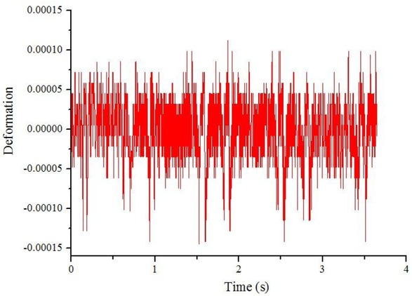
Dynamic deformation versus time for train speed V = 80km/h
Measuring the static deformation of the rail we have the following results:
Table of results of static deformation
| No. | Measurement times | Static deformation |
|---|---|---|
| 1 | The first | 0.00010735 |
| 2 | The second | 0.00010519 |
| 3 | The third | 0.00010004 |
| Average value | 0.00010419 |
Some typical results of the dynamic load factors are depicted in the form of graphs comprising load histories under different train speeds (Figure 8).

Dynamic load factors increasing due to speed for urban railway
By using linear regression analysis of the DLF. Using Minitab simulation software. The results from the minitab software are as follows
Regression equation
Coefficients
| Term | Coef | SE Coef | T-Value | P-Value | VIF |
|---|---|---|---|---|---|
| Constant | 0.9909 | 0.0124 | 79.94 | 0.000 | |
| V | 0.004853 | 0.000250 | 19.38 | 0.003 | 1.00 |
Model Summary
| S | R-sq | R-sq(adj) | R-sq(pred) |
|---|---|---|---|
| 0.0146026 | 99.47% | 99.21% | 96.25% |
Analysis of variance
| Source | DF | Adj SS | Adj MS | F-Value | P-Value |
|---|---|---|---|---|---|
| Regression | 1 | 0.080074 | 0.080074 | 375.52 | 0.003 |
| V | 1 | 0.080074 | 0.080074 | 375.52 | 0.003 |
| Error | 2 | 0.000426 | 0.000213 | ||
| Total | 3 | 0.080500 |
The equation of DLF is proposed such as Eq. 2.
Where V is velocity (km/h)
It can be seen that the values of dynamic load factor increasing due to speed such as Eq. 2. It was created based on support stiffness, rail material, train load and train speed.
3 Application of software to simulate dynamic model vehicle-track interactions
3.1 Numerical simulation process
The model of vehicles is included 3 parts: car body, bogie and wheel set. Each part of the system has five degrees of freedom: bouncing, lateral, rolling, yawing and pitching. So, each car has 35 degrees of freedom as follows in Table 2.
The model of track structure with the continuous elastic point support model uses a series of point support spacing intervals of the discrete elastic (Figure 9, 10).

Track structure lateral view

Track structure side view
These models are established using SIMPACK software to simulate the model of urban railway dynamic such as Figure 11 to 14.

Simulation of wheel model of Cat Linh – Ha Dong line
Vehicle vibration model degrees of freedom
| Freedom | Bouncing | Lateral | Rolling | Yawing | Pitching |
|---|---|---|---|---|---|
| Car body | Zc | Yc | ϕc | βc | |
| Front bogie | Zt1 | Yt1 | ϕt1 | βt1 | |
| Rear bogie | Zt2 | Yt2 | ϕt2 | βt2 | |
| First wheel set | Zw1 | Yw1 | ϕw1 | βw1 | |
| Second wheel set | Zw2 | Yw2 | ϕw2 | βw2 | |
| Third wheel set | Zw3 | Yw3 | ϕw3 | βw3 | |
| Fourth wheel set | Zw4 | Yw4 | ϕw4 | βw4 |
The specifications of the urban railway train
| No. | Technical parameters | Symbols, units | Values |
|---|---|---|---|
| 1 | Mass of car body | Mc [ton] | 22.4 |
| 2 | Mass of frame | Mt [ton] | 3.52 |
| 3 | Mass of wheel set | Mw [ton] | 1.539 |
| 4 | The car body around the X axes’ rotational inertia; | Icx [ton.m2] | 23.2 |
| 5 | The car body around the Y axes’ rotational inertia; | Icy [ton.m2] | 943 |
| 6 | The car body around the Z axes’ rotational inertia; | Icz [ton.m2] | 941 |
| 7 | The bogie around the X axes’ rotational inertia; | Itx [ton.m2] | 1.43 |
| 8 | The bogie around the Y axes’ rotational inertia; | Ity [ton.m2] | 1.76 |
| 9 | The bogie around the Z axes’ rotational inertia; | Itz [ton.m2] | 2.96 |
| 10 | The wheel set around the X axes’ rotational inertia | Iwx [ton.m2] | 0.801 |
| 11 | The wheel set around the Y axes’ rotational inertia | Iwy [ton.m2] | 0.104 |
| 12 | The wheel set around the Z axes’ rotational inertia | Iwz [ton.m2] | 0.814 |
| 13 | The distance between two bogie centre plates | 2L [mm] | 12,600 |
| 14 | The distance between two wheel axes | Lt [mm] | 2,200 |
| 15 | The hight from the rail surface to the center of the body | Hc [mm] | 1,800 |
| 16 | The height from the rail surface to the center of the bogie | Hf [mm] | 500 |
| 17 | The lateral distance between two axle box springs | 2dw [mm] | 1,930 |
| 18 | The lateral distance between two air springs | 2ds [mm] | 1,850 |
| 19 | The longitudinal distance between two axle box springs | 2c1 [mm] | 550 |
| 20 | The height from the top of the air spring to the center of the body | hc [mm] | 1,005 |
| 21 | The height from the bottom of the air spring to the center of the bogie | hf [mm] | 196.8 |
| 22 | Height from rail surface to damper | H2 [mm] | 697 |
| 23 | The height from the rail face to the restraining bar | H3 [mm] | 465 |
| 24 | Diameter of wheel | D [mm] | 840 |
| 25 | Distance between two wheel rollers | 2S [mm] | 1,493 |
| 26 | Longitudinal stiffness of one side of the air spring | Ksx [MN/m] | 0.21 |
| 27 | Lateral stiffness of one side of the air spring | Ksy [MN/m] | 0.21 |
| 28 | The vertical stiffness of one side of the air spring | Ksz [MN/m] | 0.45 |
| 29 | Longitudinal stiffness of an axle box | Kpx [MN/m] | 10.6 |
| 30 | Lateral stiffness of an axle box | Kpy [MN/m] | 7.8 |
| 31 | Vertical stiffness of an axle box | Kpz [MN/m] | 1.7 |
| 32 | Lateral damping coefficient of air springs | Csy [kN.s/m] | 30.0 |
| 33 | Vertical damping coefficient of air springs | Csz [kN.s/m] | 60.0 |
| 34 | Vertical damping coefficient of axle box springs | Cpz [kN.s/m] | 10.0 |

Simulation of bogie model of Cat Linh – Ha Dong line

Simulation of car body model of Cat Linh – Ha Dong line
3.2 Results
The dynamic load of the wheels acting on the rails when the cars of Cat Linh – Ha Dong line run on the rails with train speed V = 30 km/h are shown in Figure 15. The maximum of dynamic load is 48.625 kN.

3D model calculating dynamic of car of Cat Linh – Ha Dong line

Graph of vertical dynamic force of wheel load acting on rail with V = 30 km/h
The dynamic load of the wheels acting on the rails when the cars of Cat Linh – Ha Dong line run on the rails with train speed V = 50 km/h are shown in Figure 16. The maximum of dynamic load is 52.883 kN.

Graph of vertical dynamic force of wheel load acting on rail with V = 50 km/h
The dynamic load of the wheels acting on the rails when the cars of Cat Linh – Ha Dong line run on the rails with train speed V = 80 km/h are shown in Figure 17. The maximum of dynamic load is 59.228 kN.

Graph of vertical dynamic force of wheel load acting on rail with V = 80 km/h
It can be seen that the experimental results of dynamic load factors are similar to the simulation values. These results are compared with the results of other authors that are suitable [7].
Comparison of dynamic load factor
| Velocity | Dynamic load factor | Deviation | |
|---|---|---|---|
| Experiment results | Simulation results | ration | |
| 30 km/h | 1.13 | 1.15 | 1.77% |
| 50 km/h | 1.22 | 1.25 | 2.46% |
| 80 km/h | 1.39 | 1.40 | 0.72% |

Comparison of dynamic load factor with other authors
4 Conclusions
The authors performed DLF research and proposed a DLF function for the urban railway in Vietnam. The results can be used to provide design flexibility and broadening the design principle. Besides, this study may also support in calculating railway maintenance and repair. There are many dynamic load factors for railway, but in this article, the authors assess DLF on the urban railway in Vietnam (1,435 mm gauge). In the future, the next development direction is to study DLF for prestressed concrete sleepers of narrow railway (1,000mmgauge) and high speed railway (1435mm gauge) in Vietnam.
Acknowledgement
This research is funded by University of Transport and Communications (UTC) under grant number T2019-CT-01TD.
Conflict of Interest
Conflict of Interests: The authors declare no conflict of interest regarding the publication of this paper.
References
[1] Doyler N.F., Railway Track Design: A Review of Current Practice, Occasional Paper, No. 35, Canberra: Bureau of Transport Economics, Commonwealth of Australia, 1980.Search in Google Scholar
[2] Hay W.W., Railroad Engineering. New York: John Wiley & Sons, 1982.Search in Google Scholar
[3] Srinivasan M., Modern permanent way, Mumbai, India: Somaiya Publications, 1969.Search in Google Scholar
[4] Esveld C., Modern railway track, Zaltbommel, The Netherlands: MRT-Productions, 2001.Search in Google Scholar
[5] Birmann F., Paper 5: Track Parameters, Static and Dynamic, In: Proceedings of the Institution of Mechanical Engineers, London, UK, 1965, pp.73–85.10.1243/PIME_CONF_1965_180_181_02Search in Google Scholar
[6] Schramm G., Permanent Way Technique and Permanent Way Economy. Darmstadt: Elsner, 1961.Search in Google Scholar
[7] Van Dyk B.J., Edwards J.R., Dersch M.S., Ruppert C.J.Jr., and Barkan C.P., Evaluation of dynamic and impact wheel load factors and their application in design processes, Journal of Rail and Rapid Transit, pp.33–43, 2017, DOI:10.1177/095440971561945410.1177/0954409715619454Search in Google Scholar
[8] Prause R., Meacham H., Harrison H., John T., and Glaeser W., Assessment of Design Tools and Criteria for Urban Rail Track Structures, Vol. 1, Report No.UMTA-MA-06-0025-74-3, Urban Mass Transit Administration, 1974.Search in Google Scholar
[9] Sadeghi J., and Barati P., Evaluation of conventional methods in analysis and design of railway track system, International Journal of Civil Engineering, Vol.8, 2010; pp.44–56.Search in Google Scholar
[10] American Railway Engineering and Maintenance-of-Way Association (2012): AREMA-Manual for Railway Engineering, Chapter 30, USA: American Railway Engineering and Maintenance-of-Way Association.Search in Google Scholar
[11] Xiufang Chen P.L, Railway Track, China: China Architecture & Building, 2017.Search in Google Scholar
[12] Leonid K.D., and Andray V.B., Regulation of the dynamic live load factor for calculation of bridge structures on high-speed railway mainlines, Journal of the Mechanical Behavior of Materials, Vol.13, pp.12-19, 2017. DOI: 10.1515/cee-2017-000210.1515/cee-2017-0002Search in Google Scholar
[13] Ha Noi urban railway project, Cat Linh Ha Dong line, Package 1: EPC contract, Construction design, 2014.Search in Google Scholar
© 2020 T. Anh Dung et al., published by De Gruyter
This work is licensed under the Creative Commons Attribution 4.0 International License.
Articles in the same Issue
- Research Articles
- The effect of the outlet angle β2 on the thermomechanical behavior of a centrifugal compressor blade
- On the fractional deformation of a linearly elastic bar
- Multi-response optimization of magnetic field assisted EDM through desirability function using response surface methodology
- Size effects in nanostructured Li-ion battery cathode particles
- Behavior and properties of tin slag polyester polymer concrete confined with FRP composites under compression
- Comparative study on dry sliding wear behavior of mono (Al2219/B4C) and hybrid (Al2219/B4C/Gr) metal matrix composites using statistical technique
- Effect of sintered electrode on microhardness and microstructure in electro discharge deposition of magnesium alloy
- Improved mechanical and viscoelastic properties of CNT-composites fabricated using an innovative ultrasonic dual mixing technique
- Effect of experimental wet and dry cycles on bamboo fibre reinforced acrylic polymer modified cement composites
- The role of temperature differential and subgrade quality on stress, curling, and deflection behavior of rigid pavement
- Influence of various additives on the early age compressive strength of sodium carbonate activated slag composites: An overview
- Production of geoploymer mortar reinforced with sustainable fibers
- Antiplane point load solution for a linear slot with rounded ends
- Exact solution for the thermo-elastic deformation and stress states of FG rotating spherical body
- Rice husk as a fibre in composites: A review
- Efficacy of expanded polystyrene as fine aggregate in cement mortars modified with latex paint as an alternative to polymer admixture
- Super-hard coatings deposited under conditions of the dynamic shock wave and measurement features of control parameters during production
- Effect of rice husk (treated/untreated) and rice husk ash on fracture toughness of epoxy bio-composite
- Effect of weld metal composition on impact toughness properties of shielded metal arc welded ultra-high hard armor steel joints
- Numerical and experimental study of the dynamic factor of the dynamic load on the urban railway