Selective solvent evaporation from binary mixtures of water and tetrahydrofuran using a falling film microreactor
-
Sibylle von Bomhard
Sibylle von Bomhard studied biomedical chemistry at the Johannes Gutenberg University in Mainz, Germany and received her diploma in 2013. She moved to the Fraunhofer ICT-IMM, where she is currently finishing up her PhD thesis concerning the continuous formation of polymer-based nanoparticles with defined characteristics. In 2016 she was awarded a “
Talenta speed up ” scholarship of the FraunhoferGesellschaft. ,
Karl-Peter Schelhaas
,
Karl-Peter Schelhaas
Karl-Peter Schelhaas studied physics at the Technical University in Darmstadt. He received his doctorate in experimental nuclear physics at the Johannes Gutenberg University, Mainz. In his postdoctoral research at the MPI for Chemistry, Mainz, he focused on nuclear photon scattering. After 15 years at Lurgi GmbH working on process development and plant design for energy and environmental technology he moved to the Fraunhofer ICT-IMM where he was working in the areas of process development and design of microstructural devices mainly for distributed and mobile energy systems.
Sabine Alebrand studied physics at the TU Kaiserslautern and finished her diploma in 2009. Afterwards, she started her PhD at the same university where her research focused on the so called “all-optical switching”, a topic of experimental solid state physics. After she finalized her PhD in 2013, she moved to Fraunhofer ICT-IMM (formely IMM GmbH), where today she works on the modelling of microfluidic systems. As a project leader she is further responsible for the development of various microfluidic analysis systems.
Anna Musyanovych studied biochemistry at the Lviv Polytechnic National University (Ukraine). She completed her PhD in 2003 under the supervision of Prof. H.-J. P. Adler at Technical University of Dresden (Germany). Her thesis was focused on the synthesis of amino-functionalized nanoparticles in the presence of surface-active initiators. In 2003 she moved to University of Ulm, working as a postdoctoral researcher in the group of Prof. K. Landfester. From 2009 to 2013, she was a project leader in Prof. K. Landfester’s group at Max Planck Institute for Polymer Research (Mainz), working on the development of multifunctional nanocolloids for bio-oriented applications. Currently she is working at Fraunhofer ICT-IMM. Her main research interests are in the areas of polymer-based particles with defined properties, biomaterials, encapsulation, and continuous flow technology.
Michael Maskos, graduate chemist, heads the Fraunhofer ICT-IMM as a director since 2014 in combination with a full professorship in the field of Chemical Process Engineering/Microfluidics at the Johannes Gutenberg University Mainz, Germany. Before that he was CEO of the former Institutfür Mikrotechnik Mainz GmbH (IMM). In 2000 he obtained the Research Award of the Boehringer-Ingelheim Foundation and in the same year went to McGill University in Montreal, Canada, as a research scholar of the German Academy of Natural Scientists Leopoldina. Back in Germany Maskos moved to Berlin where he took the lead of the Division Durability of Polymers at the Federal Institute of Materials Research and Testing (BAM). In 2015 Maskos won the Literature Prize of the Chemical Industry of Germany for the textbook “Polymers: Synthesis, Characteristics and Applications”.
Klaus S. Drese studied physics at the Julius Maximilian University in Wuerzburg and at the State University of New York at Stony Brook. He received his PhD in theoretical physics in the area of time-dependent quantum mechanics at the Phillips University in Marburg. He joined the simulation group of InstitutfürMikrotechnik Mainz GmbH (IMM) in 1998, became head of the Fluidics and Simulation Department in early 2004; since March 2007 he is the Scientific Director and is now heading the devison Analysis Systems and Sensors at the Fraunhofer ICT-IMM formaly IMM. The responsibilities of Dr. Drese cover the entire development work of micro- and bio-fluidic systems including simulation, silicon and thin film technology, laser material processing and optical sensors, mechanical micro machining as well as measuring technologies.


Abstract
In this work, a falling film micro reactor was investigated regarding its ability to continuously eliminate tetrahydrofuran (THF) out of a THF-water mixture via nitrogen stripping. Mass transfer measurements were performed at different temperatures and flow rates. The residual content of THF in the eluate was quantified with high precision (<0.1%) via density measurements. Remarkably, complete elimination of THF could be achieved for liquid volume flow rates smaller than 2 ml/min and nitrogen volume flow rates larger than 400 ml/min at all three investigated temperatures (55°C, 60°C, and 65°C). In order to assist future design processes of such binary microstripping systems, we further developed a mass transfer model for this separation process extending an existing model for evaporation of a pure liquid. The good agreement of experimental data and calculations in the overall investigated parameter range (≤20%, for gas flow rates below 500 ml/min ≤11%) shows the potential of the model for the prediction of alternative operational parameter settings, e.g. at different THF entrance concentrations.
1 Introduction
Separations are indispensable steps in nearly all chemical processes. In large-scale devices separation processes based on heat transfer like evaporation and distillation are well established. However, the research focus in the field of microprocess engineering has been mostly on the reactive processes, and the continuous downstream processing remains particularly challenging [1].
In general, microstructured devices provide an excellent option for moderate throughputs on site and on demand for high-value and/or dangerous chemical products in mini-plants [2]. One key benefit of miniaturizing a separation process is that the mass transfer can significantly be improved on small scales leading to higher system efficiency [3], [4], [5]. These advantages result from the high surface to volume ratios, short transport distances, and high driving force gradients [3].
So far, different types of gas liquid microreactors have been developed and successfully tested for various chemical reactions [1], [2], [6], [7], [8], [9], [10], [11], [12], [13], [14], [15], [16], [17], [18]. These reactors can be classified according to their phase contacting principles into continuous and dispersed contacting [19], [20], [21]. For the handling of gas/liquid reactions requiring a high heat transfer, falling film microstructured reactors are the best choice [22]. With a microstructured plate with a number of straight parallel channels, a stabilized and maximized gas-liquid interface can be reached [23], [24] with film thickness <100 μm [25]. As a consequence, the device can be used either as a reactor or a contactor.
Until now there is hardly any literature on the subject of microstripping [3], [8], [15], [17], [18], [26], [27], [28]. Only two of these publications [8], [15] are devoted to the nitrogen stripping of a pure solvent in a falling film microreactor (FFMR) with experimental data and corresponding modeling.
In the current work, a STACK-1x-FFMR-LAB-V2 FFMR [29] was used for the first time to study the stripping of tetrahydrofuran (THF) from a THF/water mixture enhanced by convective nitrogen flow as a carrier gas. The optimization of this process is of immense industrial interest, for example, for the continuous (scaled-up) production of self-organized nanoformulations through salting out and nanoprecipitation approaches [30], [31], [32], [33] or thermodynamically driven formulation of polymersomes [34]. Moreover, the use of a FFMR for the continuous stripping showed a great potential for industrial application. A first scale up could be realized by using the STACK-1x-FFMR-LARGE (10 times higher throughput) and STACK-10x-FFMR-LARGE (100 times higher throughput) FFMRs [29].
Here we present detailed stripping experiments performed at different flow rates and heating temperatures. The effect of liquid flow rate and the temperatures of the gas and liquid phases on the evaporation rate of THF were investigated. The aim of this study was to find the process parameters both experimentally and through mathematical modeling to perform evaporation of THF in the most efficient way regarding the highest stripping value for THF.
Especially to be emphasized is that the evaporation process is performed very fast (within a few seconds depending on the reaction parameters) because of the very high ratio of surface to volume due to the thin layers of the falling films. This enables excellent heat and mass transfer. Furthermore the good isolation helps to reduce the heat loss and, therefore, the energy input. Because of the azeotropic behavior of THF, which means that a concurrent evaporation of water takes place, the use of the FFMR can help to save a working unit through simultaneous stripping of THF and concentration of the eluate. For green chemistry approaches this will be especially relevant for the application in the continuous formation of nanoparticles.
2 Materials and methods
The evaporation process of a 33 volume percent THF ( ≥ 99.9%, inhibitor-free, Sigma-Aldrich, Standort, Germany) solution in MilliQ water was performed in a STACK-1x-FFMR-LAB-V2 [29] FFMR developed by the Institut für Mikrotechnik Mainz GmbH (IMM), Mainz, Germany and now available from micro4industries GmbH, Mainz, Germany. The influence of different reaction parameters on the THF content in the final eluate was investigated. For that purpose the liquid flow rate was varied via a Postnova PN 1610 Syringe Dosing System pump (Postnova Analytics GmbH, Landsberg am Lech, Germany) (1, 2, and 4 ml/min) and calibrated at room temperature (22°C). The heating fluid temperature was set to different temperatures (55°C, 60°C, and 65°C) below the boiling point of THF, which at atmospheric pressure is 65.81°C. Additionally, the nitrogen gas flow rate was changed gradually from zero flow rate to 1000 ml/min (0, 200, 500, 650, and 1000 ml/min), being controlled by a mass flow controller at room temperature (22°C). The gas feed consists of pure nitrogen and was in counter flow with respect to the flow direction of the liquid. The FFMR was heated with a LAUDA ECO E 4 heat bath (LAUDA DR. R. WOBSER GMBH & CO. KG, Lauda-Königshofen, Germany) with recirculating water. Both liquid and gas phases were not pre-tempered and entered the reactor at room temperature (22°C). The eluate was collected through a tube which was connected to the exit point at the bottom of the FFMR. The residual content of THF in the eluate was quantified with high precision (2 digits, %volume fraction) via density measurements using a Mettler Toledo DE45 oscillating U-tube sensor (Mettler-Toledo GmbH, Gießen, Germany). The gross evaporation rate of water and THF was determined by the difference of the flow rates from inlet and exit. Over a specific time period the eluate was collected in a measuring cylinder and additionally weighed with a Kern ABJ 320-4NM scale (KERN & SOHN GmbH, Balingen-Frommern, Germany). The detailed flow chart of the experimental setup is shown in Figure 1.

Flow chart of the experimental setup for the evaporation process and a photograph of the STACK-1x-FFMR-LAB-V2 with adjacent insulation housing.
The functional principle of a FFMR is based on a multitude of thin falling films in which liquid is driven downwards by gravity. A number of channels are etched in a steel plate to guide this flow. In the case of the STACK-1x-FFMR-LAB-V2 there are 5 (=n) 25.5 cm long (=l) channels with a width of 1.2 mm (=w) and a height of 0.4 mm (=h). During the experiments all channels were evenly wetted with only a few exceptions (for more details see section 3). An investigation of the surface quality of the individual liquid layers was not possible because of experimental reasons such as lack of visionable contrast, and partial fogging of the viewing window.
At the bottom of the plate all channels are brought together. Moschou et al. [8] explained that a liquid reservoir at the bottom of the contactor is necessary to heat the entering gas before it reaches the contacting zone. So a cooling effect and subsequently an underperforming of the reactor can be inhibited and isothermal behavior can be achieved.
The temperature of the microstructured steel plate can be very accurately controlled by a recycling water flow at its backside. Two temperature sensors are placed at the inlet and outlet of the recycling water flow to measure the temperature difference.
Between the steel plate and the glass plate in the front is the gas chamber with a height of 4 mm (=b). The gas enters the reactor separately from the liquid and is laterally positioned. When the gas enters the reactor there is an expansion of the gas chamber, from where the gas flow runs in counter current flow to the liquid and is stripping the evaporated gas. Because of the local separation of gas input and liquid output, the flow of the eluate becomes more regular and the formation of gas bubbles and foam is reduced. All inputs and outputs for the liquid and the gas are separated and symmetrically positioned. Therefore, an equal distribution is assured.
The whole FFMR except for the glass window in the front is temperature insulated by a case made of polyetheretherketone.
3 Mass transfer modeling
Stripping is a physical separation process where one or more components are removed from a liquid stream by a co-current or counter-current gas stream across a gas-liquid interface. It is described based on the mass transfer, which is determined according to the film model by resistances of a stagnant liquid and a gas layer. At the interface, gas-liquid equilibrium is assumed, and outside the layers complete mixing of the fluids is assumed. The latter was approximately confirmed, as the Fourier number, defined as the ratio of residence to diffusion time, is greater than 0.8 for both THF and water in the whole operating range.
At temperatures considered here (55°C−65°C) THF is completely soluble in water. The boiling point of THF is 65.81°C at atmospheric pressure. Judging from the high vapor pressure of THF in an aqueous solution, the mass transfer is expected to be dominated by the resistance of the liquid layer. However, there are processes that might enhance the mass transfer reducing the influence of the liquid layer. Some of the processes are indicated below.
Many experiments with thin films flowing down an inclined or vertical plate under isothermal conditions have shown the development of waves on the open surface due to hydrodynamic instability [35]. Among others, Wasden and Dukler investigated the improvement of mass transfer by such waves [36]. If the film flows over a heated plate, Bénard-Marangoni convection can occur and renew the liquid layer. In falling films guided by longitudinal microchannels this is expected to be of minor importance, as the transversal movement of the liquid is somewhat hindered by the small dimensions [37]. Sobieszuk et al. [37] could show that the effect was weaker for microchannels with a width of 0.6 mm than measured in macrosystems; within the cited paper no quantitative statement was made. None the less, in the framework of this work it is expected that the Bénard-Marangoni convection in falling films guided by longitudinal microchannels even with a widths of 1.2 mm is of minor importance as the transversal movement of the liquid is still somewhat hindered by the small dimensions.
Moschou et al. [15] studied the liquid flow during the evaporation of isopropanol in the STACK-1x-FFMR-Lab contactor by means of a microscope and made the following observations: at a flow rate of 1 ml/min the channels are full of liquid when the contactor is cold and no stripping gas is applied. With a heated plate and an increasing gas flow rate significant evaporation takes place until the channels completely dry out (gas flow rate around 100 ml/min). At liquid flow rates of 10 ml/min the channels do not have any dry spots for any gas flow rate (up to 700 ml/min). If the liquid flow rate is reduced from a high to a low level, the liquid in the middle channels appears to move in the opposite direction. This behavior already occurs at moderate liquid flow rates (3–6 ml/min). The channels at the side of the plate are generally filled.
These facts could be observed in a similar way in the frame of this work. During the experiments, the phenomenon that the liquid in the middle channels appears to move in the opposite direction has occasionally occurred as well under certain conditions: when the liquid flow rate is about 1 ml/min with temperature at least 60°C with a gas flow of 500 ml/min and higher. In the case of a liquid flow rate of 2 ml/min, it only rarely occurred at 65°C and a gas flow of 1000 ml/min. At a liquid flow of 4 ml/min there were no abnormalities of the liquid layer observed.
Flow maldistribution and channel drying can strongly affect the mass transfer in a negative and positive manner by reducing the exchange area and renewing the surface area, respectively. Owing to the mentioned effects the model is at first restricted to the resistance of the gas layer. Any additional effect as described earlier is then included via a correction factor, as introduced below.
The derivation of model equations for stripping a component from a two liquid system is based on the work of Moschou et al. [8] for evaporation of a pure liquid and extended to a binary system within this work.
The molar flow rate of the liquid phase (L) is given by the sum of the two components THF (T) and water (W) with (x) as the liquid molar fraction:
The gas phase (G) additionally contains nitrogen (N) as stripping gas, where (y) is the gas molar fraction:
Differentiating FG by the molar fractions of T and W leads to
The change of the molar flow rate on gas side along the z coordinate can be expressed by the total derivative
It is connected with the change of the molar flow rate on the liquid side:
The flux of component K(=T or W) transferred through the gas-liquid interface with the area Ai is calculated by mass balance where N is the molar flux and ρm the molar density:
where kGK denotes the mass transfer coefficient on the gas side. The molar density is determined by the ideal gas law:
Further it is assumed that the molar fraction
Due to the effective heat transfer between the recirculating water and the falling film isothermal operation of the FFMR at the heat bath temperature was assumed. Mouschou et al. [8] have found that a liquid reservoir at the bottom of the contactor heats the entering gas before it reaches the contacting zone. So a cooling effect and subsequently an underperforming of the reactor can be inhibited and isothermal behavior can be achieved. Moreover, to assume isothermal behavior the difference in temperature between the inlet and the outlet of the recycling heating water flow at the backside of the microstructured steel plate should be smaller than 2°C. Therefore, this difference was measured for all settings and was found to be 0.48°C±0.19°C. The molar vapor fractions

THF and water fraction in the gas at the gas-liquid interface.
Combining equations (4) and (6) and replacing dAi with nwdz where n is the liquid channel number and W is the liquid channel width yields the final set of differential equations for the molar fractions of the gas phase:
The boundary conditions of the whole system are
The formula for kGK is taken from Male et al. [39], who studied heat and mass transfer in a square microchannel that is heated from one side. They developed a correlation for the Sherwood number (Sh) as a function of the Graetz number (Gz) for laminar flow and plug flow conditions:
The Graetz number itself depends on the Reynolds (Re) and Schmidt number (Sc):
where hG is the height and dh the hydraulic diameter of the gas channel, μ the dynamic viscosity, and u the average velocity.
Mouschou et al. [8] showed [for an evaporation process for pure solvents (isopropyl alcohol, toluene) at a liquid feed of 0.0001–10 ml/min and a gasfeed of 50–1000 ml/min] that the formulas can be used to describe the mass transfer between the surface of a falling film and the bulk flow of a gas. The range of investigated parameters is comparable to this work. The additional correction factor (corr) considers overall impacts on mass transfer concerning the liquid flow as flow maldistribution, channel drying, and surface area renewal by Marangoni effect and formation of surface waves.
4 Results and discussion
In Figure 3 the experimental results are summarized (symbols). In the left column of the figure the volume fraction of THF is shown for varying liquid flow rates. These measurements have been performed at three different temperatures (55°C, 60°C, and 65°C) and three different liquid flow rates in each case (about 1, 2, and 4 ml/min; based on the total liquid flow feed rate which is split across all channels in the microreactor). At the right column in Figure 3 the results for the volume flow rate of the eluate are shown.

Liquid volume fraction of THF (left) and volume flow rate of the eluate (right), both depending on the volume flow rate of nitrogen at incoming liquid flow rates of ca. 1 ml/min, 2 ml/min and 4 ml/min and temperatures of 55°C, 60°C, and 65°C. The symbols represent the experimental data whereas the curves visualize the fitted model simulations.
One can see that, as expected, the volume fraction of THF decreases for increasing nitrogen flow rates as well as for decreasing liquid flow rates. Furthermore, the slope of the decreasing course of THF volume fraction with nitrogen flow rate is the steeper the higher the temperature is. In other words, in order to increase the THF stripping efficiency low liquid and high nitrogen flow rates should be chosen, as well as sufficiently high temperature. Most strikingly, from a technological point of view, even complete evaporation of THF could be achieved at all three temperatures for liquid volume flow rates smaller than 2 ml/min and nitrogen volume flow rates larger than 400 ml/min. The evaporation of THF further manifests in a slight decreasing course of the volume flow rates of the eluate with increasing nitrogen flow rate and decreasing liquid flow rate (right column in Figure 3). In summary, the experimental results clearly demonstrate the feasibility and controllability of THF stripping using a microreactor.
In the following, the experimental results are compared to model calculations in order to judge the models predictive power regarding operational parameter variations. The calculation results are plotted in Figure 3 as solid lines. The overall agreement of experiments and calculations is satisfactory, whereas the modest overestimation of the eluate volume flow rates at high nitrogen flow rates is probably due to liquid entrainment into the gas stream as mentioned earlier. At this point, we still need to comment on the fitting procedure. The overall evaluation is performed in two steps. Firstly, the set of differential equations (9) is integrated along the coordinate z and the solutions are fitted to the measured data by varying the correction factor. Figure 4 represents corr for eight of the nine considered combinations of liquid flow rates and temperatures. The case QL=0.96 ml/min and T=65°C could not be evaluated unambiguously. It is found that the correction factor extends between 0.4 and 1.2 and depends only on the liquid volume flow rate (QL). In detail, corr linearly increases with QL as
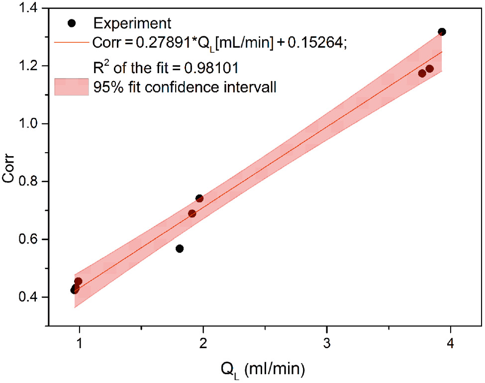
Correction factor depending on the incoming liquid volume flow rate.
In the second step of the evaluation, the integration of (9) is repeated for all cases applying the correction factors from the linear fit. FL and FG are determined by integration of (4) and (5). In conclusion, once the fit of the correction factor is determined for a given reactor geometry, the model can predict the trends of the stripping behavior for different operating parameters (e.g. temperatures, THF entrance concentrations, etc.). However, exact quantitative predictions will critically depend on the material parameters. Hence, for different material systems the model must be adapted.
Here, we further use the model to determine the number of transfer units of the microreactor. The number of transfer units (NTU) is defined by the expression
where yT|equil is calculated by means of a two-phase flash using Aspen Plus™. The results are shown in Figure 5.

Number of transfer units depending on the volume flow rate of nitrogen at incoming liquid flow rates of ca. 1 ml/min, 2 ml/min, and 4 ml/min and temperatures of 55°C, 60°C, and 65°C.
It can be stated that NTU is about 1 and increases slightly with the nitrogen volume flow rate. This demonstrates the capability and the potential for continuous downstream processing by solvent stripping, especially by scale up of the microstructured falling film device. An upscaled version has already experimentally been proven to be successfully implemented in gas/liquid reactions [40], [41], [42] and therefore the transfer to stripping with substantially higher throughput is to be expected.
5 Conclusions
In this work the STACK-1x-FFMR-LAB-V2 was investigated regarding its ability to continuously remove THF out of a THF-water-mixture. Therefore, mass transfer measurements were performed for nitrogen stripping at different reaction parameters [temperature (55°C, 60°C, 65°C), liquid (1, 2, 4 ml/min) and gas flow rate (200, 500, 650, 1000 ml/min)]. A complete elimination of THF did take place for liquid volume flow rates smaller than 2 ml/min and nitrogen volume flow rates larger than 400 ml/min at all three investigated temperatures (55°C, 60°C, and 65°C).
Additionally, a mass transfer model for description of the separation in the stripping process was established starting from the work of Moschou et al. [8], which dealt with the evaporation of a pure liquid.
The overall agreement of experiments and calculations within the tested parameter range (≤20%, for gas flow rates below 500 ml/min ≤11%) indicates that the model can be applied for the future prediction of operational parameter setting for THF stripping in STACK-1x-FFMR-LABV2 micro reactor. Therefore, this promising approach will help to eliminate THF very fast by the smallest necessary input of energy and stripping gas.
The ultimate goal would be the recovery not only of the stripping gas but also of the THF and water and thereby making the whole downstream processing greener (Figure 6).

This research was supported by the European Regional Development Fund EU grant EFRE Micro4Nano and Federal State of Rhineland-Palatinate.
About the authors

Sibylle von Bomhard studied biomedical chemistry at the Johannes Gutenberg University in Mainz, Germany and received her diploma in 2013. She moved to the Fraunhofer ICT-IMM, where she is currently finishing up her PhD thesis concerning the continuous formation of polymer-based nanoparticles with defined characteristics. In 2016 she was awarded a “Talentaspeed up” scholarship of the FraunhoferGesellschaft.

Karl-Peter Schelhaas studied physics at the Technical University in Darmstadt. He received his doctorate in experimental nuclear physics at the Johannes Gutenberg University, Mainz. In his postdoctoral research at the MPI for Chemistry, Mainz, he focused on nuclear photon scattering. After 15 years at Lurgi GmbH working on process development and plant design for energy and environmental technology he moved to the Fraunhofer ICT-IMM where he was working in the areas of process development and design of microstructural devices mainly for distributed and mobile energy systems.

Sabine Alebrand studied physics at the TU Kaiserslautern and finished her diploma in 2009. Afterwards, she started her PhD at the same university where her research focused on the so called “all-optical switching”, a topic of experimental solid state physics. After she finalized her PhD in 2013, she moved to Fraunhofer ICT-IMM (formely IMM GmbH), where today she works on the modelling of microfluidic systems. As a project leader she is further responsible for the development of various microfluidic analysis systems.

Anna Musyanovych studied biochemistry at the Lviv Polytechnic National University (Ukraine). She completed her PhD in 2003 under the supervision of Prof. H.-J. P. Adler at Technical University of Dresden (Germany). Her thesis was focused on the synthesis of amino-functionalized nanoparticles in the presence of surface-active initiators. In 2003 she moved to University of Ulm, working as a postdoctoral researcher in the group of Prof. K. Landfester. From 2009 to 2013, she was a project leader in Prof. K. Landfester’s group at Max Planck Institute for Polymer Research (Mainz), working on the development of multifunctional nanocolloids for bio-oriented applications. Currently she is working at Fraunhofer ICT-IMM. Her main research interests are in the areas of polymer-based particles with defined properties, biomaterials, encapsulation, and continuous flow technology.

Michael Maskos, graduate chemist, heads the Fraunhofer ICT-IMM as a director since 2014 in combination with a full professorship in the field of Chemical Process Engineering/Microfluidics at the Johannes Gutenberg University Mainz, Germany. Before that he was CEO of the former Institutfür Mikrotechnik Mainz GmbH (IMM). In 2000 he obtained the Research Award of the Boehringer-Ingelheim Foundation and in the same year went to McGill University in Montreal, Canada, as a research scholar of the German Academy of Natural Scientists Leopoldina. Back in Germany Maskos moved to Berlin where he took the lead of the Division Durability of Polymers at the Federal Institute of Materials Research and Testing (BAM). In 2015 Maskos won the Literature Prize of the Chemical Industry of Germany for the textbook “Polymers: Synthesis, Characteristics and Applications”.

Klaus S. Drese studied physics at the Julius Maximilian University in Wuerzburg and at the State University of New York at Stony Brook. He received his PhD in theoretical physics in the area of time-dependent quantum mechanics at the Phillips University in Marburg. He joined the simulation group of InstitutfürMikrotechnik Mainz GmbH (IMM) in 1998, became head of the Fluidics and Simulation Department in early 2004; since March 2007 he is the Scientific Director and is now heading the devison Analysis Systems and Sensors at the Fraunhofer ICT-IMM formaly IMM. The responsibilities of Dr. Drese cover the entire development work of micro- and bio-fluidic systems including simulation, silicon and thin film technology, laser material processing and optical sensors, mechanical micro machining as well as measuring technologies.
Acknowledgments
This research was supported by the European Regional Development Fund EU grant EFRE Micro4Nano and Federal State of Rhineland-Palatinate (Grant/Award number: Geschäfts-/Aktenzeichen 964-52207-4/47-9 81039695). The authors gratefully acknowledge Dr. Patrick Löb for providing the FFMR, Christian Hofmann for the technical assistance, and Martin Wichert’s help with ASPEN.
References
[1] Chasanis P, Lautenschleger A, Kenig EY. Chem. Eng. Sci. 2010, 65, 1125–1133.10.1016/j.ces.2009.09.067Search in Google Scholar
[2] Kane A, Monnier H, Tondeur D, Falk L. Chem. Eng. J. 2011, 167, 455–467.10.1016/j.cej.2010.09.090Search in Google Scholar
[3] Lam KF, Sorensen E, Gavriilidis A. Chem. Eng. Res. Design 2013, 91, 1941–1953.10.1016/j.cherd.2013.07.031Search in Google Scholar
[4] Thome JR. Int. J. Heat Fluid Flow 2004, 25, 128–139.10.1016/j.ijheatfluidflow.2003.11.005Search in Google Scholar
[5] Kandlikar SG. Heat Transfer Fluid Flow Minichannels Microchannels, 1st ed., Elsevier: Amsterdam, 2006.10.1016/B978-008044527-4/50003-7Search in Google Scholar
[6] Wenn DA, Shaw JEA, Mackenzie B. Lab Chip 2003, 3, 180–186.10.1039/b304494gSearch in Google Scholar PubMed
[7] Chambers RD, Spink RCH. Chem. Commun. 1999, 883–884.10.1039/a901473jSearch in Google Scholar
[8] Moschou P, Croon M de, van der Schaaf J, Schouten JC. Chem. Eng. Sci. 2012, 76, 216–223.10.1016/j.ces.2012.03.048Search in Google Scholar
[9] Yue J, Chen G, Yuan Q, Luo L, Gonthier Y. Chem. Eng. Sci. 2007, 62, 2096–2108.10.1016/j.ces.2006.12.057Search in Google Scholar
[10] Al-Rawashdeh M, Hessel V, Löb P, Mevissen K, Schönfeld F. Chem. Eng. Sci. 2008, 63, 5149–5159.10.1016/j.ces.2008.07.004Search in Google Scholar
[11] Aota A, Nonaka M, Hibara A, Kitamori T. Angew. Chem. 2007, 46, 878–880.10.1002/anie.200600122Search in Google Scholar
[12] Jähnisch K, Baerns M, Hessel V, Ehrfeld W, Haverkamp V, Löwe H, Wille C, Guber A. J. Fluorine Chem. 2000, 105, 117–128.10.1016/S0022-1139(00)00300-6Search in Google Scholar
[13] Ehrich H, Linke D, Morgenschweis K, Baerns M, Jähnisch K. CHIMIA 2002, 56, 647–653.10.2533/000942902777680063Search in Google Scholar
[14] Klemm E, Mathivanan G, Schwarz T, Schirrmeister S. Chem. Eng. Processing Process Intensification 2011, 50, 1010–1016.10.1016/j.cep.2011.05.020Search in Google Scholar
[15] Moschou P, Croon M de, van der Schaaf J, Schouten JC. Chem. Eng. Processing: Process Intensification 2013, 69, 95–103.10.1016/j.cep.2013.03.007Search in Google Scholar
[16] Yeong KK, Gavriilidis A, Zapf R, Hessel V. Catal. Today 2003, 81, 641–651.10.1016/S0920-5861(03)00162-7Search in Google Scholar
[17] Cypes SH, Engstrom JR. Chem. Eng. J. 2004, 101, 49–56.10.1016/j.cej.2003.10.014Search in Google Scholar
[18] Constantinou A, Ghiotto F, Lam KF, Gavriilidis A. Analyst 2014, 139, 266–272.10.1039/C3AN00963GSearch in Google Scholar PubMed
[19] Hessel V, Angeli P, Gavriilidis A, Löwe H. Ind. Eng. Chem. Res. 2005, 44, 9750–9769.10.1021/ie0503139Search in Google Scholar
[20] Angeli P, Gavriilidis A. Proc. Institut. Mech. l Eng. Part C J. Mech. Eng. Sci. 2008, 222, 737–751.10.1243/09544062JMES776Search in Google Scholar
[21] Wirth T (Ed.) Microreactors in Organic Synthesis and Catalysis, Wiley-VCH Verlag GmbH & Co. KGaA: Weinheim, Germany, 2008.Search in Google Scholar
[22] Hessel V, Hardt S, Löwe H. Chemical Micro Process Engineering, Wiley-VCH: Weinheim, 2005.10.1002/3527603581Search in Google Scholar
[23] Monnier H, Mhiri N, Falk L. Chem. Eng. Processing Process Intensification, 2010, 49, 953–957.10.1016/j.cep.2010.05.001Search in Google Scholar
[24] Hessel V, Ehrfeld W, Golbig K, Haverkamp V, Löwe H, Storz M, Wille C, Guber AE, Jähnisch K, Baerns M. In: Microreaction Technology: Industrial Prospects. Ehrfeld W, Ed., Springer Berlin Heidelberg: Berlin, Heidelberg, 2000, pp. 526–540.10.1007/978-3-642-59738-1_55Search in Google Scholar
[25] Ehrfeld W, Hessel V, Löwe H Microreactors: New Technology for Modern Chemistry. 1st ed., Wiley-VCH: Weinheim, 2000.10.1002/3527601953Search in Google Scholar
[26] Chasanis P, Kehrmann KM, Kern J, Zecirovic R, Grünewald M, Kenig EY. Chem. Eng. Processing Process Intensification 2011, 50, 1244–1251.10.1016/j.cep.2011.08.001Search in Google Scholar
[27] Sun X, Constantinou A, Gavriilidis A. Chem. Eng. Processing Process Intensification 2011, 50, 991–997.10.1016/j.cep.2011.06.004Search in Google Scholar
[28] Zanfir M, Sun X, Gavriilidis A. Ind. Eng. Chem. Res. 2008, 47, 8995–9005.10.1021/ie071653sSearch in Google Scholar
[29] In The Catalogue: Chemical Micro Process Technology Made by IMM. Institut für Mikrotechnik Mainz GmbH, Ed.: Mainz, 2009, pp. 64–67.Search in Google Scholar
[30] Hu F, Zhang Y, Du Y, Yuan H. Int. J. Pharma. 2008, 348, 146–152.10.1016/j.ijpharm.2007.07.025Search in Google Scholar
[31] Murakami H, Kobayashi M, Takeuchi H, Kawashima Y. Powder Technology 2000, 107, 137–143.10.1016/S0032-5910(99)00182-5Search in Google Scholar
[32] Mendoza-Munoz N, Quintanar-Guerrero D, Allemann E. DDF 2012, 6, 236–249.10.2174/187221112802652688Search in Google Scholar PubMed
[33] Betancourt T, Brown B, Brannon-Peppas L. Nanomedicine (London, England) 2007, 2, 219–232.10.2217/17435889.2.2.219Search in Google Scholar
[34] Bleul R, Thiermann R, Marten GU, House MJ, St Pierre TG, Häfeli UO, Maskos M. Nanoscale 2013, 5, 11385–11393.10.1039/c3nr02190dSearch in Google Scholar
[35] Kalliadasis S, Ruyer-Quil C, Scheid B, Velarde MG. Falling Liquid Films, Springer-Verlag London Limited: London, 2012.10.1007/978-1-84882-367-9Search in Google Scholar
[36] Wasden FK, Dukler AE. AIChE J 1990, 36, 1379–1390.10.1002/aic.690360911Search in Google Scholar
[37] Sobieszuk P, Pohorecki R, Cygański P, Kraut M, Olschewski F. Chem. Eng. J. 2010, 164, 10–15.10.1016/j.cej.2010.07.053Search in Google Scholar
[38] Dortmund Data Bank Software & Separation Technology GmbH. Vapor-Liquid Equilibrium Data of Tetrahydrofuran + Water. http://www.ddbst.com/en/EED/VLE/VLE%20Tetrahydrofuran%3BWater.php (accessed on 10.05.2016).Search in Google Scholar
[39] van Male P, Croon M de, Tiggelaar RM, van den Berg A, Schouten JC. Int. J. Heat Mass Transfer 2004, 47, 87–99.10.1016/S0017-9310(03)00401-0Search in Google Scholar
[40] Franke R, Jucys M, Löb P, Rehfinger A. Elements – Evonik Science Newsletter 2007, 20–24.Search in Google Scholar
[41] Löb P, Menges G, Hessel V. La Chimica L’Industria 2008, 132–138.Search in Google Scholar
[42] Vankayala BK, Löb P, Hessel V, Menges G, Hofmann C, Metzke D, Krtschil U, Kost H. Int. J. Chem. Reactor Eng. 2007, 5, 1–10.Search in Google Scholar
©2017 Walter de Gruyter GmbH, Berlin/Boston
This article is distributed under the terms of the Creative Commons Attribution Non-Commercial License, which permits unrestricted non-commercial use, distribution, and reproduction in any medium, provided the original work is properly cited.
Articles in the same Issue
- Frontmatter
- In this issue
- Original articles
- Two-step hydrogen transfer catalysis conversion of lignin to valuable small molecular compounds
- An efficient and catalyst-free synthesis of N-arylidene-2-arylimidazo[1,2-a]pyridine-3-ylamine derivatives via Strecker reaction under controlled microwave heating
- Synthesis of 1,4-dihydropyrimidines with immobilized urease: effect of method immobilization on magnetic supports
- Water-soluble heteropolyacid-based ionic liquids as effective catalysts for oxidation of benzyl alcohol in water with hydrogen peroxide
- Fe-carbon nanoreactors obtained from molasses as efficient catalysts for limonene oxidation
- Selective solvent evaporation from binary mixtures of water and tetrahydrofuran using a falling film microreactor
- The continuous synthesis of Pd supported on Fe3O4 nanoparticles: a highly effective and magnetic catalyst for CO oxidation
- Oxidative polymerization of waste cooking oil with air under hydrodynamic cavitation
- Bio-based polymer from heterogeneous catalytic polymerization of vegetable oils
- Intensification of β-glucosidase enzyme production from Aspergillus niger using extractive fermentation with an aqueous two-phase system
- Book review
- Sustainable green chemistry