A Low Conversion Loss Eighth Harmonic Mixer with Wide Band-Stop Filters for Low Cost 94 GHz Receiver Front-Ends
-
 ,
,

Abstract
A 75–110 GHz low conversion loss (CL) eighth harmonic mixer is realized for low cost 94 GHz receiver front-ends. The mixing diodes are realized by GaAs foundry of Nanjing Electronic Devices Institute (NEDI) and its 3-D model is analyzed for impedance calculation of RF, LO, IF port. Wide band-stop filters and phase shift networks for RF and idle frequency signals recycling are designed with optimum load impedance for low CL. The measured CL of the mixers is lower than 28 dB, 18 dB, 16.5 dB in 75–110 GHz, 87–104 GHz and 90–100 GHz, respectively. The lowest tested CL is 14.7 dB at 94 GHz. The mixers are successfully applied in miniature and low cost 94 GHz receiver systems.
1 Introduction
Millimeter-wave mixers are widely used in the field of radar, communications, satellite remote sensing and so on. There are two kinds of mixers, such as fundamental mixers and harmonic mixers, Comparing with fundamental mixers, the biggest advantage of harmonic mixers is low frequency of LO which is particularly difficult to achieve in millimeter-wave. The defect of harmonic mixer is high CL. Therefore, broadband, high-order and low CL harmonic mixers remain to be a technical problem, there are still many research papers on it [1]–[14]. Due to the high CL of the high-order harmonic mixers, their main application is restricted in field of millimeter-wave test instruments such as vector network analyzer and spectrum analyzers.
To solve high CL of the eighth harmonic mixer, wide band-stop filters with radial stubs and phase shift microstrip lines are designed and combined for RF and idle frequency signals recycling. A novel compact micrstrip resonant cell (CMRC) IF low pass filter (LPF) is adopted for extraction of IF signals and rejection LO and unneeded signals. LO band pass filter (BPF) with parallel coupled lines is designed for suppression of IF signals. The designed harmonic mixers achieved low CL of 16.5 dB in 90–100 GHz. By combing with high gain and low noise amplifier (LNA), we can develop miniature, low power consumption and low cost 94 GHz receivers.
2 Circuit design
2.1 The eighth harmonic mixer
The mixer circuit layout is given in Figure 1. It consists of following parts, anti-parallel mixing diode, RF waveguide-finline-microstrip transition, RF matching networks, RF and idle frequency recycling reflector networks, IF LPF and LO BPF. First, the different parts of the circuit are optimized, such as LO BPF, IF CMRC LPF, and RF and idle frequency recycling network, respectively. Then, the different parts are combined with physical structure of the diode for whole circuit simulation, and its multi-port S-parameter file is extracted and combined with the diode SPICE mode for CL analysis. We optimized the matching circuit until the performance of the mixer meets the requirements.

Circuit layout of the eighth harmonic mixer.
2.2 The mixing diode
The anti-parallel mixing diode presented in Figure 2 is realized by GaAs foundry of NEDI. The main diode SPICE model parameters are listed as follows [15]: Rs=6.4 Ω, Cjo=7.7 fF, n=1.4, Is=1.03e–12A, Vf=0.525 V (1 µA), Vbr=4.625 V (10 µA). The diode main physical parameters are presented as follows, anode and cathode pad area 0.06 × 0.06 mm2, air bridge length 0.03 mm, Schottky contact area 5 µm2. The diode uses Ti/Mo/Au multilayer metal system, wherein the Au layer is used as the bonding metal, and Ti as a barrier metal. Due to the high operating frequency, parasitic parameters of the diodes would have a great impact on circuit performance. Electromagnetic simulation software is applied for extracting the diode S-parameters, and the diode material settings are same as those in Table 1. By combing with its SPICE model, harmonic balance analysis (HBA) is used for RF, LO, IF port impedance discussing.
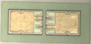
Diode picture.
Diode material setting.
| Material | Doping | Thickness (µm) | Setting |
| N+ GaAs epitaxial | 2×10¹⁷ | 0.2 | Perfect conductor |
| N GaAs buffer layer (εr=12.9) | 5×10¹⁸ | 4 | Lossless dielectrics |
| GaAs substrate (εr=12.9) | 0 | 50 | |
| SiO2 layer (εr= 4) | 0 | 0.1 |
2.3 The IF LPF circuit
The novel CMRC IF LPF circuit is given in Figure 3, and its equivalent circuit is presented in Figure 4. Circuit substrate is RT/duroid5880 with dielectric constant of 2.22, and thickness of 0.127 mm. It can be found in Figure 5 that the simulated 3 dB cutoff frequency is around 1.7 GHz, and the suppression of LO signals is higher than 35 dB in 9–14 GHz, guaranteed a high LO-IF port isolation.

Circuit layout of IF LPF.

Equivalent circuit of IF LPF.

Simulated S-parameters of IF LPF.
2.4 The LO BPF circuit
The LO BPF is parallel coupled lines structure, its circuit test setup is shown in Figure 6, which consists of five resonators, and each resonator is about half of one wavelength of the operating frequency. Circuit board is ceramic dielectric with thick of 0.254 mm and dielectric constant is 9.6. The tested results are presented in Figure 7, IL is less than 2 dB, return loss is greater than 15 dB, and suppression of 0–1.5 GHz IF signals is greater than 50 dB.

Test setup of LO BPF.

Measured S-parameters of the LO BPF.
2.5 The mixer circuit analysis
Commonly, millimeter wave eighth harmonic mixer CL is high. Therefore, wide band-stop filters with radial stubs and phase shift microstrip lines are designed and combined for recycling of RF and idle frequency signals. When the RF signals are transmitted to the diode, their leakage to LO and IF common port must be taken into consideration for recycling, then are 2ωP±ωs, 4ωP±ωs frequency signals. As presented in Figure 8, at the right end of the diode, a butterfly radial stub with radius of r1 is applied to present short circuit to RF signals (75–110 GHz) at center frequency of 90 GHz. The other radial lines r2, r3, r4, r5, combined with phase shift lines L1 and L2, are designed to present short circuit at 147.5 GHz and 139 GHz (about center frequency of 2ωP+ωs and 4ωP+ωs signals), 50 GHz and 42.5 GHz (about center frequency of ωs – 2ωP and ωs – 4ωP signals), respectively. Simulated reflection phase angle of the circuit is given in Figure 9. The reflection angle shows that the deviation from 180° is less than 15 degrees, and the short circuit effect is perfect to idle frequency signals in 40–150 GHz. The simulated results in Figure 10 show that the attenuation in 40–150 GHz is greater than 15 dB. For harmonic mixing products such as 6ωP ± ωs (131–192 GHz and 19–27 GHz), and 8ωP + ωs (150–220 GHz) frequency signals, recycling are omitted because that the energy can be reused is very limited.

Recycling circuit layout.

Reflection phase angle of recycling circuit.

Simulated S-parameters of recycling circuit.
3 Implementation and measurements
3.1 Implementation
The RG5880 circuit substrate and the mixing diode are mounted to block with 220°C and 150°C solder, respectively. The LO BPF is mounted to block with silver epoxy H20E. IF and LO interface connector are SMA-KFD45, and RF interface is standard WR-10 waveguides. The mixer block is aluminium and gold-plated, and its photo is presented in Figure 11.

Photo of the mixer.
3.2 Measurements
The RF signals are generated by Agilent U85104A and attenuated to –10 dBm by Mi-Wave 510W. The LO signals are provided by Agilent 8257D, and down-converted IF signals are monitored by Agilent E4440A spectrum analyzer. The output IF is fixed at 1 GHz and LO signals’ pumping power is set at 18 dBm. It can be found in Figure 12 that the tested CL is less than 28 dB, 18 dB, 16.5 dB in 75–110 GHz, 87–104 GHz, 90–100 GHz, respectively. The minimum CL is 14.7 dB at 94 GHz. The plot of the two mixers’ CL deviation is lower than 3 dB, which shows good conformity. Figure 13 shows that the tested typical suppression of IF harmonics such as second, third, and fourth is 45 dBc, 40 dBc, 60 dBc respectively. As described in Figure 14, the measured LO-IF port isolation is better than 35 dB. Table 2 demonstrates that the CL of the designed mixer is much lower than Millitech, HXI, Farran’s commercial products, and reached RPG’s performance level.

Measured CL of mixer.

IF Harmonics suppression.

Measured LO-IF port isolation.
4 94 GHz receiver front-ends
Two 94 GHz receiver front-end with different mixer types are designed as in Figure 15. For conventional receiver with fundamental mixer, LO signal is realized by a complex multiply chain (Ka-band active tripler, Ka-band BPF, Ka-band drive amplifier, W-band diode tripler, W-band BPF, W-band drive amplifier). It can be found in Table 3 that their noise figure is same. The gain of the receiver with eighth harmonic mixer is low about 6.5 dB because of its high CL, and its gain can be easily compensated by IF amplifier. The receiver volume, power consumption of this work is low and it is simple and easy to realize. The receiver is composed by LNA and mixer block, it can be further minimized if the LNA MMIC chip is integrated with harmonic mixer circuit. The selling price of the conventional receiver is one hundred and fifty thousand Yuan, and the receiver in this work is fifty thousand Yuan, it’s very attractive for low cost 94 GHz receivers.

The 94 GHz receiver front-ends. (a) Receiver with eighth harmonic mixer, (b) conventional receiver with fundamental mixer.
94 GHz receiver front-ends.
| 94 GHz receiver | RF (GHz) | Dimension (mm3) | Power consumption (W) | Gain (dB) | Noise figure (dB) |
| This work | 93–95 | 80×38×20 | 0.15 | 11.5–13 | 2.5–3.1 |
| Conventional | 110×30×20 | 3.5 | 18–19.4 | 2.5–3.1 |
5 Conclusion
Hybrid integrated 75–110 GHz low CL eighth harmonic mixer is achieved. RF and idle frequency signals are recycled by wide band-stop filters for low CL. A novel CMRC IF LPF is adopted for extraction of IF signals and its suppressing to LO signal is high. The measured CL is less than 28 dB in 75–110 GHz, less than 18 dB in 87–104 GHz, and less than 16.5 dB in 90–100 GHz. Because of its low CL, it can be widely applied in miniature, low cost, and low power consumption 94 GHz receiver systems.
References
[1] http://www.millitech.com.Search in Google Scholar
[2] http://www. hxi.com.Search in Google Scholar
[3] http://www.farran.com.Search in Google Scholar
[4] http://www.radiometer-physics.de.Search in Google Scholar
[5] R. Kawasaki and M. Akaike, “A broad-band second-harmonic mixer covering 76-106GHz,” IEEE Trans. Microw. Theory Tech., vol. 26, pp. 425–427, June 1978.10.1109/TMTT.1978.1129406Search in Google Scholar
[6] M. Asher, “A novel general approach for the optimum design of microwave and millimeter wave subharmonic mixers,” IEEE Trans. Microw. Theory Tech., vol. 44, pp. 1997–2000, Nov. 1996.10.1109/22.543954Search in Google Scholar
[7] S. Raman, F. Rucky, and G. M. Rebeiz, “A high-performance W-band uniplanar subharmonic mixer,” IEEE Trans. Microw. Theory Tech., vol. 45, pp. 955–962, June 1996.10.1109/22.588609Search in Google Scholar
[8] M. W. Chapman and S. Raman, “A 60GHz uniplanar MMIC 4×subharmonic mixer,” IEEE Trans. Microw. Theory Tech., vol. 50, pp. 2580–2588, Nov. 2002.10.1109/TMTT.2002.804638Search in Google Scholar
[9] Q. Xue, K. M. Shum, and C. H. Chan, “Low conversion-loss fourth subharmonic mixers incorporating CMRC for millimeter-wave applications,” IEEE Trans. Microw. Theory Tech., vol. 51, pp. 1449–1454, May 2003.10.1109/TMTT.2003.810153Search in Google Scholar
[10] T. Y. Yun, Q. Xue, and C. H. Chan, “Novel subharmonically pumped mixer incorporating dual-band stub and in-line SCMRC,” IEEE Trans. Microw. Theory Tech., vol. 51, pp. 2538–2547, Dec. 2003.10.1109/TMTT.2003.820152Search in Google Scholar
[11] Z. Y. Liu and R. M. Weikel, “High-order subharmonically pumped mixers using phased local oscillators,” IEEE Trans. Microw. Theory Tech., vol. 54, pp. 2977–2982, July 2003.Search in Google Scholar
[12] M. S. Kang, B. S. Kim, K. W. S. Kim, and W. J. Byun, “80-100GHz sub-harmonically and fourth-harmonically pumped diode mixers using 0.lµm GaAs pHEMT process,” in 37th International Conference on Infrared, Millimeter, and Terahertz Waves, Wollongong, NSW, Australia, pp. 1–2, Sept. 2012.10.1109/IRMMW-THz.2012.6380316Search in Google Scholar
[13] T. Bryllert, V. Drakinskiy, K. B. Cooper, and J. Stake, “Integrated 200–240GHz FMCW radar transceiver module,” IEEE Trans. Microw. Theory Tech., vol. 61, pp. 3808–3815, Oct. 2013.10.1109/TMTT.2013.2279359Search in Google Scholar
[14] D. Z. Ding and J. P. Xu, “Low conversion loss full E-band seventh-harmonic mixer with compact filter,” Electron. Lett., vol. 50, no. 7, pp. 526–528, March 2014.10.1049/el.2014.0028Search in Google Scholar
[15] C. F. Yao, M. Zhou, G. Lin, C. H. Xu, Y. N. Kou, G. Wu, and J. C. Wang, “Development of D-Band and G-Band frequency multiply sources with Schottky diodes of NEDI,” J. Infrared Millimeter Waves, vol. 33, no. 3, pp. 256–262, June 2014.Search in Google Scholar
©2016 by De Gruyter
Articles in the same Issue
- Frontmatter
- Improved Cross Polarization and Broad Impedance Bandwidth from Simple Single Element Shorted Rectangular Microstrip Patch: Theory and Experiment
- Compact Bandpass Filter Based on Parallel-coupled Lines and Quasi-lumped Structure
- Compact Dual-Band Bandpass Filter Using Stubs Loaded Ring Resonator
- A Low Conversion Loss Eighth Harmonic Mixer with Wide Band-Stop Filters for Low Cost 94 GHz Receiver Front-Ends
- Design of a Compact Quad-Channel Diplexer
- A Low Phase Noise Fully Monolithic 6 GHz Differential Coupled NMOS LC-VCO
- The Interaction of Terahertz Waves and a Dusty Plasma Slab with Epstein Distribution
- Statistical Beamforming for Interference Mitigation in Multi-cell Massive MIMO Systems
- Interference Mitigation Based on Intelligent Location Selection in a Canonical Communication Network
- A Novel Iteration Model for Electromagnetic Scattering from Rough Surfaces
- A Novel Approach to Photonic Generation and Modulation of Ultra-Wideband Pulses