
Ultralight sponges of poly(para-xylylene) by template-assisted chemical vapour deposition
-
Tobias Moss


Abstract:
Particle foams and open cell sponges play nowadays an important role in academia and industrial research. The fabrication of new high-performance foams is one of the challenges. Until now, it is impossible to visualise the quality of particle foams, and the quantification is only possible with expensive analytical methods like scanning electron microscopy. In this work, we demonstrate a simple method for the visualisation of void sizes and defects inside particle foams on the basis of expanded polystyrene. The concept was transferred to porous materials, which work as templates for the formation of ultralight poly(para-xylylene) foams with stunning properties.
1 Introduction
Polymer foams are widely used in everyday life because of their excellent properties like low weight, good weight/strength ratio and extraordinary thermal and acoustic insulation. A wide range of different foams are available that are classified as open cell or closed cell foams. In melamine formaldehyde foam, an open cell foam, the structure consists of cell struts only without any walls. Open cellular foams are mostly used for acoustic insulation and cushioning. By contrast, closed cell foams like expanded polystyrene (EPS) are generally more rigid and are in use for packaging applications and thermal insulation (1). EPS is a bead foam that consists of small foamed beads that are fused together with hot steam. EPS has a unique structure in different length scales (2). During the formation of EPS, various parameters have an influence on the resulting material. For example, the cell size can be controlled by the expansion time and temperature as well as nucleating agents (3) or low molecular weight components as reported by Stafford et al. (4). The morphology of the foam is highly important for the final properties. Also, the fusion quality has a high impact on the materials properties like tensile strength (5) and fracture toughness (6). Besides the macrovoids, the interstitial volume in the areas where three or more beads gather are important. They can appear as defects that initialise cracks and lead to faster crack propagation. Here, two modes of failure are possible. Badly fused foams mainly fail in interbead mode along the bead-bead interfaces, whereas well-moulded foams fail in intrabead mode. Here, cracks run through the beads because the fused interface is stronger than the rupture strength of the beads.
The correlation of welding quality and mechanical properties was shown in previous studies (5), (6), (7) where the fusion quality was determined using the degree of fusion (DOF). This is defined as the ratio of areas of intra- and interbead fracture. However, the DOF does not necessarily give information about the mechanical properties of a material. With a high DOF, good mechanical properties can be expected, whereas a low DOF does not allow any statement concerning the mechanical properties. Although the DOF has some drawbacks, it is an extremely important parameter to assess the fusion quality and cannot be neglected. To the best of our knowledge, only one method that requires mechanical testing, scanning electron microscopy (SEM) analysis of the fracture surface and evaluation of the failure mode is known and used to determine the DOF (5), (6), (7). This method is useful but has limitations and drawbacks, such as the high efforts and costs. An alternative to this method could be the chemical vapour deposition (CVD) coating by poly(para-xylylene) (PPX).
The preparation of PPX by pyrolysis of p-xylene and subsequent CVD was first reported by Szwarc in 1947 (8). It was a yellowish cross-linked material. The preparation of linear PPX (trade name Parylene) by pyrolysis of [2.2]paracyclophane and followed by CVD polymerisation of 1,4-quinodimethane (Scheme 1) reported by Gorham in 1966 marked the breakthrough for the technical application of PPX (9). Nowadays, PPX is mainly used as highly efficient packaging material for demanding medical or electronic applications (10), (11) because of its biostability and biocompatibility as well as its superior electrical insulation and barrier properties in combination with very good thermal and hydrolytic stability as well as excellent solvent resistance (12). The big advantage of the polymerisation out of the gaseous phase is the homogeneous and conformal coating of complex structures like microdevices (13), nanotrenches (14) or fibre mats (15), (16). In addition, sensitive substrates are suitable for the PPX coating because the polymerisation proceeds at room temperature.
![Scheme 1: Reaction scheme of the CVD of [2.2]paracyclophane to PPX.](/document/doi/10.1515/epoly-2016-0329/asset/graphic/j_epoly-2016-0329_scheme_001.jpg)
Reaction scheme of the CVD of [2.2]paracyclophane to PPX.
The aim of this study was to use porous structures as sacrificial templates for porous 3D PPX structures. Simultaneously, we wanted to evaluate the CVD coating of PPX of porous sponges as a novel analytical tool for the visualisation of the void structures of porous 3D objects like EPS foams and sugar cubes, which would help to understand structure-property relationships.
2 Experimental section
2.1 Materials
[2.2]Paracyclophane (Specialty Coating Systems, Indianapolis, IN, USA), chloroform p.a. (Sigma Aldrich, Munich, Germany), Disperse Red 1 (Sigma Aldrich) and sugar cubes were used as received (Südzucker, Mannheim, Germany). Tetrahydrofuran (THF, technical grade, CSC Jäklechemie, Nürnberg, Germany) was distilled before use. Expanded polystyrene were obtained from Neue Materialien Bayreuth (Bayreuth, Germany) with densities of 25 and 40 g/l, respectively. For each density, the moulding conditions (steam temperature and steaming time) were adjusted to achieve samples with low and high fusion quality.
2.2 Methods
The PPX coating thickness was determined by measurement of the step height with a Veeco Dektak 150 Profilometer. Therefore, a glass slide was coated simultaneously with the samples. The deposited PPX layer on the glass slide was cut at three different positions, and the step height was measured with a profilometer. The average height of the three measurements gave the coating thickness. The successful coating of the templates was proven by infrared (IR) spectroscopy. This was done with a Digilab IR spectrometer of the Excalibur series equipped with an ATR unit consisting of a ZnSe crystal. SEM (Zeiss Leo 1530) was used to characterise the morphology of the samples. Before the measurements, these were sputtered with 2 nm platinum. Microcomputed tomography was done with a Bruker Skyscan microtomograph 1072. Scan parameters were 29 kV, 172 μA, 60× and 180° rotation with 0.23° angular steps. The images were evaluated with the software MAVI (version 14.1).
Contact angles were determined on a Krüss Drop Shape Analyzer Model DSA 25S (Advance Drop Shape Version 1.3.1.0). For each measurement, a 5-μl water drop was settled on the surface and five values were taken with a Young Laplace fit. Ten drops were analysed for every sample to give the static contact angle. Thermal conductivity was determined on a Hot Disk TPS 2500 S equipped with Kapton insulated C5465 Sensor (radius 3.189 mm). An external PT100 Sensor was measuring the surrounding temperature, and a method for bulk materials was used with a measurement time of 10 s and a heating power of 5 mW. The obtained data were evaluated with the software Hot Disk Thermal Analyzer Version 7.2.8. The samples had a size of 16×16×11 mm.
2.3 PPX coating and template removal
The procedure for generating the inverse structure of a porous material is shown in Scheme 2 and included the PPX coating and removal of the template. The PPX coatings were done in an SCS Labcoter® 1 PDS 2010. The EPS samples were cut in pieces of 20×20×12 mm, and prior to use, all samples were dried over night at 50°C and reduced pressure. The EPS samples were placed in the deposition chamber by impaling them on a bed of nails located on the rotating sample holder to ensure a uniform coating from all sides. The sugar cubes were placed directly on the rotating table of the Coater. The thickness of the PPX coating was controlled by the amount of paracyclophane. The paracyclophane was vaporised at 150°C and then pyrolysed at 650°C under reduced pressure. The deposition chamber was kept at a pressure below 50 mbar at room temperature. Coatings with thicknesses of 0.75, 1.5 and 2.0 μm were obtained.
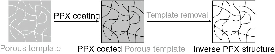
Schematic diagram for the fabrication of a PPX sponge using porous templates.
First, a porous material was coated with PPX by the CVD approach so that it filled the empty space inside the template. Afterwards, the template was removed by dissolving it, and the resulting PPX sponge showed the inverse structure of the porous template.
Each PPX-coated EPS sample was extracted with 50 ml THF under stirring for 48 h. The solvent was changed during the extraction process several times, and afterwards the samples were dried at 50°C under reduced pressure.
The PPX-coated sugar samples were extracted for 72 h under stirring with deionised water at 60°C. The water was changed at various times during the extraction process. Afterwards, the samples were dried at 50°C under reduced pressure.
3 Results and discussion
3.1 PPX-coated EPS samples
The EPS samples were coated with different coating thickness of PPX by CVD. The deposition chamber had to be evacuated for 3 h because of the high amount of gas that had to diffuse out of the EPS samples until the working pressure was reached. After the coating was completed, the pressure inside the coating device was allowed to increase slowly in order to avoid collapse of the samples. The presence of the PPX coatings was verified by comparison of IR spectra of pure EPS, PPX-coated EPS, and pure PPX (Figure 1A). The spectra of the pure EPS sample showed the characteristic absorbance bands for monosubstituted benzene rings at 694 and 754 cm−1, which are characteristic of polystyrene. The PPX spectrum shows a band at 820 cm−1, which is typical for para-disubstituted benzene rings. The spectrum of the PPX-coated EPS sample has all three bands and proves the successful PPX coating on the EPS sample. Figure 1B includes the IR spectra of three different PPX coating thicknesses, and only the area of interest between 600 and 1600 cm−1 is shown. The comparison of the three different coating thicknesses nicely illustrates the growth of the PPX band at 820 cm−1 with increasing coating thickness, and a simultaneous decrease of the two characteristic bands for monosubstituted benzene rings. In order to prove that the inside of EPS samples was also coated with PPX, the samples were cut, and IR spectra of the inside were recorded (Figure 1C and D). The difference between spectra C and D is the density of the used EPS. The density of the EPS out of spectrum C was lower (25 g/l) and from spectrum D was higher (40 g/l). In both spectra, the characteristic bands for the PPX and polystyrene are visible, and on the outer surface, the PPX band is significantly stronger than inside the samples. A comparison of the spectra from the inside of the samples shows clearly that the PPX band in the low-density EPS is stronger than that in the high-density EPS. This observation indicates that the density of the EPS has an impact on the diffusion of the reactive moiety into the samples. Therefore, the applied coating technique is suitable for the desired purpose as an optical illustrator of welding qualities in particle foams.
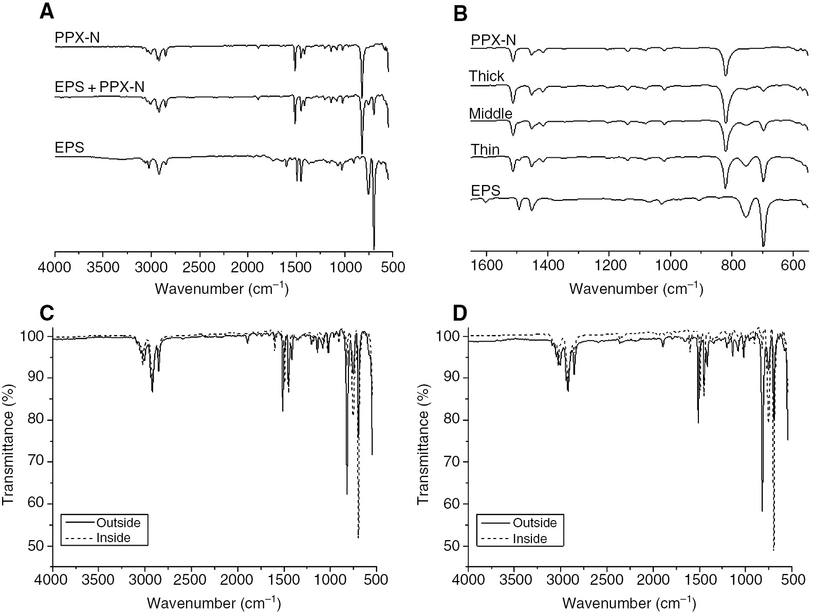
The IR spectroscopy confirmed the successful PPX coating of EPS from the outside as well from the inside.
IR spectra of EPS, coated EPS samples and PPX (A, B). Comparison of IR spectra of the outer surface and inside of the samples for the EPS with a density of 25 g/l (C) and 40 g/l (D).
SEM images of the uncoated (A, C) and PPX-coated EPS (B, D) are shown in Figure 2. The macroscopic structure of the EPS was not damaged through the PPX coating (Figure 2B). The comparison of Figure 2C and D presents the additional polymer layer on the bead walls, which was obtained by the PPX coating. These images indicate the good diffusion of PPX also inside the foam.
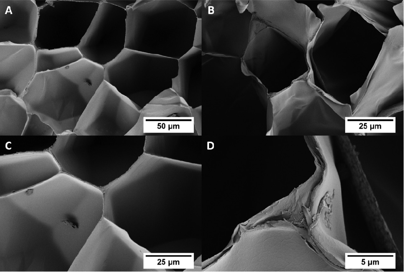
SEM images of the EPS before (A, C) and after (B, D) the PPX coating.
The IR spectra and SEM images proved the coating of the EPS with PPX from the inside and outside so that the polystyrene could be extracted by placing the sample in THF, which was stirred to achieve a higher diffusion as a result of the motion inside the solvent. After the polystyrene extraction, the remaining PPX formed a stable cube with the same dimensions like the EPS templates (Figure 3A). Depending on the welding quality and density of the EPS, the resulting PPX structure showed different frameworks (Figure 3B). The monomer gas could better penetrate into the bad welded EPS so that the PPX was formed in the existing voids of the foam and makes these voids visible (Figure 4A and C). By contrast, the PPX sponges out of the well welded EPS were inside nearly PPX free (Figure 4B and D). Also, the density had an impact on the penetration of the monomer gas into the EPS as already proven by IR spectroscopy. The comparison of Figure 4B and D shows clearly that more monomer gas could penetrate into the lower-density EPS (B) than into the higher-density EPS (D).
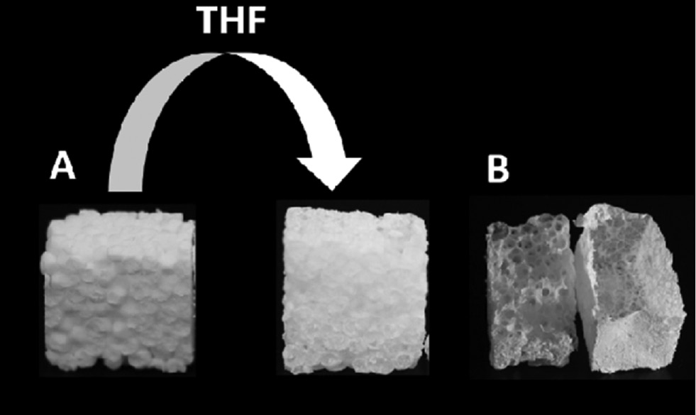
Scheme of the extraction of polystyrene to form a PPX cube (A) and photo of the inverse PPX structure of a bad (left) and good (right) welded EPS (B).
The PPX shows nicely the voids of the bad welded EPS, whereas the PPX structure of the good welded EPS is nearly hollow.
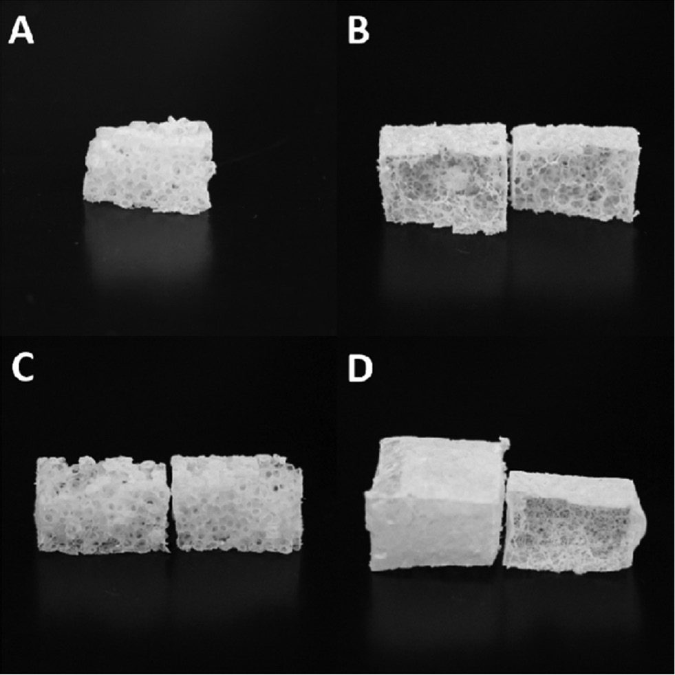
Photos of the resulting PPX structures after the extraction of polystyrene for the EPS template with a density of 25 g/l (A, B) and 40 g/l (C, D) and a bad (A, C) and good (B, D) welding quality.
It was shown that the 1,4-quinodimethane gas could penetrate porous structures like EPS and polymerise inside these structures to build the inverse structure. This technique allows the visualisation of defects and voids in particle foams and also allows a qualitative statement concerning the welding quality and density.
3.2 Sugar cubes as template for PPX foams
The experiments with the EPS showed that the monomer gas can penetrate into porous structures to build the inverse structure. To prove that this concept can be adapted onto any porous structure, sugar cubes were coated with PPX with the same three thicknesses like the EPS samples and the sugar was afterwards removed by extraction with hot water for several days (Figure 5A). For all three PPX thicknesses, stable PPX foams could be obtained, and the cross section of the resulting foams showed that the monomer penetrates the whole structure (Figure 5B). Coatings with PPX thickness of 0.50 μm did not result in stable foams. Obviously, the amount of PPX was too low to form a stable sponge. This can be explained by the decreasing coating thickness with increasing distance into small channels (17). Depending on the coating thickness, foams with an apparent density between 7 and 20 g/l and porosities over 98% were received (Table 1). These values are in the area of new discovered, ultralight sponges made out of electrospun short cut fibres with densities between 3 and 9 g/l and a porosity of 99.6% (18). Images made with microcomputed tomography (μCT) proved the continuous foam formation also inside the structure (Figure 5C and D). The cross-sectional analysis gave a good impression of the tangled structure of the PPX foam. Thus, PPX coating of porous structures is also a straightforward method for producing ultralight foams.
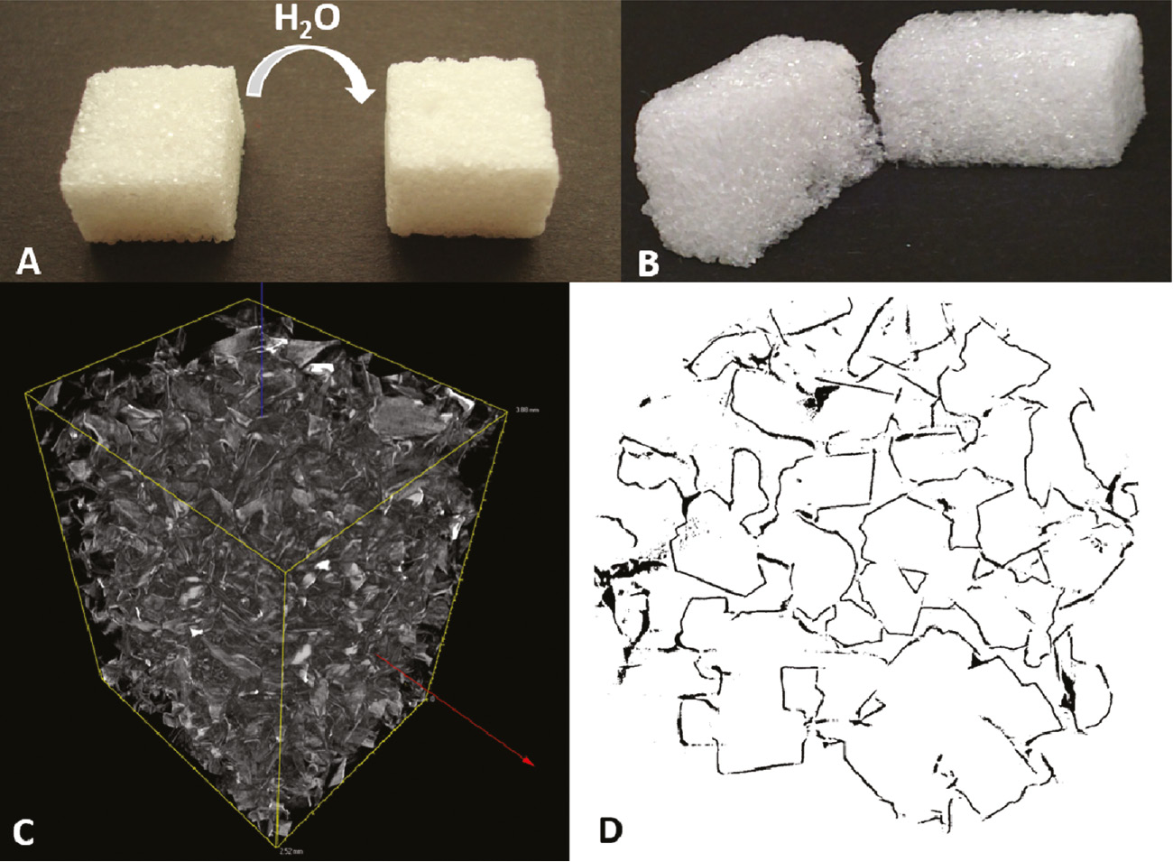
Sugar cubes served as templates for the PPX foam formation and μ-CT analysis confirmed the continous PPX scaffold.
A PPX-coated sugar cube was extracted with hot water to form a PPX foam (A). The cross section of the PPX foams shows the complete penetration of the gas into the inside (B). μ-CT was used for imaging the 3D structure of the foam (C) and cross-sectional analysis (D).
Summary of the properties of the three different produced PPX foams.
| Sample | PPX thickness (µm) | Apparent density (g/l) | Porosity (%) | Thermal conductivity (mW/m·K) | Thermal diffusivity (mm2/s) |
|---|---|---|---|---|---|
| Foam 1 | 0.75 | 7.27 | 99.3 | 21.98 | 1.03 |
| Foam 2 | 1.50 | 13.44 | 98.8 | 26.36 | 1.01 |
| Foam 3 | 2.00 | 19.47 | 98.2 | 27.33 | 0.80 |
The rectangular sugar crystals were coated with PPX, and after the removal of the sugar, PPX shells with a rectangular shape were obtained, which can be seen in the SEM images in Figure 6A and B.
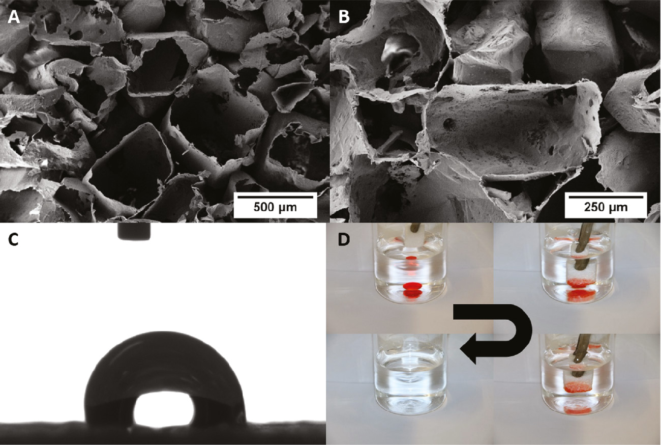
SEM images of the PPX foam (A, B) after the extraction of the sugar shows nicely the remained PPX structure and the shape of the originally sugar crystals, which were coated by the PPX. Water drop on PPX foam (C). Photos of the separation quality of the PPX foam (D). A drop of dyed chloroform (dye: Disperse Red 1) was put into a beaker with water. The foam was submerged into the water and absorbed selectively the chloroform.
Duan et al. (19) showed that ultralight PPX-coated foams exhibit superhydrophobic behaviour. The requirements for superhydrophobic behaviour are given for the PPX foams, but in Figure 6C, a water drop on the PPX foam is shown, and it is clearly observable that no superhydrophobic behaviour is existent (contact angle 112°±8°). An explanation could be that the air pockets under the water drop are too big so that the water penetrates partially into the foam and a metastable state between the Cassie-Baxter and the Wenzel states is formed. To get superhydrophobicity, the drop has to be in the Cassie-Baxter state. Although no superhydrophobicity is existing, the foam can be used to separate hydrophilic and hydrophobic liquids. A dyed drop chloroform was placed into a beaker filled with water (Figure 6D). The PPX foam was then dunked into the water, which was not absorbed into the foam. When the foam touched the chloroform, this was absorbed instantly into the foam. The PPX foam can therefore be used to separate hydrophobic and hydrophilic liquids selectively. Because of the good thermal stability and solvent stability even at higher temperatures of PPX, these foams could be used for oil-water separation inside engines.
Foams are used for insulation applications, e.g. thermal or noise insulation like melamine foams (20). Measurements of the thermal properties were done with a hot disk. The thermal conductivity was measured to be below 28 mW/m·K, and the thermal diffusivity was determined between 0.80 and 1.03 mm2/s (Table 1). Comparison of the thermal conductivity with existing foams is shown in Table 2. The values of the PPX foam are in the same range like the existing insulating materials and can compete with these materials exploiting the advantage of PPX like solvent and hydrolytic resistance in combination with excellent biocompatibility.
Summary of thermal conductivity of existing foams in comparison with the novel PPX foams.
| Material | Thermal conductivity (W/m·K) | Density (g/l) | References |
|---|---|---|---|
| PPX | 0.022–0.027 | 7–20 | This study |
| EPS | 0.035–0.042 | 10–40 | (10), (21) |
| Polyurethane foam | 0.020–0.024 0.028 | 20–50 104 | (22) (23) |
| Melamine formaldehyde foam | <0.035 | 9 | (20) |
4 Conclusions
The low specific weight of foams make them an interesting material for a lot of applications, but the development of novel foams and the in-depth characterisation are important to improve their properties. Here we show that macroscopic and complex porous structures can be replicated with PPX. Because of the conformal coating via CVD, the PPX replicate structures are a powerful tool for the determination of the quality of EPS foams. The ability of the monomer gas to penetrate into the foam and to pattern the inverse structure makes it possible to visualise defects and void sizes. The concept of porous material as template was then transferred, and novel, ultralight PPX foams could be produced with a cheap, easy accessible template material using sugar cubes. These foams showed interesting thermal properties and wetting behaviour that could be used in insulation applications or in the oil/water separation even at higher temperatures because of the excellent stability of PPX. The particular potential of this approach is that the numerous PPX derivatives could be coated by CVD on foam or sugar templates (24) or modified after deposition (25), which allow a large variety of new foam structures.
Acknowledgements
The authors would like to thank Specialty Coating Systems for supplying of [2.2]paracyclophane (DPX), the University of Bayreuth and TransMIT GmbH for financial support and Matthias F. Burgard for help with SEM analysis.
References
1. Brody AL, Marsh KS, editors. The Wiley encyclopedia of packaging technology. 2nd ed. New York: Wiley; 1997. 451 p.Search in Google Scholar
2. Raps D, Hossieny N, Park CB, Altstädt V. Past and present developments in polymer bead foams and bead foaming technology. Polymer 2015;56:5.10.1016/j.polymer.2014.10.078Search in Google Scholar
3. Crevecoeur JJ, Coolegem JF, Nelissen L, Lemstra PJ. Water expandable polystyrene (WEPS) Part 3. Expansion behavior. Polymer 1999;40:3697.10.1016/S0032-3861(98)00621-1Search in Google Scholar
4. Stafford CM, Russell TP, McCarthy JT. Expansion of Polystyrene using supercritical carbon dioxide: effects of molecular weight, polydispersity, and low molecular weight components. Macromolecules 1999;32:7610.10.1021/ma9902100Search in Google Scholar
5. Rossacci J, Shivkumar S. Bead fusion in polystyrene foams. J Mater Sci. 2003;38:201.10.1023/A:1021180608531Search in Google Scholar
6. Stupak PR, Frye WO, Donovan JA. The effect of bead fusion on the energy absorption of polystyrene foam. part i: fracture toughness. J Cell Plast. 1991;27:484.10.1177/0021955X9102700503Search in Google Scholar
7. Zhai W, Kim YW, Jung DW, Park CB. Steam-chest molding of expanded polypropylene foams. 2. mechanism of interbead bonding. Ind Eng Chem Res. 2011;50:5523.10.1021/ie101753wSearch in Google Scholar
8. Szwarc M. Some remarks on the p-chinodimethane molecule. Discuss Faraday Soc. 1947;2:46.10.1039/df9470200046Search in Google Scholar
9. Gorham WF. A new, general synthetic method for the preparation of linear poly-p-xylylenes. J Polym Sci Part A Polym Chem. 1966;4:3027.10.1002/pol.1966.150041209Search in Google Scholar
10. Tan CP, Craighead HG. Surface engineering and patterning using parylene for biological applications. Materials 2010;3:1803.10.3390/ma3031803Search in Google Scholar
11. Gazicki-Lipman M. Vapor deposition polymerization of para-Xylylene derivatives – mechanism and applications. J Vac Soc Jpn. 2007;50:601.10.3131/jvsj.50.601Search in Google Scholar
12. Szwarc M. Poly-para-xylelene: its chemistry and application in coating technology. Polym Eng Sci. 1976;16:473.10.1002/pen.760160703Search in Google Scholar
13. Chen HY, Elkasabi Y, Lahann J. Surface modification of confined microgeometries via vapor-deposited polymer coatings. J Am Chem Soc. 2006;128:374.10.1021/ja057082hSearch in Google Scholar
14. Carrow BP, Bakhru H, Wang PI, Chen Y, Senkevich JJ. Dehydrohalogenation in alpha-functionalized poly-p-xylylenes. Chem Vap Deposition 2006;12:239.10.1002/cvde.200506426Search in Google Scholar
15. Bognitzki M, Hou H, Ishaque M, Frese T, Hellwig M, Schwarte C, Schaper A, Wendorff JH, Greiner A. Polymer, metal, and hybrid nano- and mesotubes by coating degradable polymer template fibers (TUFT process). Adv Mater. 2000;12:637.10.1002/(SICI)1521-4095(200005)12:9<637::AID-ADMA637>3.0.CO;2-WSearch in Google Scholar
16. Mitschang F, Langner M, Vieker H, Beyer A, Greiner A. Preparation of conductive gold nanowires in confined environment of gold-filled polymer nanotubes. Macromol Rapid Commun. 2015;36:304.10.1002/marc.201400485Search in Google Scholar
17. Broer DJ, Luijks W. Penetration of p-xylylene vapor into small channels prior to polymerization. J Appl Polym Sci. 1981;26:2415.10.1002/app.1981.070260727Search in Google Scholar
18. Duan G, Jiang S, Jérôme V, Wendorff JH, Fathi A, Uhm J, Altstädt V, Herling M, Breu J, Freitag R, Agarwal S, Greiner A. Ultralight, soft polymer sponges by self-assembly of short electrospun fibers in colloidal dispersions. Adv Funct Mater. 2015;25:2850.10.1002/adfm.201500001Search in Google Scholar
19. Duan G, Jiang S, Moss T, Agarwal S, Greiner A. Ultralight open cell polymer sponges with advanced properties by PPX CVD coating. Polym Chem. 2016;7:2759.10.1039/C6PY00339GSearch in Google Scholar
20. Basotect® – The versatile melamine resin foam [Internet] [cited 2016 Oct 31]. Available from: http://www.construction.basf.us/files/pdf/Basotect_brochure.pdf.Search in Google Scholar
21. Placido E, Arduini-Schuster MC, Kuhn J. Thermal properties predictive model for insulating foams. Infrared Phys Technol. 2005;46:219.10.1016/j.infrared.2004.04.001Search in Google Scholar
22. Volkert O. Process for the preparation of polyurethane rigid foams having a low thermal conductivity and their use. Patent US5096933 A.Search in Google Scholar
23. Thirumal M, Khastgir D, Nando GB, Naik YP, Singha NK. Halogen-free flame retardant PUF: Effect of melamine compounds on mechanical, thermal and flame retardant properties. Polym Degrad Stabil. 2010;95:1138.10.1016/j.polymdegradstab.2010.01.035Search in Google Scholar
24. Greiner A, Mang S, Schäfer O, Simon S. Poly(p-xylylene)s: synthesis, polymer analogous reactions, and perspectives on structure-property relationships. Acta Polym. 1997;48:1.10.1002/actp.1997.010480101Search in Google Scholar
25. Lahann J. Vapor-based polymer coatings for potential biomedical applications. Polym Intern. 2006;55:1361.10.1002/pi.2098Search in Google Scholar
©2017 Walter de Gruyter GmbH, Berlin/Boston
This article is distributed under the terms of the Creative Commons Attribution Non-Commercial License, which permits unrestricted non-commercial use, distribution, and reproduction in any medium, provided the original work is properly cited.
Articles in the same Issue
- Frontmatter
- In this Issue
- Full length articles
- Ultralight sponges of poly(para-xylylene) by template-assisted chemical vapour deposition
- Cryostructuring of polymer systems. 44. Freeze-dried and then chemically cross-linked wide porous cryostructurates based on serum albumin
- Macroporous polymer beads derived from a novel coporogen of polyethylene/dichlorobenzene
- Gas separation properties of Troeger’s base-bridged polyamides
- Catalytic crosslinking of a regenerated hydrophobic benzylated cellulose and nano TiO2 composite for enhanced oil absorbency
- On orientation memory in high density polyethylene – carbon nanofibers composites
- Comparative investigation of physical, mechanical and thermomechanical characterization of dental composite filled with nanohydroxyapatite and mineral trioxide aggregate
- Dissipative particle dynamics simulation on the self-assembly of linear ABC triblock copolymers under rigid spherical confinements
- Synthesis and characterization of cellulose acetate naphthoate with good ultraviolet and chemical resistance
- Thermal characterization and flammability of polypropylene containing sepiolite-APP combinations