Effect of unified power flow controller installation in dual feed induction generator (DFIG) wind turbines
-
Asaad Shemshadi
 and
Pourya Khorampour
and
Pourya Khorampour

Abstract
In recent years, the use of wind energy to generate electricity in the world has been accelerating and growing. Wind farms are unstable when dynamic voltage fluctuations occur, especially sudden and sudden changes in load, and show oscillating performance at their output. In this paper, the Unified Power Flow Controller (UPFC) has been simulated and studied by Matlab software to improve the dynamic stability and transient behavior of the wind power plant in the event of sudden load changes. The simulation results show that by controlling the UPFC series inverter, voltage fluctuations in the PCC bus are prevented and the UPFC parallel inverter injects power after changing the load for faster recovery and stability of the PCC bus voltage and thus the stability of the wind farm. The UPFC can control the active and reactive power at the transmission line, and in fact, controls the output of the wind turbine with the generator from both sides to the fluctuations caused by sudden load changes that play a role such as sudden disturbances and oscillating errors. Also, the presence of UPFC in the system reduces power fluctuations.
Introduction
Disadvantages of fixed speed wind turbines are: reactive power and therefore the grid voltage cannot be controlled, changes in blade rotation cause changes in output power and cause changes in voltage. Variable speed wind turbines have more uses due to their advantages. Among these advantages are: speed control, improving power quality, reducing mechanical pressures on the turbine shaft, separate control of active and reactive power, producing more power than turbines constant speed.
Unlike conventional power plants, wind farms are unable to supply system voltage and frequency when a system fault occurs. For small wind turbines, the basic control during a network fault is to stop the turbine and disconnect it from the mains. Ten to fifteen minutes after the fault is rectified, the wind turbine reconnects to the grid and returns to normal operation. However, for large wind farms, especially those with high power values, disconnecting of large wind farms in the event of an error, especially those with high rated power, severely affects the stability of the power system.
In Ireland, Low Voltage Ride Through Capability (LVRT) diagram is presented to continue the operation of wind turbines during short circuits (Martınez de Alegrıa et al. 2004). The LVRT diagram for different countries is shown in Figure 1.

Voltage profile for LVRT capability of the wind turbines (Yahyaoui 2018).
When a short circuit occurs in the network, the stator flux cannot follow the rapid changes in the stator voltage. As a result, a DC component appears in the stator flux. The rotor maintains its rotation and produces high slip, and due to the effect of the rotational voltage, an overcurrent occurs in the rotor circuit. This overcurrent damages the DFIG converters.
In the reference Mullane, Lightbody, and Yacamini (2005), a continuous operation during network error is presented for a wind turbine equipped with DFIG. In this method, the rotor side converter is blocked during a short circuit and the rotor circuit is shorted through a CROWBAR circuit. In this case, the DFIG becomes an induction generator and begins to draw reactive power. While the turbine continues to operate, the grid side converter can be controlled to provide reactive power, and in fact, when the fault is rectified and the voltage and frequency in the main network return to normal, the rotor side converter starts operating and returns to normal operation.
In this method, if the power network to which the wind turbine is connected is weak, the network side converter cannot provide enough reactive power for both the network and the generator because its power capacity is 25–30% of the nominal power of the generator. This can lead to voltage instability, so the rotor-side converter cannot start and the wind turbine is disconnected from the mains.
In reference Akhmatov (2003), this problem has been solved by using a reactive power compensator. The authors review the use of STATCOM to assist in the uninterrupted operation of a DFIG-equipped wind farm during network faults. The grid used in this reference is a single machine power system connected to the infinite bus and there is no coordination between the wind farm and STATCOM to control reactive power.
In the reference Qiao, Venayagamoorthy, and Harley (2009), a method for continuous operation of DFIG during short circuits in the network is presented. this method, it restricts current in the rotor by creating a bypass path in the rotor through a resistor that connects to the rotor windings. Because the generator and converter remain connected to the grid, synchronization operation remains during and after the fault, and normal operation can resume immediately after the fault is resolved.
In reference Morren and De Haan (2005), by using a fuzzy controller in the rotor side converter control, the overcurrent in the rotor circuit is reduced. In fact, in this paper, instead of an integral-proportional controller, a fuzzy controller is used in the control pattern of the rotor side converter. Then the simulation results are compared with it and the integral-proportional controller.
In reference Martınez de Alegrıa et al. (2004), a nonlinear controller is used to limit overcurrent in the rotor circuit. In this paper, it is shown that due to the weakness in the operating point of the integral-proportional controller behavior, the current in the converters used in wind turbines exceeds its allowable value when a network error occurs. It then designs a nonlinear controller that indicates that the converter currents remain at their allowable values even at low voltage levels.
In reference de Almeida, Lopes, and Barreiros (2004), the work done in reference Akhmatov (2003) has been improved. A coordinated reactive power control model is implemented between STATCOM and the wind turbine using a neural network.
In references Qiao, Harley, and Venayagamoorthy (2009) and Qiao, Venayagamoorthy, and Harley (2009), a DFIG synchronized voltage control is implemented for uninterrupted operation during a network fault. This method is based on the fact that both converters on the rotor side and the DFIG network side are used in a coordinated behavior. The idea is that the rotor side converter is the reactive power source while the mains side converter is the reactive power supply when the protection system is activated, resulting in the rotor side converter being locked.
In the reference Hansen et al. (2007), instead of using a three-phase network side converter, three single-phase converters are used, which are connected to the network in series. When an error occurs in the system, the converter seen in the fault phase injects some voltage into that phase. In this way, the voltage seen by the generator is higher than the fault voltage and the fault current is limited.
The constant effort to transform the power system into a system with higher efficiency and greater reliability has increased the use of FACTS devices in Anfal lines. Most FACTS devices are installed on transmission lines to improve line performance and capacity.
A reactive power compensator (SVC) is used to improve stability, power quality, and voltage regulation. Among its advantages, we can mention its fast dynamics (Bongiorno and Thiringer 2013).
The unified power flow controller (UPFC) provides in realtime, simultaneously or selectively, active, and reactive power flow control as well as voltage control in smart power systems. Electricity control has become increasingly important in power systems in recent years, and several models and methods have been proposed for controlling, analyzing, operating, and planning UPFCs in intelligent power (Georgilakis and Hatziargyriou 2019).
Wind farms are unstable when dynamic voltage fluctuations occur, especially sudden and sudden changes in load, and show oscillating performance at their output. In this paper, the Unified Power Flow Controller (UPFC) has been simulated and studied by Matlab software to improve the dynamic stability and transient behavior of the wind power plant in the event of sudden load changes.
Materials and methods
Wind turbines with dual feed induction generator (DFIG)
Today, the most widely used generator for generating electricity from wind energy is the dual-feed induction generator. These generators provide the ability to operate at variable speeds and the converters used in its deal with a small percentage of the rated power of the turbine. As can be seen in Figure 2, these generators use AC/DC/AC back-to-back converters. The AC/DC/AC converter, which is located between the rotor and mains windings, consists of two voltage source (VSC) converters, the rotor side converter (RSC) and the grid side converter (GSC) which are connected back to back. Is a capacitor is used between the two converters to eliminate the voltage ripple and also to store energy. The rotor side converter provides shaft torque control, dual feed induction generator speed as well as power factor at the stator terminal. The network side converter is also used to keep the DC link voltage constant regardless of the size and direction of the rotor power. The back-to-back arrangement of the converters causes the variable output voltage and frequency of the rotor windings to be converted to a constant voltage and frequency compatible with the network (Ren and Zhang 2011). Grid and rotor side converters are modeled with the following relationships (Ren and Zhang 2011):

Dual feed induction generator (DFIG) (Yahyaoui 2018).
In the above equations, the meaning of Bonding flux (λ) is the angular velocity (wb) and the electrical angular velocity (we) of the stator. In the permanent mode for a turbine at a constant speed and DFIG system without losses will have:
S in the above equation means slip. The mechanical power output of the turbine is obtained from the following equation:
In the above relation, (ρ) means the mass density of air, A is the cross-section of the wind turbine, V is the average wind speed, and (CP) is the wind turbine power factor. The efficiency coefficient (CP) determines the percentage or part of the energy in the wind that can be extracted by the turbine.
Unified power flow controller (UPFC)
UPFC arises from the STATCOM and SSSC connection. The series and parallel sections in the UPFC are jointly powered by a DC capacitor. In terms of capability, UPFC performs all series and parallel compensating operations and can continuously control the phase angle, impedance, and voltage range, thus independently controlling the real and reactive power of the transmission line. The series and parallel sections in the UPFC have an independent operation. From a UPFC point of view, it can be compared to PST, except that the injection series voltage can be achieved with any phase and amplitude (within the defined range). UPFC combines STATCOM and TCSC capabilities, and its scope of operation on the power plate (P-Q) is wider than others. Figure 3 shows the design of the UPFC. In this figure, the scope of work of several FACTS elements is also compared with each other, and as can be seen, UPFC is superior to the others. The hatched area belongs to the UPFC (Padiyar 2007; Sood 2006).

UPFC and operating zones of several types of FACTS on P-Q page (Padiyar 2007).
Unified power flow controller (UPFC) in wind turbines with dual feed induction generator (DFIG)
The use of wind turbines in distribution networks is increasing day by day. Among the types of generators used in wind turbines, the dual feed induction generator has become the dominant generator in wind farms due to its advantages such as low cost and ability to operate at different wind speeds. In addition to the above advantages, one of the most important disadvantages of these generators is their sensitivity to voltage drop. FACTS devices are one of the factors that can help improve transient stability as well as permanent system stability. Among ACTS devices, UPFCF having a series and parallel compensator has a more appropriate effect on the performance of power systems in the event of an error (Abdel-Magid and El-Amin 1987; Wang, Li, and Wu 2013).
UPFC combines the capabilities of STATCOM and TCSC, and its range of performance on the power plate (P-Q) is wider than other devices. In this paper, the effects of UPFC on DFIG performance are investigated. The DFIG simulation is shown in Figure 4 and the UPFC control block is shown separately in Figure 5.

DFIG simulation schematics.

UPFC controlling block schematics.
Results and discussion
The simulation results are shown in Figures 6–10. UPFC provides the required amount of power and thus improves the power quality. The UPFC can control the active and reactive power at the transmission line, and in fact, controls the output of the wind turbine with the generator from both sides to the fluctuations caused by sudden load changes that play a role such as sudden disturbances and oscillating errors. Under unusual circumstances, the UPFC will not work and will only work with a balanced sine source.

Rotor current.
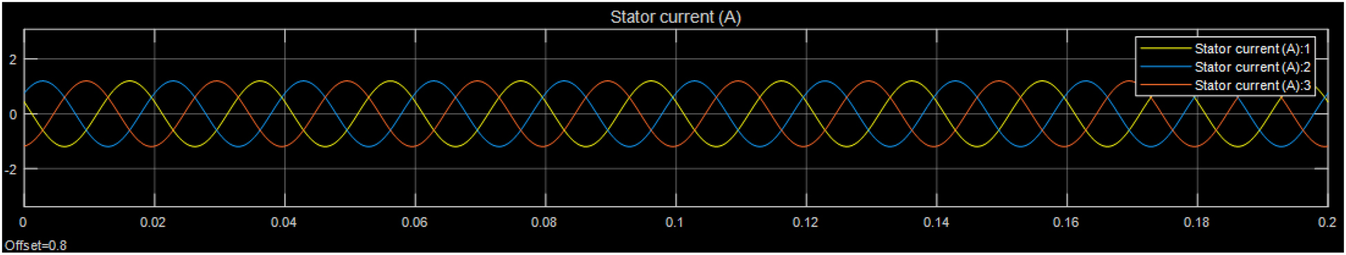
Stator current.

Active power and reactive power generated by DFIG power plant controlled by UPFC.

Three phase voltage.

Three phase current.
The UPFC control circuit is used to eliminate power system fluctuations and improve its transient stability. As can be seen from the simulations, with the sudden change of load connected to the wind turbine, the UPFC control system keeps the DFIG output from severe and long fluctuations and returns the conditions to the desired level with acceptable speed. Note that all the simulated blocks in this article are related to simple DFIG and UPFC models in MATLAB software, the models of these two structures are present in the software by default.
The present paper investigates a wind farm with a dual feed induction generator that is connected to the mains through a back-to-back converter. The generator side converter regulates the generator speed, and the grid side converter controls the reactive power. One of the important issues is the choice of controller for the converters that UPFC has selected.
The proposed control system carefully eliminates the existing fluctuations and shows the excellent effects of UPFC on DFIG. For this purpose, two controllers in the dq stator reference frame are considered for each of the positive and negative components so that UPFC can control precisely Create the correct DFIG components. To evaluate the proposed algorithm, the simulation is performed on a DFIG system in MATLAB/Simulink software environment. The simulation results show that the control algorithm works well despite the network imbalance and also provides the required network power. Finally, the controlled and accurate results without oscillation are shown in Figures 6 and 7 (rotor and stator current), Figure 8 (Active power and reactive power generated by DFIG power plant controlled by UPFC), Figures 9 and 10 (three-phase current and voltage).
Conclusions
This study reviews and introduces a complete description of the latest technologies presented on various types of DFIG controllers, especially UPFC, including models and methods of analysis and control of UPFC in power systems, analysis and classification of present and future, and research trends in This is the context. In this paper, the effect of the Unified Power Flow Controller (UPFC) on a wind turbine with a Dual Feed Induction Generator (DFIG) was investigated. The UPFC uses a combination of a STATCOM parallel controller and an SSSC series controller connected via a DC bus. The simulation results show that by controlling the UPFC series inverter, voltage fluctuations in the PCC bus are prevented and the UPFC parallel inverter injects power after changing the load for faster recovery and stability of the PCC bus voltage and thus the stability of the wind farm. Also, the presence of UPFC in the system reduces power fluctuations.
-
Author contributions: All the authors have accepted responsibility for the entire content of this submitted manuscript and approved submission.
-
Research funding: None declared.
-
Conflict of interest statement: The authors declare no conflicts of interest regarding this article.
References
Abdel-Magid, Y. L., and I. M. El-Amin. 1987. “Dynamic Stability of Wind-Turbine Generators under Widely Varying Loading Conditions.” International Journal of Electrical Power & Energy Systems 9 (3): 180–8, https://doi.org/10.1016/0142-0615(87)90016-0.Search in Google Scholar
Akhmatov, V. 2003. Analysis of Dynamic Behavior of Electric Power Systems with Large Amount of Wind Power. Doctoral diss., PhD diss., Technical University of Denmark, Kgs. Lyngby, Denmark.Search in Google Scholar
de Almeida, R. G., J. P. Lopes, and J. A. L. Barreiros. 2004. “Improving Power System Dynamic Behavior through Doubly Fed Induction Machines Controlled by Static Converter Using Fuzzy Control.” IEEE Transactions on Power Systems 19 (4): 1942–50, https://doi.org/10.1109/tpwrs.2004.836271.Search in Google Scholar
Bongiorno, M., and T. Thiringer. 2013. “A Generic DFIG Model for Voltage Dip Ride-Through Analysis.” IEEE Transactions on Energy Conversion 28 (1): 76–85, https://doi.org/10.1109/tec.2012.2222885.Search in Google Scholar
Georgilakis, P. S., and N. D. Hatziargyriou. 2019. “Unified Power Flow Controllers in Smart Power Systems: Models, Methods, and Future Research.” IET Smart Grid 2 (1): 2–10, https://doi.org/10.1049/iet-stg.2018.0065.Search in Google Scholar
Hansen, A. D., G. Michalke, P. Sørensen, T. Lund, and F. Iov. 2007. “Co‐ordinated Voltage Control of DFIG Wind Turbines in Uninterrupted Operation during Grid Faults.” Wind Energy: An International Journal for Progress and Applications in Wind Power Conversion Technology 10 (1): 51–68, https://doi.org/10.1002/we.207.Search in Google Scholar
Martınez de Alegrıa, I., J. Villate, J. Andreu, I. Gabiola, and P. Ibanez. 2004. “Grid Connection of Doubly Fed Induction Generator Wind Turbines: A Survey.” In EWEA European Wind Energy Conference. Brussels, Belgium.Search in Google Scholar
Morren, J., and S. W. De Haan. 2005. “Ridethrough of Wind Turbines with Doubly-Fed Induction Generator during a Voltage Dip.” IEEE Transactions on Energy Conversion 20 (2): 435–41, https://doi.org/10.1109/tec.2005.845526.Search in Google Scholar
Mullane, A., G. Lightbody, and R. Yacamini. 2005. “Wind-Turbine Fault Ride-Through Enhancement.” IEEE Transactions on Power Systems 20 (4): 1929–37, https://doi.org/10.1109/tpwrs.2005.857390.Search in Google Scholar
Padiyar, K. R. 2007. FACTS Controllers in Power Transmission and Distribution. India: New Age International Publishers.Search in Google Scholar
Qiao, W., R. G. Harley, and G. K. Venayagamoorthy. 2009. “Coordinated Reactive Power Control of a Large Wind Farm and a STATCOM Using Heuristic Dynamic Programming.” IEEE Transactions on Energy Conversion 24 (2): 493–503, https://doi.org/10.1109/tec.2008.2001456.Search in Google Scholar
Qiao, W., G. K. Venayagamoorthy, and R. G. Harley. 2009. “Real-Time Implementation of a STATCOM on a Wind Farm Equipped with Doubly Fed Induction Generators.” IEEE Transactions on Industry Applications 45 (1): 98–107, https://doi.org/10.1109/tia.2008.2009377.Search in Google Scholar
Ren, Y., and W. Zhang. 2011. “A Novel Control Strategy of an Active Crowbar for DFIG-Based Wind Turbine during Grid Faults.” In 2011 IEEE International Electric Machines & Drives Conference (IEMDC), 1137–42. Ontario, Canada: IEEE.10.1109/IEMDC.2011.5994761Search in Google Scholar
Sood, V. K. 2006. HVDC and FACTS Controllers Applications of Static Converters in Power Systems. New York, USA: Kluwer Academic Publishers.Search in Google Scholar
Wang, L., H. W. Li, and C. T. Wu. 2013. “Stability Analysis of an Integrated Offshore Wind and Seashore Wave Farm Fed to a Power Grid Using a Unified Power Flow Controller.” IEEE Transactions on Power Systems 28 (3): 2211–21, https://doi.org/10.1109/tpwrs.2013.2237928.Search in Google Scholar
Yahyaoui, I. 2018. Advances in Renewable Energies and Power Technologies: Volume 1: Solar and Wind Energies, 1st ed. USA: Elsevier.Search in Google Scholar
© 2021 Walter de Gruyter GmbH, Berlin/Boston
Articles in the same Issue
- Frontmatter
- Research Articles
- Performance assessment of a balloon assisted micro airborne wind turbine system
- Effect of unified power flow controller installation in dual feed induction generator (DFIG) wind turbines
- Design and simulation of a MEMS MIM capacitive pressure sensor with high sensitivity in low pressure range
- RWWO: an effective strategy for workflow scheduling in cloud computing with predicted energy using Deep Maxout Network