Theoretical Comparison of Energy Harvesting Methods for Electret-free Variable-Capacitance Devices
-
Aaron L. F. Stein
 ,
Akshay Sarin
,
Akshay Sarin

Abstract
Electret-free variable-capacitance energy harvesters are micro-electromechanical systems (MEMs) that generate electrical power from mechanical vibrations. In order to effectively harvest energy from these devices, the power electronic circuitry is extremely important, and can be the difference between generating or losing energy during a harvesting cycle. Four methods of harvesting energy from these devices are known: the Constant Voltage Method, the Constant Charge Method, the Charge Pump Method, and the Constant Charge With Parallel Capacitance Method. All four methods have been reported; however, the literature is lacking a formal comparison of these methods. This paper evaluates these four methods and the new Voltage and Charge Constrained Method while considering power electronic circuit efficiency as a key parameter. By including efficiency as a parameter, new fundamental properties of these devices are derived: a threshold efficiency necessary for energy harvesting, analytical solutions for optimal harvesting conditions, and a realistic comparison of the four methods. A case study demonstrates the advantage of using the Charge Pump method for MEMs applications, and illustrates the use of the new fundamental properties in the design of a circuit topology that is practical for MEMs vibration energy harvesting applications.
1 Introduction
Recent advancements in communication and low-power sensor nodes have led to innovative data acquisition systems for applications such as heart monitoring, forest-fire detection, and building environmental controls. These sensor nodes play a vital role in human safety and comfort (Akyildiz et al. 2002; Tashiro et al. 2002; Mitcheson et al. 2008). Despite their high utility, sensor nodes are powered by batteries that have limited lifetimes due to finite energy storage. Many sensor networks require placement of nodes in remote locations characterized by limited access to electrical power sources and obstacles which would make replacement of batteries time-consuming and expensive. Harvesting energy from ambient sources such as human movement, acoustic noise, solar radiation, thermal gradients, wind, or vibrations has been shown to be an effective means for recharging sensor batteries (Roundy, Wright, and Rabaey 2003; Mateu and Moll 2005; Raghunathan et al. 2005; Weimer, Paing, and Zane 2006; Pereyma 2007; Chalasani and Conrad 2008; Agbossou et al. 2010). The effectiveness of each of the energy harvesting strategies depends on the device’s environment.
In some environments, mechanical vibration is the most accessible ambient energy source. The viability of a vibration energy source is determined by the magnitude of the acceleration and the frequency of the fundamental mode (Roundy, Wright, and Rabaey 2003). Vibration energy is typically converted into electrical energy using piezoelectric devices, electrostatic devices, or magnetic field-based generators (Roundy, Wright, and Rabaey 2003; Paradiso and Starner 2005; Wang et al. 2009). Some variable-capacitance devices can be easily integrated into microsystems, making them well-suited for harvesting energy for low-power sensor nodes. As discussed by Tiwari, Gupta, and Tiwary (2013), there are two different types of electrostatic devices: electret-free variable capacitance devices and electret-based devices.
The benefit of an electret-based energy harvesting system is that it does not require energy to initiate the energy harvesting cycle; however, electret materials have a finite lifetime (Mescheder et al. 2009). Successful electret-based energy harvesting designs have been demonstrated in Fu and Suzuki (2014a, 2014b). Electret-free variable-capacitance devices require charge to be inserted onto the device in order to initiate energy harvesting. However, they can be fabricated by a silicon process which is compatible with CMOS, allowing for close integration with CMOS electronics (Basset et al. 2009; Sheu, Yang, and Lee 2011; Cowan et al. 2014) and are not limited by the lifetime issues associated with the electret.
Electret-free variable-capacitance devices have many promising characteristics; however, practical difficulties have limited their use (Roundy, Wright, and Rabaey 2003). Challenges such as achieving a large capacitance ratio and a large maximum voltage are compounded by an incomplete understanding of the harvesting methods. In order to reach the full potential of these devices, there must be improvement in both the devices themselves and the harvesting methods by which energy is extracted from them.
Currently the literature provides four energy harvesting methods for these devices. For two of these methods either the voltage (Constant Voltage Method) or charge (Constant Charge Method) is held constant as the device capacitance transitions between its maximum and minimum values. These two methods are discussed at length in Meninger et al. (2001), Harb (2011), Torres et al. (2009), Roundy, Wright, and Rabaey (2004). Examples of circuit topologies that could be used to implement these methods are shown in Harb (2011), Meninger et al. (2001).
Next, the Charge Pump Method is comprised of two voltage sources connected to the device by rectifiers, as demonstrated in Roundy, Wright, and Rabaey (2003), Roundy, Wright, and Pister (2002), Roundy, Wright, and Rabaey (2004). This method was improved when the output voltage source was replaced with a dc-dc converter, eliminating the need for two voltage sources. Both a step-down converter and a flyback converter have been used in this application; however, both of these topologies require an inductor which makes integrating the circuit on a chip very difficult (Yen and Lang 2006; Cowan et al. 2014). To overcome this, (Yen and Lang 2006) propose the use of a switched-capacitor converter to allow a completely integrated energy harvesting system. To optimize the harvesting process (Roundy, Wright, and Rabaey 2003) finds an optimal input voltage for their system through simulation.
Finally, the Constant Charge with Parallel Capacitance Method (CCPC Method) is proposed by Meninger et al. (2001) where both the voltage and charge on the device change as the capacitance changes from its maximum to its minimum value. The CCPC Method is a modification of the Constant Charge Method, whereby an external capacitance is connected in parallel with the device. Through simulation, (Meninger et al. 2001) uncovered the existence of a relationship between circuit losses and the optimal parallel capacitance size. A power electronic interface that could be used to implement this method is proposed in Meninger et al. (2001).
The harvesting methods for electret-free variable-capacitance devices require energy to flow into the device in order to begin the harvesting process. It has been shown for piezoelectric devices, whose harvesting methods require energy flow into the device, that power electronic efficiency plays a large role in device performance and optimal operating conditions (Liu et al. 2009). However, the effect of circuit efficiency on variable-capacitance energy harvesting has not been formally examined in the literature for any of the above-mentioned harvesting methods.
The purpose of this paper is to determine how power electronic circuit efficiency affects energy harvesting for variable-capacitance devices. The energy harvesting capabilities of these devices are constrained by their physical limitations, as discussed in Section 2. While considering these limitations Section 3 uncovers the energy harvesting capabilities of existing harvesting methods and a new harvesting method, the Voltage and Charge Constrained (VCC) Method, as a function of power electronic circuit efficiency. This analysis reveals that each method has a threshold efficiency required to achieve energy harvesting. Furthermore, analytical solutions for computing the optimal parallel capacitance for the CCPC Method, and the optimal input voltage for the Charge Pump Method as a function of power electronic efficiency, provide insights into the design of effective energy energy harvesting systems. Finally, in Section 4, a micro-sized harvesting system is proposed. This system is based on the Charge Pump Method, which advances the system in Yen and Lang (2006) by providing a design which can be synthesized entirely in silicon and incorporates the optimal harvesting conditions derived in this paper.
2 Electret-Free Variable-Capacitance Devices
A variable-capacitance energy harvesting device is an electromechanical system in which a mass (
There are two common types of variable capacitance devices.
An area-overlap device, in which the mechanical vibrations cause the overlapping area of the electrodes to change; an example is shown in Figure 1(a) (Roundy, Wright, and Rabaey 2004). For this device, the length of the overlapping region changes as a function of the position of the mass (
A gap-closing device, in which the mechanical vibrations cause the distance
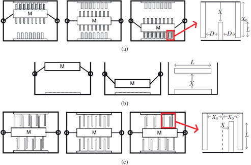
Physical model of an area-overlap and a gap-closing variable-capacitance energy harvesting devices. (a) Area-overlap Device (b) Out-Of-Plane Gap-closing Device (c) In-Plane Gap-closing Device.
As either the area of overlap or distance between the electrodes change, so too does the capacitance of the device. Based on the magnitude of the ambient vibrations, the variable capacitance device will achieve a maximum capacitance (
The literature provides expressions for the ideal energy harvested per mechanical cycle for each of the four methods of energy harvesting. These equations are derived after making a quasi-static assumption, meaning here that the electrical energy harvesting does not affect the mechanical displacement. This assumption does not prohibit dynamic analysis: redefining
2.1 Variable-Capacitance Device Constraints
To estimate the energy harvesting capabilities of a variable-capacitance device, appropriate constraints must be considered. These constraints are inherent to the devices, and are necessary for understanding the energy harvesting limitations of said devices.
In many cases, the energy harvesting capabilities of variable-capacitance devices are limited by its structural properties. Stored energy in the variable-capacitance device creates an electrostatic force between the electrodes. As the energy in the device increases, so too does the force on the electrodes of the device. If the stored energy becomes too large, the resulting force on the electrodes could cause physical deformation of the device (e. g., pull-in effect) (Mescheder et al. 2012).
In order to avoid device failure and harvest energy, force constraints must be placed on the device. The force in a variable capacitance device is derived from the co-energy of the electric field (
Deriving the electrostatic force expression for each device will illuminate the electrical constraints that must be considered in order to avoid mechanical failure. The electrical constraint which must be applied to each device considered in this manuscript can be found in Table 1.
2.1.1 Area-Overlap Electrical Device Constraint
For an area-overlap device, such as the one depicted in Figure 1(a), the maximum allowable voltage across the device is an important device constraint. Assuming linear motion of parallel plates, the device capacitance changes as a function of position (
Substituting the capacitance equation into eq. [3], the electrostatic force is given by
The force between the electrodes in an area-overlap device is therefore dependent on the physical device parameters and the voltage on the device (
The maximum voltage limitation on a area-overlap device constrains the energy storage capabilities of the device. For a given
The maximum energy that can be stored in the device provides an upper bound on the amount of energy that can be harvested. This is established in Section 3.5, where it is shown that for certain harvesting methods, as
2.1.2 Gap-Closing Electrical Device Constraint
Let us first consider an out-of-plane gap-closing device, such as the one depicted in Figure 1(b). The capacitance in this device is given by
Assuming linear motion of parallel plates, and using eq. [3], the electrostatic force in the device is
For a given out-of-plane gap-closing device,
For an in-plane gap-closing device such as the one illustrated in Figure 1(c) the capacitance of the device is given by
The largest electrostatic force will occur when the mass is significantly displaced; i. e., when X approaches
Therefore the electrostatic force can be approximated by
Once again,
The maximum charge limitation on a gap-closing device constrains the energy storage capabilities of the device. For a given
Once again, the maximum energy that can be stored in the device provides an upper bound on the amount of energy that can be harvested. This is also confirmed for gap-closing devices in Section 3.5 of the sequel.
Variable-capacitance device constraints.
| Device type | Constraint | Maximum energy |
| Area-overlap device | Voltage |
|
| Out-of-plane gap-closing device | Charge |
|
| In-plane gap-closing device | Charge |
|
2.1.3 Efficiency-Based Analytical Tools
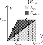
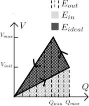
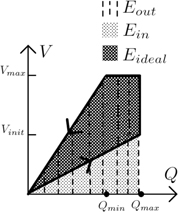
To understand the energy harvesting capabilities of these devices, first consider the amount of energy that can be extracted assuming 100 % efficient power electronics (ideal energy harvested). The expression for the ideal energy harvested over an energy harvesting cycle is given by:
The ideal energy harvested accounts for the electrical energy supplied to the harvesting device,
For each harvesting method a voltage versus charge plot will be shown. The net area enclosed by the voltage versus charge plot is
In order to take into account losses in the power electronic circuitry, the input and output energy of the device are penalized by an efficiency
The net energy equation is normalized by the maximum the maximum possible energy that can be extracted from the device. The normalized net energy
The normalized net energy equation is derived to illustrate the energy harvesting capabilities of each method independent of specific device parameters. It should be noted that
Comparisons between voltage-limited and charge-limited devices are also possible, assuming the maximum energy harvesting densities of the devices are identical. In Roundy, Wright, and Rabaey (2004) it is claimed that the energy harvesting density of area-overlap devices and gap-closing devices are roughly the same, while in Lee et al. (2009) it is claimed that area-overlap devices have a slightly higher energy density. Either way, the normalized net energy harvested provides a basis for comparison between the different energy harvesting methods and device architectures.
As will be shown, each method has a threshold power electronic efficiency,
3 Efficiency-based Analysis for Energy Harvesting Methods
3.1 Constant Voltage Method
The Constant Voltage Method charges the capacitive device to a voltage Vmax when the capacitance is at its maximum value so that the charge on the device is given by:
As the device’s capacitance is reduced to its minimum value, the voltage across it is held constant at
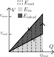
Finally, once the device reaches its minimum capacitance, the voltage on the device is reduced to zero (Meninger et al. 2001). The voltage and charge fluctuations of this process are illustrated in Figure 2.
Voltage versus charge plot for the Constant Voltage Method.
3.1.1 Voltage-Limited
Using eq. [13], the energy into and out of a voltage-limited device can be derived directly from the shaded areas shown in Figure 2:
The net energy harvested is therefore:
Using eq. [15], the normalized energy harvested is derived:
The normalized net energy is plotted in Figure 3 and illustrates how efficiency affects energy harvesting for the voltage limited Constant Voltage Method. Given highly efficient power electronics and a device with a large
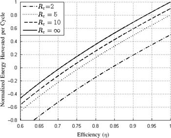
The voltage-limited normalized net energy harvested,
3.1.2 Charge-Limited
Using eq. [13], the ideal energy harvested from a charge-limited device using the Constant Voltage Method is
Including the efficiency of the power electronics, the net energy harvested is
The normalized net energy
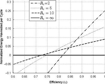
The charge-limited normalized net energy harvested,
The normalized net energy is plotted in Figure 4, and illustrates how efficiency affects energy harvesting for the Constant Voltage Method on a charge-limited device. As the capacitance ratio increases, the Constant Voltage Method harvests only a small fraction of the available energy independent of power electronic efficiency.
3.1.3 Threshold Efficiency
The threshold efficiency for the Constant Voltage Method is given by:
A good variable-capacitance harvesting device has a
A capacitance ratio of 25 or higher is sufficiently large for eq. [28] to be a good approximation of the threshold efficiency.
3.2 Constant Charge Method
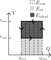
The Constant Charge Method of energy harvesting charges the device to a voltage
Voltage versus charge plot for the Constant Charge Method.
The voltage on the device is inversely proportional to the capacitance during the constant charge part of the cycle. The maximum voltage experienced by the device is derived in eq. [29].
3.2.1 Voltage-Limited
In order to prevent the voltage from exceeding the voltage limit,
Using eqs [14] and [32] to solve for the net energy harvested yields:
Using eq. [15], the normalized net energy harvested is shown to be:
A plot of eq. [36] is shown in Figure 6 to elucidate some of the trends. It can be shown that the highest ratio of harvested energy to available energy is when the power electronic efficiency is high and the capacitance ratio has a value of 2. In this case, the Constant Charge method harvests a quarter of the maximum available energy. As the capacitance ratio becomes large, the Constant Charge Method harvests very little energy relative to the available energy. In this case we see that
The voltage-limited normalized energy harvested,
3.2.2 Charge-Limited
The net energy harvested using the Constant Charge Method on a charge-limited device is
Using eq. [15], the normalized net energy harvested is shown to be
Figure 7 illustrates the normalized net energy harvested as a function of power electronic efficiency. Several important trends for the Constant Charge Method are illuminated. First, for large capacitance ratios the normalized net energy is
The charge-limited normalized net energy harvested,
For this case, the power electronic efficiency essentially only impacts the energy extracted from the system. Therefore, power electronic efficiency has a reduced importance on the harvesting performance of this method. Next, at high efficiencies and large capacitance ratios, this method can harvest up to 100 % of the available energy. Finally, for devices with smaller capacitance ratios, the Constant Charge method can still harvest an appreciable amount of power; however, as
3.2.3 Threshold Efficiency
The Constant Charge Method can harvest energy over a very wide efficiency range. The threshold efficiency is
As the capacitance ratio becomes large, the threshold efficiency for the Constant Charge Method is
3.3 Charge Pump Method
The Charge Pump Method energy harvesting cycle starts at an initial voltage
The device is then open-circuited, undergoing a constant-charge phase until the voltage on the device reaches
Once the device has reached
In order to harvest energy using the Charge Pump Method,
Voltage versus charge plot for the Charge Pump Method.
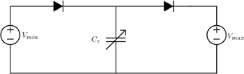
Diode-based Charge Pump Method energy harvesting circuit.
The conditions noted in eq. [42] are developed from fundamental circuit principles. First,
3.3.1 Voltage-Limited
The terms
Including efficiency as a parameter as demonstrated in eq. [14], the net harvested energy is given by:
The net energy equation for the Charge Pump Method is a function of two controllable design criteria:
In eq. [47], it is shown that
Using
![Figure 10:
The voltage-limited normalized net energy harvested using the Charge Pump Method is plotted as a function of efficiency, while Vmax is limited and Vmin is optimized. If the method constraint in eq. [42] is violated, the normalized net energy harvested is plotted as zero.](/document/doi/10.1515/ehs-2015-0020/asset/graphic/j_ehs-2015-0020_fig_059.jpg)
The voltage-limited normalized net energy harvested using the Charge Pump Method is plotted as a function of efficiency, while Vmax is limited and Vmin is optimized. If the method constraint in eq. [42] is violated, the normalized net energy harvested is plotted as zero.
The normalized net energy equation is only valid when, for the given harvesting conditions, the equation for
It is illustrated that, for large values of
3.3.2 Charge-Limited
The net energy harvested using the Charge-Pump Method on a charge-limited device is
The net energy equation can be maximized through careful selection of
Combining
Once again the normalized net energy equation is only valid when the selection of
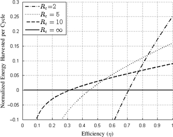
The normalized net energy harvested is plotted in Figure 11. At high efficiencies, the charge pump method used on charge-limited variable-capacitance devices with large capacitance ratios can harvest up to 50 % of the maximum energy.
![Figure 11:
The charge-limited normalized net energy harvested, NEnet${N_{Enet}}$, using the Charge Pump Method is plotted as a function of efficiency (η$\eta $) for various values of capacitance ratio (Rc${R_c}$). If the method constraint in eq. [42] is violated, the normalized net energy harvested is plotted as zero.](/document/doi/10.1515/ehs-2015-0020/asset/graphic/j_ehs-2015-0020_fig_063.jpg)
The charge-limited normalized net energy harvested,
3.3.3 Threshold Efficiency
Finally, to ensure a positive net energy harvested, the threshold efficiency is given by:
For this method the threshold efficiency is determined by
3.4 Constant Charge with Parallel Capacitance (CCPC) Method
The Constant Charge with Parallel Capacitance Method, or CCPC Method, is very similar to that of the Constant Charge Method, with the exception that a capacitor is placed in parallel with the device. The parallel capacitor aids in energy harvesting because it allows the variable-capacitance device to undergo a change in both voltage and charge (Lee et al. 2009). For the CCPC Method, the device and the parallel capacitor are charged to
Voltage versus charge plot for the Constant Charge with Parallel Capacitance Method.
3.4.1 Voltage-Limited
The shaded enclosed areas in Figure 12 represent
where
The ideal energy extracted is given by:
We assume that energy transfer between the two capacitors, when they are in the open-circuit configuration, is considered to occur without loss. Using eq. [14] an equation for
In Meninger et al. (2001) it was shown through simulation that there exists an optimal
The relationship between
Optimal
Using the optimal
The voltage-limited normalized net energy harvested plotted as a function of efficiency while using the optimal
Given highly-efficient power electronics and a device with a large
3.4.2 Charge-Limited
The CCPC method is not an effective method of energy harvesting for a charge-limited device. The parallel capacitance increases the input energy into the device, and does not provide any benefit to the energy harvesting process.
3.4.3 Threshold Efficiency
The threshold efficiency for the CCPC Method is given by:
Similar to the Constant Charge Method, as the capacitance ratio becomes arbitrarily large,
3.5 Comparison of Methods
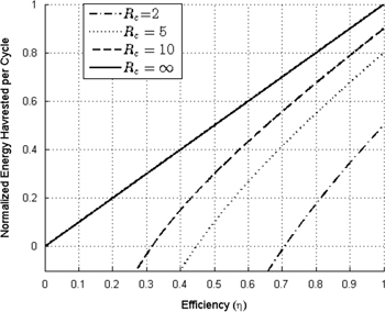
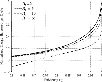
In the following comparison of energy harvesting methods, it is assumed that the maximum energy harvesting density of a charge-limited device and a voltage-limited device is the same, as suggested in Roundy, Wright, and Rabaey (2004). Although in practice there may be some difference, this assumption provides a grounds for comparison of the normalized net energy harvested. The normalized net energy harvested for the discussed methods on a device with a very large capacitance ratio is shown in Figure 15.
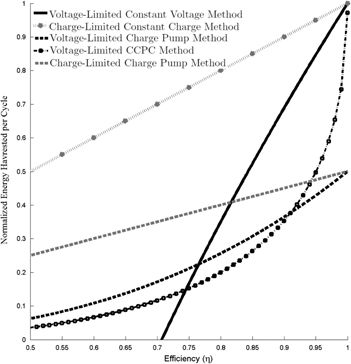
A comparison of the normalized net energy harvested is shown as a function of power electronic efficiency for the more promising method and device architecture combinations. The normalized net energy is plotted using an infinite capacitance ratio, to show the best harvesting scenario for each method.
The Constant Voltage method on a voltage-limited device, and the Constant Charge method on a charge-limited device, both have a maximum normalized net energy that approaches 1 at high efficiencies. Given the physical constraints of the device, both methods utilize the entire constraint boundary for energy harvesting (
The Constant Voltage method on a charge-limited device, and the Constant Charge method on a voltage-limited device, both have a normalized net energy that is small even at high efficiencies. This is because these combinations of harvesting methods and device constraints limit the utilized constraint boundary when the device is at
The Charge Pump method has a maximum normalized net energy of 0.5, which illuminates an important upper bound on the capabilities of this method. The energy harvesting capabilities of the Charge Pump Method are limited by the fact that it is a passive cycle. The voltage and charge are not driven to zero when the device capacitance is at
The CCPC Method on a voltage-limited device has a normalized net energy harvested that approaches 1. Once again, this method utilizes the entire constraint boundary (
Figure 15 illustrates important conclusions about the various energy harvesting methods. This plot shows that:
At 100 % efficiency the charge-limited Constant Charge Method, the voltage-limited Constant Voltage Method, and the CCPC Method can all harvest 100 % of the available power.
At 100 % efficiency the Charge Pump method harvests up to 50 % of the available power for both voltage and charge limited devices.
The Constant Charge method is less impacted by efficiency than the Constant Voltage method.
Charge constrained portions of energy harvesting cycles are less impacted by circuit efficiency. During the constant charge portion of the energy harvesting cycle, the device is in an open-circuit configuration, and therefore is not impacted by the efficiency of the electronics as there is no power flow. Conversely, voltage constrained portions of energy harvesting methods have power flow. The constrained voltage is generated using power electronics, and therefore the harvested energy is more impacted by the efficiency of the power electronics.
3.6 Voltage and Charge Constrained (VCC) Method
The Constant Charge Method on a charge-limited device harvests the most energy of any method at practical power electronic efficiencies; however, energy harvesting systems that utilize this device architecture and harvesting method typically produce large voltages. For example, in Mitcheson et al. (2004) a gap-closing device is used with the Constant Charge method. The experimental results show device voltages in excess of 350 volts. In such a system, the maximum charge should be limited to limit the pull-in effect, but also the maximum voltage may need to be limited to accommodate the silicon process that creates the device, or the power electronic circuitry which implements the energy harvesting method. In order to meet both constraints, a new energy harvesting method is proposed, the Voltage and Charge Constrained (VCC) Method.
The VCC Method charges the gap-closing device to
The device is then open-circuited and, as the device capacitance declines, the voltage on the device increases. Once the voltage on the device reaches the maximum allowable voltage
The resulting voltage-versus-charge plot for the VCC Method is illustrated in Figure 16.
The voltage versus charge plot is shown for the Voltage and Charge Constrained method of energy harvesting.
A new factor,
The constrained maximum voltage
The net energy equation is then derived in terms of
The net energy equation is normalized by the maximum possible energy in the electrical system when K is equal to 1, which is
The normalized net energy harvested is therefore
The impact of constraining the maximum voltage is elucidated by plotting the normalized net energy harvested as a function power electronic efficiency and
The VCC Method seeks to mitigate the maximum voltage in the system while still providing the energy harvesting benefits of the Constant Charge Method on a charge-limited device. For example consider a device with a very large capacitance ratio. At its best (
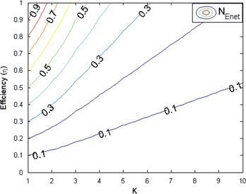
The normalized net energy harvested using the VCC Method is plotted as a function of both power electronic efficiency and K for a variable-capacitance device with a large capacitance ratio (
The threshold efficiency for the VCC Method is
A possible implementation of the VCC Method can be created through modification of the circuit topology presented for the Constant Charge Method in Meninger et al. (2001). A diode connects a large capacitor, which is charged to
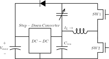
Proposed circuit topology that implements the Voltage and Charge Constrained Method.
4 Case Study
In this section a case study is presented to demonstrate an application of the fundamental principles presented in this manuscript. The goal of this case study is to maximize the harvested power for a micro-sized energy harvesting system. To achieve this goal, the energy harvesting device is designed such that it can be integrated with both the power electronics and the wireless sensor node made using a CMOS process. This integration poses two challenges:
the power electronic circuit should be designed such that it can be implemented entirely in silicon
the maximum voltage in the system is limited by the CMOS process.
Due to these restriction an area-overlap device architecture is chosen, so that the voltage constraint can be accommodated. The device parameters are based on the device used in Meninger et al. (2001), and are shown in Table 2.
Area-overlap device parameters used in case study
| Parameter | Value |
| Allowable |
8 V |
| C max | 260 pF |
| C min | 2 pF |
| Frequency | 2,520 Hz |
The device is a comb-type variable-capacitance device that is excited at a frequency of 2,520 Hz, meaning the device varies from
4.1 Selecting a Harvesting Method for a Micro-Sized Energy Harvester
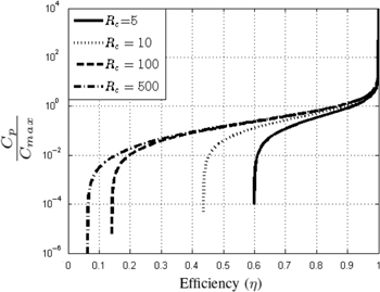
In order to select the best harvesting method, a number of factors must be considered: power harvested, practicality of implementation, and ease of integration into a micro-sized energy harvester. As the device is voltage-limited only, charge-limited energy harvesting methods are not considered (including the VCC Method). Figure 19 highlights the Constant Voltage Method, the CCPC Method, and the Charge Pump method because they each harvest a significant amount of power over a wide efficiency range. However, the Constant Voltage Method and CCPC Method are practically difficult to implement. These methods require the device to be charged and discharged when the oscillating mass of the device is at a certain position. This requires the controller to have knowledge of the position of the energy harvester. Such a control strategy was developed by Meninger et al. (2001); however, 34 % of their harvested power was dedicated to their controller implementation. Even if a highly-efficient control circuit and power electronic converter was developed for these methods, the varying nature of the voltage on the device as energy is transferred back to the battery would require a magnetic-component-based power electronic circuit. This can be difficult to implement in a microsystem, as it requires a micro-sized magnetic core that is difficult to manufacture on a chip. In (Meninger et al. 2001) an estimated 5.6 μW could be harvested from the area-overlap device using the CCPC Method. If the Charge Pump Method was used in combination with the optimal minimum voltage shown in eq. [47], then based on eq. [46] we expect to harvest 10.8 μW from the same device given an assumed efficiency estimate of 80 % (
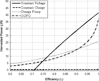
Comparison of power harvested for each harvesting methods using the area-overlap (voltage-limited) device presented in Table 2 assuming optimized conditions for the Charge Pump and CCPC methods. The Constant Charge Method harvests 0.32 μW at
The Charge Pump Method has many advantages: it can be easily implemented on an integrated circuit, does not require active control, and it harvests significant energy over a wide efficiency range. The optimum ratio of
4.2 Design of a Voltage-Limited Energy Harvesting System
In order to maximize the power harvested, it is important that the design of the energy harvesting system is closely tied to the optimal harvesting conditions derived in eq. [47]. Assuming 100 % efficiency and a
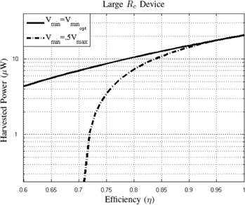
Comparison of power harvested using the
As the device capacitance oscillates between
4.3 Simulation Results
The energy harvesting system portrayed in Figure 21 was simulated in LTSPICE. The simulation included many realistic loss mechanisms in order to provide an accurate estimate of power harvested. An appropriate loss model was created based on loss mechanisms associated with implementing this design on an integrated circuit. The switches required in this design are bi-directional switches which must be able to hold 10 Volts and carry 20 mA. In order to withstand the required voltage range a 12 Volts process was used for the design. Using models of this process, parameter values for the transistors were extracted. These transistors have an on-resistance of 257 mΩ (when
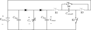
Charge Pump Method energy harvesting circuit topology with switched-capacitor energy return.
The results of this simulation are summarized in Table 3 and Figure 22, which shows the output voltage rising as energy is harvested from the device. Once the voltage reaches the top of the hysteresis band, the switched-capacitor converter is enabled and energy is returned to the source.
LTSPICE simulation results for the area-overlap device, using the Charge Pump Method with a switched-capacitor topology.
| Simulation results | |
| Switched-capacitor efficiency | 86.9 % |
| Energy harvested | 12.09 μW |
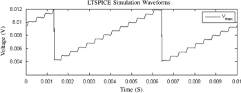
Using the theory developed in this paper, an energy harvesting system that could be used for a micro-sized energy harvester was developed that harvests 12.09 μW, more than twice the amount of energy as predicted in Meninger et al. (2001) while using the same device properties.
5 Summary and Conclusion
Electret-free variable-capacitance energy harvesting devices are proposed as a solution for charging wireless sensor nodes from ambient vibrations because they can be made in silicon, are easily integrated with CMOS electronics in a micro-sized harvesting system, and do not have a limited lifetime; however, the small available power from these devices has limited their use. This work seeks to increase the viability of electret-free variable-capacitance energy harvesters by maximizing the power harvested from these devices. This was accomplished by incorporating power electronic efficiency into the existing analysis of the harvesting methods. Including power electronic efficiency as a parameter leads to: the derivation of a threshold efficiency for each of the energy harvesting methods, a comparison of the net energy harvested using different harvesting methods over a wide efficiency range, and analytical solutions for the optimal harvesting conditions for applicable methods.
The new theoretical background developed in this paper motivates the design of an energy harvesting system using a voltage-limited device with the Charge Pump Method. Analytical solutions for optimal energy harvesting conditions inspired the use of a 2:1 switched capacitor converter topology as the basis of the voltage-limited harvesting system. An LTSPICE simulation verified the advantages of the proposed Charge Pump Method harvesting system by revealing that 12.09 μW could be harvested from this system, which is more than twice the power previously asserted for the same device.
Ultimately, an in-depth understanding of the power electronic efficiency is key to maximizing the energy harvested from these devices. Future research in this area will focus on incorporating mechanical dynamics into this efficiency-based analysis of the energy harvesting methods.
References
Agbossou, A., Q. Zhang, G. Sebald, and D. Guyomar. 2010. “Solar Micro-Energy Harvesting Based on Thermoelectric and Latent Heat Effects. Part I: Theoretical Analysis.” Sensors and Actuators A: Physical 163:277–83.10.1016/j.sna.2010.06.026Search in Google Scholar
Akyildiz, I. F., W. Su, Y. Sankarasubramaniam, and E. Cayirci. 2002. “Wireless Sensor Networks: A Survey.” Computer Networks 38:393–422.10.1016/S1389-1286(01)00302-4Search in Google Scholar
Basset, P., D. Galayko, A. M. Paracha, F. Marty, A. Dudka, and T. Bourouina. 2009. “A Batch-Fabricated and Electret-Free Silicon Electrostatic Vibration Energy Harvester.” Journal of Micromechanics and Microengineering 19:115025.10.1088/0960-1317/19/11/115025Search in Google Scholar
Chalasani, S., and J. M. Conrad. 2008. “A Survey of Energy Harvesting Sources for Embedded Systems.” In IEEE Southeastcon, 442–7.Search in Google Scholar
Cowan, J. J., and G. Rincon-Mora. 2014. “Harvesting the Highest Power from tiny Electrostatic Transducers with CMOS Circuits.” In Circuits and Systems (MWSCAS), IEEE, 334–7.10.1109/MWSCAS.2014.6908420Search in Google Scholar
Despesse, G., T. Jager, J. -J. Chaillout, J. -M. Leger, and S. Basrour. 2005. “Design and Fabrication of a New System for Vibration Energy Harvesting.” In Research in Microelectronics and Electronics, 2005 PhD, volume 1, IEEE, volume 1, 225–8.Search in Google Scholar
Fu, Q., and Y. Suzuki. 2014a. “A Design Method of In-Plane MEMS Electret Energy Harvester with Comb Drives.” In Journal of Physics: Conference Series, volume 557, IOP Publishing, volume 557, 012011.10.1088/1742-6596/557/1/012011Search in Google Scholar
Fu, Q., and Y. Suzuki. 2014b. “MEMS Vibration Electret Energy Harvester with Combined Electrodes.” In Micro Electro Mechanical Systems (MEMS), 2014 IEEE 27th International Conference on, IEEE, 409–12.10.1109/MEMSYS.2014.6765663Search in Google Scholar
Harb, A. 2011. “Energy Harvesting: State-of-the-Art.” Renewable Energy 36:2641–54.10.1016/j.renene.2010.06.014Search in Google Scholar
Lee, C., Y. M. Lim, B. Yang, R. K. Kotlanka, C. -H. Heng, J. H. He, M. Tang, J. Xie, and H. Feng. 2009. “Theoretical Comparison of the Energy Harvesting Capability Among Various Electrostatic Mechanisms From Structure Aspect.” Sensors and Actuators A: Physical 156:208–16.10.1016/j.sna.2009.02.024Search in Google Scholar
Liu, Y., G. Tian, Y. Wang, J. Lin, Q. Zhang, and H. Hofmann. 2009. “Active Piezoelectric Energy Harvesting: General Principle and Experimental Demonstration.” Journal of Intelligent Material Systems and Structures 20:575–585. Sage Publications.10.1177/1045389X08098195Search in Google Scholar
Mateu, L., and F. Moll. 2005. “Review of Energy Harvesting Techniques and Applications for Microelectronics (Keynote Address).” In Microtechnologies for the New Millennium 2005, International Society for Optics and Photonics, 359–73.10.1117/12.613046Search in Google Scholar
Melcher, J. R. 1981. Continuum Electromechanics, volume 2. Cambridge: MIT press.Search in Google Scholar
Meninger, S. 1999. A Low Power Controller for a MEMS based Energy Converter. Ph.D. thesis, Massachusetts Institute of Technology.Search in Google Scholar
Meninger, S., J. Mur-Miranda, R. Amirtharajah, A. Chandrakasan, and J. H. Lang. 2001. “Vibration-to-Electric Energy Conversion.” IEEE Transactions on Very Large Scale Integration (VLSI) Systems 9:64–76.10.1109/92.920820Search in Google Scholar
Mescheder, U., B. Müller, S. Baborie, and P. Urbanovic. 2009. “Properties of SiO2 Electret Films Charged by Ion Implantation for MEMS-Based Energy Harvesting Systems.” Journal of Micromechanics and Microengineering 19:094003.10.1088/0960-1317/19/9/094003Search in Google Scholar
Mescheder, U., A. Nimo, B. Müller, and A. S. A. Elkeir. 2012. “Micro Harvester Using Isotropic Charging of Electrets Deposited on Vertical Sidewalls for Conversion of 3D Vibrational Energy.” Microsystem Technologies 18:931–43.10.1007/s00542-011-1418-4Search in Google Scholar
Mitcheson, P. D., P. Miao, B. H. Stark, E. Yeatman, A. Holmes, and T. Green. 2004. “MEMS Electrostatic Micropower Generator for Low Frequency Operation.” Sensors and Actuators A: Physical 115:523–9.10.1016/j.sna.2004.04.026Search in Google Scholar
Mitcheson, P. D., E. M. Yeatman, G. K. Rao, A. S. Holmes, and T. C. Green. 2008. “Energy Harvesting From Human and Machine Motion for Wireless Electronic Devices.” Proceedings of the IEEE 96:1457–86.10.1109/JPROC.2008.927494Search in Google Scholar
Paradiso, J. A., and T. Starner. 2005. “Energy Scavenging for Mobile and Wireless Electronics.” Pervasive Computing, IEEE 4:18–27.10.1109/MPRV.2005.9Search in Google Scholar
Peano, F., and T. Tambosso. 2005. “Design and Optimization of a MEMS Electret-Based Capacitive Energy Scavenger.” IEEE/ASME Journal of Microelectromechanical Systems 14:429–35.10.1109/JMEMS.2005.844803Search in Google Scholar
Pereyma, M. 2007. “Overview of the Modern State of the Vibration Energy Harvesting Devices.” In Perspective Technologies and Methods in MEMS Design, 2007. MEMSTECH 2007. International Conference on, IEEE, 107–12.10.1109/MEMSTECH.2007.4283437Search in Google Scholar
Raghunathan, V., A. Kansal, J. Hsu, J. Friedman, and M. Srivastava. 2005. “Design Considerations for Solar Energy Harvesting Wireless Embedded Systems.” In Proceedings of the 4th international symposium on Information processing in sensor networks, IEEE Press, 64.Search in Google Scholar
Roundy, S., P. K. Wright, and K. S. Pister. 2002. Micro-Electrostatic Vibration-to-Electricity Converters, 487–96.10.1115/IMECE2002-39309Search in Google Scholar
Roundy, S., P. K. Wright, and J. Rabaey. 2003. “A Study of Low Level Vibrations as a Power Source for Wireless Sensor Nodes.” Computer Communications 26:1131–44.10.1016/S0140-3664(02)00248-7Search in Google Scholar
Roundy, S., P. Wright, and J. Rabaey. 2004. Energy Scavenging for Wireless Sensor Networks: With Special Focus on Vibrations. Springer US. https://books.google.com/books?id=PmmvRsfsUKcC.10.1007/978-1-4615-0485-6Search in Google Scholar
Sheu, G. -J., S. -M. Yang, and T. Lee. 2011. “Development of a Low Frequency Electrostatic Comb-Drive Energy Harvester Compatible to SoC Design by CMOS Process.” Sensors and Actuators A: Physical 167:70–6.10.1016/j.sna.2010.07.013Search in Google Scholar
Tashiro, R., N. Kabei, K. Katayama, E. Tsuboi, and K. Tsuchiya. 2002. “Development of an Electrostatic Generator for a Cardiac Pacemaker That Harnesses the Ventricular Wall Motion.” Journal of Artificial Organs 5:239–45.10.1007/s100470200045Search in Google Scholar
Tiwari, R., M. Gupta, and O. P. Tiwary. 2013. “Study of Different Energy Scavenging Techniques through Vibration and Its Micro Power Applications.” International Journal of Computer Applications 68:17–23.10.5120/11688-7384Search in Google Scholar
Torres, E. O., G. Rincón-Mora. 2009. “Electrostatic Energy-Harvesting and Battery-Charging CMOS System Prototype.” Circuits and Systems I: Regular Papers, IEEE Transactions on 56:1938–48.10.1109/TCSI.2008.2011578Search in Google Scholar
Wang, G., C. Luo, H. Hofmann, and L. Rome. 2009. “Power Electronic Circuitry for Energy Harvesting Backpack.” In Energy Conversion Congress and Exposition, 2009. IEEE, 3544–9.Search in Google Scholar
Weimer, M. A., T. S. Paing, and R. A. Zane. 2006. “Remote Area Wind Energy Harvesting for Low-Power Autonomous Sensors.” In Power Electronics Specialists Conference, 2006. IEEE, 1–5.10.1109/pesc.2006.1712213Search in Google Scholar
Yen, B. C., and J. H. Lang. 2006. “A Variable-Capacitance Vibration-to-Electric Energy Harvester.” Circuits and Systems I: Regular Papers, IEEE Transactions on 53:288–95.10.1109/TCSI.2005.856043Search in Google Scholar
©2016 by De Gruyter
Articles in the same Issue
- Frontmatter
- How Much Energy Needs for Running Energy Harvesting Powered Wireless Sensor Node?
- Autonomous Sensor Node Powered by CM-Scale Benthic Microbial Fuel Cell and Low-Cost and Off-the-Shelf Components
- Oxide-Based Thermoelectric Generator for High-Temperature Application Using p-Type Ca3Co4O9 and n-Type In1.95Sn0.05O3 Legs
- Powering In-pipe Wireless Sensors Using Flexible Piezoelectric Micro-generators
- Ultrafast Anisotropic Optical Response and Coherent Acoustic Phonon Generation in Polycrystalline BaTiO3-BiFeO3
- BiFeO3/BaTiO3 Multilayer Structures for Solar Energy Harvesting Application
- Theoretical Comparison of Energy Harvesting Methods for Electret-free Variable-Capacitance Devices