Compound Piezomechanical Systems of Algae Cell Disrupting
-
Piotr Vasiljev
 ,
Arunas Struckas
,
Arunas Struckas

Abstract
One of the most attractive sources of raw materials for biofuel production can be algae oil processing into biofuels. In this paper, the authors are proposing a unique ultrasonic piezoelectric system, which would allow the reduction of internal energy losses and concentration of ultrasonic energy into a small closed volume. The current vibrating systems whose ultrasonic energy is concentrated inside of a hollow cylinder where the water–algae mixture is flowing. The ultrasonic energy is concentrated in a local volume to create a high-power bubble implosion process. Two, three or multiple ultrasonic composite systems to concentrate the total energy into a hollow cylinder in order to create a strong algae cell ultrasonication are used. The experiments and the numerical finite element method (FEM) analysis results using the proposed transducers as well as the biological test results on algae cell disruption by ultra-sonication are presented in this paper.
Introduction
One of the most attractive sources of raw materials for biofuel production can be algae oil processing into biofuels. Under favorable conditions many species of algae can be propagated twice per day and have been proven possible to produce a lot of oil at a very quick rate. However, algae cultivation and efficient recycling of bioproducts has been a complex, time-consuming and expensive process so far. Strong algae cell walls protect from external stresses and allow them to survive, which complicates the issue of oil extraction.
Nowadays, the fuel production from algae uses enzymatic disaggregation, chemical degradation or mechanical-based technology. The algae wall ultrasonic disintegrators are widely used to disrupt cells using ultrasonic systems in mechanical-based technology (Peshkovsky and Peshkovsky, 2007, 2010; Peshkovsky and Peshkovsky; http://sonomechanics.com/technology/ultrasonic_horn_designs_and_properties/). These devices use longitudinal vibrations to generate a high-level ultrasonic wave pressure in liquid media, and in the case of biofuel production, algae cells in water. Under the right conditions the pressure waves cause the formation of cavitation processes, whereby microbubble implosion generates a shock wave with enough energy to break cell membranes and even break covalent bonds.
The aim of this work is the creation of compound ultrasonic systems that would reduce the waste of vibration energy, concentrating it in a closed volume. The ultrasonic energy is concentrated in a local volume to create a high power cavitation process. Their usage enables to concentrate microbubble implosion into an inner part of a cylinder and increases vibration amplitudes in large closed space.
Piezomechanical Systems
Compound Plane Design System
The rated power output and used resonance rates of ultrasonic processors vary highly. The minimal mechanical vibration amplitude of the ultrasonic system should be about 15 µm (Prohorenko et al. 1981). The longitudinal vibration amplitudes of industrial algae cell disintegrators are from 25 to 90 µm (peak-to-peak), and the working frequency is around 20 kHz (http://sonomechanics.com/technology/ultrasonic_horn_designs_and_properties/).
It is very difficult to achieve a high-vibrating amplitude of the resonance systems under loaded conditions with a water and algae mixture. Water makes a big damping resonant system, as a consequence, the amplitude falls several times. To save the high intensity of the oscillation energy in a cavitating mixture we tried to create compound PM systems. This allows the summed energy in a defined volume of liquid. We can create intensive cavitation processes in a hollow cylinder, for example. It is possible to design compound PM system consisting of two or more Langevin’s actuators.
The compound piezomechanical (PM) system included eight piezoelectric converter-transducers joined together as shown in Figure 1 which looks like a millipede. This device uses radial resonant vibrations of a hollow cylinder to generate high-level acoustic pressure in a medium. A strong cavitation process is generated in the inner part of the cylinder. If necessary, this ultrasonic PM system using special exciting conditions of piezoelement pairs can create a traveling wave in the hollow cylinder. In this case, a harmonic signal must be applied into the first two pairs of piezoelements and a voltage with a 90° phase shift applied to the subsequent pairs. The electrodes of the last pair should be connected to the electric chain resistor-inductor (RL) in order for the traveling wave energy not to be reflected from the part at the end of the tube where the liquid flows out. We can use this system both for liquid ultra-sonication and transportation.

Compound system with eight piezoelectric converters loaded to one hollow cylinder.
In this paper the authors used a PZT-8 piezoceramics for all projects. The piezoelectric ceramics are poled through the thickness. The electrodes are placed on both sides of piezoceramics. The other parts are made from structural steel (1) and aluminum (2).
Compound Star-Shaped Design Systems
The star-shaped design systems created in our lab use a different plane for Langevin’s actuator displacement. The next PM system has three similar piezoelectric converters joined to one hollow cylinder (three-star-shaped system) as shown in Figure 2. The compound PM vibration system as shown in Figure 3 has a four-star-shaped design with an additional disk concentrator with air gaps. The four piezoelectric longitudinal converters synchronized with the radial mode of the disk converter for the concentration of ultrasonic power in a closed volume inside of a cylinder.

Three-star-shaped design of compound system with three piezoelectric converters loaded to one hollow cylinder.

Four-star-shaped disk design of compound system with four piezoelectric converters loaded to one hollow cylinder.
Numerical Analysis
Numerical calculation contains harmonic response analysis used for evaluating transverse vibrations of the converters applying an external electric signal to the piezoceramics, parametric sweep analysis for finding optimal dimensions of Langevin’s converters. Moreover, the acoustic–piezoelectric interaction analysis for calculating the acoustic pressure and sound distribution inside the cylinder filled with water for the creation of a maximum cavitation intensity is done as well. Finite element method (FEM) modeling of piezoelectric actuators was carried out by employing FEM software COMSOL 4.4.
Harmonic response analysis and acoustic–piezoelectric interaction analysis was performed by using Pardiso solver with a nested dissection multithreaded preordering algorithm. The harmonic response analysis was conducted to find out trajectories of measuring point movement. Some properties of the materials used for numerical analysis is presented in Table. 1. It is significant that all numerical analysis in this study takes into account the material isotropic structural losses.
Some properties of materials used for numerical calculation.
| Material | Modulus (109 Pa) | Density (103 kg/m3) | Poisson ratio | Speed of sound (m/c) | Loss factor |
| Steel | 200 | 7,850 | 0.33 | 5,200 | 1e-4 |
| Aluminum | 70 | 2,700 | 0.33 | 6,370 | 5e-5 |
| PZT-8 | – | 7,600 | – | 5,200 | 2e-2 |
“Millipede” Compound PM System
A 300 V amplitude AC signal was applied to the executing electrodes of piezoelements for all ultrasonic PM systems presented in this paper. The longitudinal vibrations of piezoelectric converters excite the bending vibration of the cylinder and thus produce the acoustic pressure cylinder inside. The intensive acoustic pressure creates shock waves in the closed volume filled by water.
The RMS displacement amplitude of the “millipede” compound PM system on resonant frequency 22.2 kHz is shown in Figure 4.
Displacement amplitude of the “millipede” compound PM system (22.2 kHz).
The sound pressure level distribution along the water tube in inner center side of cylinder is shown in Figure 5.

Sound pressure level distribution along the water of “millipede” compound PM system (22.2 kHz).
Star-Shaped Compound PM System
The gain–frequency characteristics of calculating the movement of a point for a system shown in Figure 2 are presented in Figure 6. Testing points are located on the edges of the cylinder and converter junction. A frequency range from 31 to 33 kHz with a solution at 100 and 10 Hz close to resonance point intervals were chosen to give an adequate response curve of measuring point. The mechanical vibration amplitudes of characteristic points of a PM system (1, 2 and 3) are identical to what is presented in Figure 6.

The gain–frequency characteristics of the three-star-shaped compound PM system.
Based on numerical calculation results we can assume that an excitation frequency of 31.67 kHz can be used as the operating frequency of the proposed three-star-shaped PM system as shown in Figure 7.

The distribution of vibration amplitude.
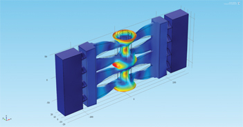
The acoustic–piezoelectric interaction analysis was conducted to find out the acoustic pressure distribution in the medium (mixture) to estimate the dynamic load influence on the resonance frequency. Acoustic pressure distribution in the cylinder with water is shown in Figure 8.

Acoustic pressure distribution in inner side of the cylinder with water on resonance.
Acoustic pressure of the PM system (Figure 2) inside the working hole is highest near the inlet and outlet of the cylinder as shown in Figure 8.
The distribution of the vibration amplitude of the four-star-shaped longitudinal converters joined to the one disk with gaps is shown in Figure 9. The high-intensity ultrasonic oscillation energy concentrated in a closed volume and intensive cavitation is created.

The distribution of vibration amplitude.
Acoustic pressure distribution in the cylinder with water is shown in Figure 10.

Acoustic pressure distribution in inner side of cylinder with water on resonance.
Moreover, Figures 7 and 9 show that the first longitudinal vibration mode of the converters transducers and the third bending mode of the hollow cylinder look like the matched cavity resonator.
The Experimental Results
For the experimental research the proposed PM systems shown in Figures 2 and 3 were made. The dimensions of the prototype systems were chosen from the results of the previous numerical analysis. The experimental research consists of two parts: electrical and mechanical displacement measurements of the systems and microscopic analysis of bioassay samples after algae cell ultrasonication.
Electromechanical System Measurements
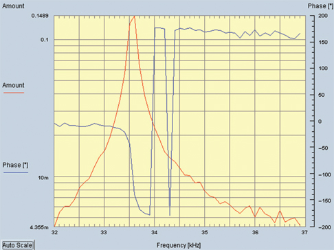
The gain–frequency characteristics of the proposed ultrasonic PM systems were measured by an impedance analyzer from the “Hesse & Knipps” company at 30% of maximum power. The empty and water-filled cylinders of the ultrasonic resonance system were defined as free and loaded systems respectively. In this paper we present only the admittance–frequency characteristics of systems loaded with water. Figures 11 and 12 show the admittance–frequency and phase characteristics for three-star-shaped and four-star-shaped disk-type PM systems, respectively.

Admittance–frequency and phase characteristics of three-star-shaped PM system.

Admittance–frequency and phase characteristics of four-star-shaped disk-type PM system.
We assume that the numerical and measured resonance frequency have a good agreement. The water damping reduced the resonance frequency and increased the phase characteristic distortion.
The mixture of water and algae, based on the numerical and experimental results, is a heavy load for the PM system and we should take this into consideration when designing electronic driver and control parts.
The mechanical amplitude–frequency and phase characteristics were measured by Doppler-laser vibrometer Polytec OFV-5000. It is difficult to change the position of the water-filled cylinder during laser measurement; therefore, the measurement results are shown only in the unloaded mode for systems shown in Figures 13 and 14 for systems presented in Figures 2 and 3, respectively.
Mechanical amplitude–frequency and phase characteristics of the three-star-shaped PM system.

Mechanical amplitude–frequency and phase characteristics of the four-star-shaped disk-type PM system.
Microscopic Analysis of Bioassay Samples
To confirm that proposed systems can operate successfully as algae cell wall destroyers, we carried out experiments with four kinds of algae cells. Using the methodology of the Hielscher Ultrasonics GmbH company (http://www.hielscher.com/ultrasonics/i1000_p.htm) the experimental setup for the three-star-shaped PM system is shown in Figure 15. The initial pressure of 2 bars was kept in the system during all tests. The ultrasonication process is variable from 1 to 3 min. The pump flow rate was 0.2 L/min. Algae volume is 1 L.
No Phase-Locked Loops (PLL) system is used. In current experiments the sweeping frequency mode is obtain.

The experimental setup diagram.
Four different species of algae: Chlorella sp., Pediastrum sp., Monoraphidium griffithii sp. and Kirchneriella sp. growing in Lithuanian lakes (Violeta Makarevičienė et al., 2011) were used in our experiments as bioassay samples.

Chlorella algae cells before (left) and after (right) ultrasonication.
In this paper the authors present biological test results only of proposed systems as shown in Figure 2. After a series of tests it was established that after ultrasonication about 54.3% of Chlorella sp. cells are completely destroyed (Figure 16).

Pediastrum simplex algae cells before (left) and after (right) ultrasonication.
The results of Pediastrum simplex algae cell before and after ultrasonication are shown in Figure 17. Colonies destroyed at about 70% and the cells destroyed at about 80%.

Monoraphidium griffithii algae cells before ultrasonication.
M. griffithii algae cell (Figure 18) after ultrasonication shows a very good result; about 93.5% cells are destroyed.
After ultrasonication about 88.9% of the Kirchneriella algae cells (Figure 19) are completely destroyed.

Kirchneriella algae cells before ultrasonication.
Conclusion
The compound PM ultrasonic systems can be implemented as a function of algae cell disruption. Instead of standard longitudinal PM systems for algae cell disruption we can use a different configuration of PM systems for creating high-intensity cavitation fields in closed volumes. Different kinds of species have a different cell wall protection level from microbubble implosion. We need to establish ultrasonication processes individually depending on the kind of species. During biological experiments we get very good results with three kinds of algae cells: Pediastrum simplex, M. griffithii and Kirchneriella and satisfactory results with Chlorella sp. cell.
The electronic frequency control driver for such compound systems should have special requirements because the mixture during ultrasonication processes is a very heavy dynamic load for ultrasonic PM systems. In our future work we plan to use the PLL system for resonance frequency tracking.
Funding statement: Funding: The work was supported by the Lithuanian Science Council project (No. MIP-018/2014).
References
Peshkovsky, S. , and A.Peshkovsky. 2007. Ultrasonic rod waveguide-radiator. Unites States patent No. US 7156201 B2, Jan. 2, 2007.Search in Google Scholar
Peshkovsky, S. , and A.Peshkovsky. 2007. “Matching a Transducer to Water at Cavitation – Acoustic Horn Design Principles.” Ultrasonics Sonochemistry14 (3):314–22.10.1016/j.ultsonch.2006.07.003Search in Google Scholar PubMed
Peshkovsky, S. , and A.Peshkovsky. 2010. High capacity ultrasonic reactor system. Unites States patent no. US 2010/0296975 A1, Feb. 18, 2014.Search in Google Scholar
Prohorenko, P. P. , N. V.Dezhkunov, and G. E.Konovalov. 1981. “Ultrasonic Capillary Effect.” Science and Technology P.1:135.Search in Google Scholar
Sieg, D. 2009. Making Algae Biodiesel at Home. 2012 edition, Paperback, August 30, 2011, ISBN-10: 1463733607.Search in Google Scholar
http://sonomechanics.com/technology/ultrasonic_horn_designs_and_properties/, Industrial Sonomechanics, LLC 479 W 146 Street, Ground Floor, New York, NY 10031, USA.Search in Google Scholar
Violeta Makarevičienė, V. , V.Andrulevičiūtė, V.Virginija Skorupskaitė, and J.Kasperovičienė. 2011. “Cultivation of Microalgae Chlorella sp. and Scenedesmus sp.as a Potentional Biofuel Feedstock.” Aplinkos Tyrimai, Inžinerija Ir Vadyba3 (57):21–7.Search in Google Scholar
http://www.hielscher.com/ultrasonics/i1000_p.htm, Hielscher Ultrasonics GmbH, Warthestrasse 21, D-14513 Teltow, Germany.Search in Google Scholar
©2015 by De Gruyter
Articles in the same Issue
- Frontmatter
- Editorial
- Temperature-Dependent Properties of a 1–3 Connectivity Piezoelectric Ceramic–Polymer Composite
- Co-firing of PZT–PMS–PZN/Ag Multilayer Actuator Prepared by Tape-Casting Method
- Compound Piezomechanical Systems of Algae Cell Disrupting
- Crystal Structures and Properties of Pb(Ni1/3,Nb2/3)O3–Pb(Zr1/2,Ti1/2)O3 Thin Films on Silicon Substrates
- Custom Lithium Niobate Transducer Arrays for Detecting Material Distribution of Hybrid Workpieces
- Design and Characterization of a Large Displacement Electro-thermal Actuator for a New Kind of Safety-and-Arming Device
- Effect of A-Site Ion Excess on (K, Na)NbO3 Thin Film Fabricated by Sol–Gel Non-alkoxide Process
- Effects of Ultrasonic Motor Stator Teeth Height on Start Reliability
- Epitaxial Growth and Multiferroic Properties of (001)-Oriented BiFeO3-YMnO3 Films
- Influences of Non-axial Process Loads on the Transducer and the Associated Mounting in Ultrasonic Machining
- Optimal Design of Cymbal Stack Transducer in a Piezoelectric Linear Actuator by Finite Element Method
- Optimization of a Piezoelectric Bending Actuator for a Tactile Virtual Reality Display
- Piezo Pump Disruptor for Algae Cell Wall Ultrasonication
- Piezoelectric Actuator Based on Two Bending-Type Langevin Transducers
- Process Emulation System for High-Power Piezoelectric Ultrasonic Actuators
- Properties of 0.96(Bi0.5Na0.5)TiO3-(0.04-x)BaTiO3-xLiNbO3 Lead-Free Piezoceramics Near Morphotropic Phase Boundary
- Modeling and Experimental Investigation of a Periodically Excited Hybrid Energy-Harvesting Generator