Characterization of the translational shear properties of the magnetorheological elastomers embedding the tilt chain-like structure
-
 ,
,
,
,

Abstract
In this study, the translational shear characteristics of the magnetorheological elastomers (MREs) with different chain-like structure angles (0°–90° with 15° increment) are tested and analyzed in detail. The experiments are performed under board ranges of strain amplitudes (1–20%), excitation frequencies (0.1–50 Hz), and magnetic fields (0–375 mT). The measured force-displacement data are utilized to analyze the role of chain-like structure angles on the viscoelastic properties together with their dependency on the excitation conditions, mass ratio of magnetic particles, and the magnetic field. The results illustrate that compared with the isotropic MREs and anisotropic MREs with symmetrical chain-like structures, the anisotropic MREs with the tilt chain-like structure can provide more significant variations in the average storage and loss moduli with a slight effect on the zero-field viscoelastic properties, and it exhibits higher frequency and strain dependencies. It can also suggest that the MREs with 30° chain-like structure have the largest MR effect. Besides, the mass ratio of the magnetic particles leads to an increase in the shear modulus of the MREs with the tilt chain-like structure. The test results can provide the fundamental characteristics of MREs for the application design.
1 Introduction
As a class of magnetorheological materials, magnetorheological elastomers (MREs) are a viscoelastic material that is made by embedding magnetic particles in a non-magnetic elastic matrix. After curing, the magnetic particles are immobilized within the elastic matrix, so compared with the magnetorheological fluids (MRFs), it can avoid the problem of particle sedimentation, and eliminate the need for seals which can reduce the effect of the seal friction on the operation process of the system [1,2,3]. The main operation modes of MREs are shear and squeeze modes [4,5], which have no flow mode compared to MRFs, because the viscoelastic properties of MREs cause them to lose the flow ability. Shear mode is one of the main working modes of MREs in practical applications. In an applied magnetic field, the interaction of the magnetic particles in the MREs causes a variation of its shear properties, such as storage modulus, loss modulus, loss angle, and so on. These tunable properties enable the shear-mode MREs to be utilized to develop various intelligent vibration adaptive devices, such as vibration absorbers [6,7,8] and vibration isolators [9,10,11]. The MRE-based adaptive devices demonstrate notably adjustable properties for the vibration system, including the natural frequency, vibration transmissibility, and so on.
In order to provide the fundamental characteristics of MREs for the application design, researchers have conducted a large number of studies on the testing and characterization of the shear properties of MREs [12]. The test results show that the tunable viscoelastic properties and magnetorheological (MR) effect are contingent upon a multitude of variables, including the excitation conditions (frequency and strain), magnetic field, type of magnetic particles, fabrication conditions (matrix material, additive type, magnetic particle mass ratio), and so on [13,14,15,16,17]. In addition, the magnetic anisotropy of the anisotropic MREs, which is caused by the chain-like arrangement of the magnetic particles, leads to a significant increase in the MR effect of MREs [18]. Furthermore, it has also been demonstrated that MREs with tilt chain-like structures exhibit enhanced MR effects in the shear mode [19]. Therefore, the arrangement of the magnetic particles with a proper angle may result in the optimal MR effect of MREs. Initially, the studies of the effect of the chain-like structure angle on the shear characteristics of MREs focused on the comparison between the isotropic MREs and the anisotropic MREs with the symmetrical chain-like structure angle (0° or 90°) [20]. Subsequently, the impact of the tilt chain-like structure angle ranging from 0° to 90° was explored operating on the rotational shear mode [21,22,23,24,25]. As far as we are aware in the valuable literature, the majority of test platforms for the tilt chain-like structure MREs are designed based on the rheometers with MR test function, which are performed in rotational shear mode [20,21,22,23,24,25]. A detailed investigation of translational shear properties of the tilt chain-like structure MREs is rarely reported [19,26]. Besides, the frequency and strain dependencies on the shear properties of the MREs with tilt chain-like structure angle have not been extensively investigated.
It should be noted that the rheometer test results are able to describe the shear characteristics of MREs in typical translational shear modes for isotropic MREs as well as MREs with chain-like structures perpendicular to the shear direction. This is due to the relatively central symmetric distribution of their magnetic particles. However, for the anisotropic MREs with a chain-like structure that is not perpendicular to the shear direction, the chain-like structure is no longer central symmetric. In the case of rotational shear excitation, the shear properties are found to be inconsistent at all positions. Besides, it is essential to apply a pre-normal force during the rheometer test to prevent slippage between the sample and the disks, which is a significant factor in the viscoelastic properties of MREs [27,28]. The pre-normal force is applied by the linear motor integrating with the rheometer equipment before the experiment. In particular, for the tilt chain-like structure MREs, the normal force may change the initial chain-like structure angle of the chain-like structure of MREs and then influence the accuracy of the test results. In addition, according to the arrangement forms of the shear-mode MREs used in the MREs-based vibration adaptive devices, it can be broadly categorized into the following types: multi-layer type [29], two-piece type [30], ring shape type [31], and torsional type [32]. Most of them operate in a linear (translational) motion, where the shear direction is reciprocated along a linear line [29,30,31,32]. Consequently, rheometer test results cannot be used to characterize the shear properties of MREs with a tilt chain-like structure in the typical linear shear mode of operation.
This study is aimed to characterize the shear-mode properties of the MREs with different tilt chain-like structure angles (0°–90° with 15° increment) based on the translational shear mode, which is identical to the typical linear shear mode of the MREs-based adaptive devices. The experiments are designed based on standardized test methods for rubber-like materials [33], which integrated a relatively compact electromagnet to realize the translational shear test, under board ranges of strain amplitude (1–20%), excitation frequency (0.1–50 Hz), and magnetic field (0–375 mT). The measured force-displacement data for the MREs specimens with different chain-like structure angles are analyzed to obtain the viscoelastic properties in terms of average storage modulus (G 1), loss modulus (G 2), and loss angle (δ). The role of chain structure angles on the viscoelastic properties and MR effect of MREs are discussed in detail. Meanwhile, the dependency of the excitation conditions and mass ratio of magnetic particles together with the applied magnetic field on the shear properties of MREs specimens with symmetrical chain-like structure angles and tilt chain-like structure angles is evaluated.
2 Experimental methods
2.1 MRE specimens
Several anisotropic MREs specimens are fabricated in the laboratory with different chain-like structure angles (0°–90° with 15° increment) and mass faction of carbonyl iron powders (CIPs) (30–70% with 20% increment), as shown in Table 1. In Table 1, MREs with 0° and 90° chain-like structure angles are defined as symmetrical chain-like structure, and the others are defined as tilt chain-like structure.
Main preparation parameters of MRE specimens
| MRE specimen | Chain structure angle (°) | Mass faction of CIPs (%) |
|---|---|---|
| Sample 1 | 0 | 50 |
| Sample 2 | 15 | 50 |
| Sample 3 | 30 | 50 |
| Sample 4 | 45 | 50 |
| Sample 5 | 60 | 50 |
| Sample 6 | 75 | 50 |
| Sample 7 | 90 | 50 |
| Sample 8 | 45 | 30 |
| Sample 10 | 45 | 70 |
| Sample 11 | Isotropic | 50 |
The spherical magnetically soft CIPs (SQ, BASF Inc., Germany), with a diameter varying from 3.9 to 5 μm are embedded inside a stretchable platinum-based silicone elastomer (Eco-Flex 00-20, Smooth-On Ine., USA) as the medium. The fabrication procedure is shown in Figure 1. In the beaker, the Components A and B of the silicone elastomer and CIPs are added and thoroughly blended using a mixer for around 3 min. The mixture is rest in a vacuum tank for around 3 min under a negative pressure of 29 mmHg, and then slowly poured into an aluminum mold. The mixture in the mold is cured for 3 h within a homogenous magnetic flux density of 500 mT (Sample 1–10), provided by an adjustable air gas magnet. As a control group, an isotropic MRE specimen with 50% mass faction of CIPs is cured for 3 h at room temperature (Sample 11). After demolding, the rectangular MREs specimens are obtained with dimensions of 20 × 20 × 5 mm, of which these dimensions are recommended in accordance with the current standards for shear testing of rubber-like materials (ISO 4664).
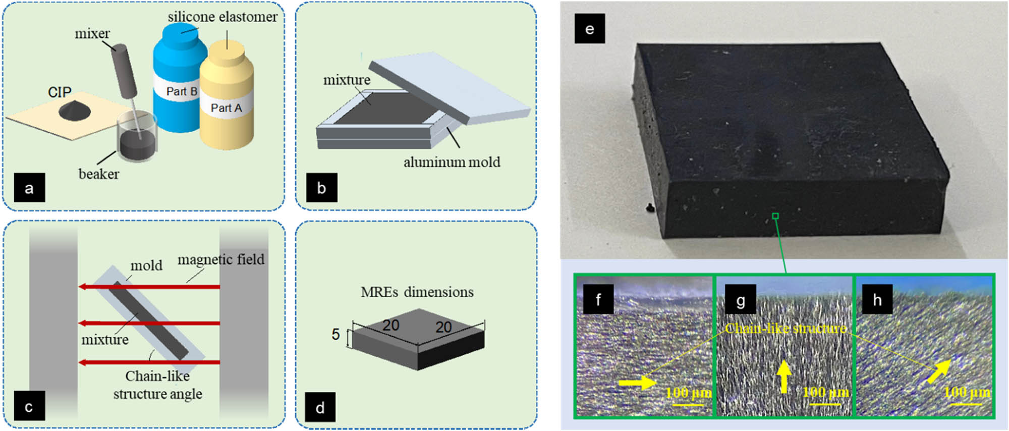
Preparation and characterization of MREs with different chain-like structure angles: (a) mixed materials; (b) schematic diagram of the MRE preparation mold; (c) schematic diagram of the curing process; (d) schematic diagram of the MREs’ dimensions; (e) photopic view of the MREs specimen; (f) microstructure diagram of the MREs with the chain-like structure parallel to the long side (Sample 7, Table 1); (g) microstructure diagram of the MREs with the chain-like structure perpendicular to the long side (Sample 1, Table 1); (h) microstructure diagram of the MRE with 45° chain-like structure angle (Sample 4, Table 1).
The arrangement of CIPs inside the anisotropic MREs is evaluated utilizing an engineering laser confocal microscope (BA600-4, Motic China Group Co., Ltd.). As shown in Figure 1(f)–(h), the homogeneous distribution of particles and the chain-like structure of particles in the medium can be clearly observed, and the preset arrangement angle is almost produced inside the MREs by the homogenous magnetic field during the curing procedure.
2.2 Electromagnet design
A test platform with the translational direction of movement is conducted to characterize the shear properties of MREs with chain-like structure angles under normal application conditions. An electromagnet is designed that can be integrated into a material dynamic mechanics testing system (ElectroForce 3200 Series) and permits the MREs specimens to be positioned within the air gaps. The electromagnet can be divided into an upper yoke, a lower yoke, two intermediate yokes (made of laminated cold-rolled grain-oriented electrical steel), and two copper conductor coils, as shown schematically in Figure 2(a). Two coils are inserted separately on two intermediate yokes. The two ends of the intermediate shaft are then fixed in the upper and lower yokes. The coils with 300 turns permitted airgap flux density in excess of 500 mT, when powered by a 6 V and 5 A power supply. The relationship between flux density and coil current is shown in Figure 2(b), which is measured by the Gauss meter. Two MREs specimens are installed within the air gaps of two upper beans respectively, and connected by the PLA chuck by the glue, which can prevent the slippage between the specimen and the machine. Due to asymmetric chain-like structure, the MREs specimens are to be arranged in two forms, as shown in Figure 2(c) and (d).
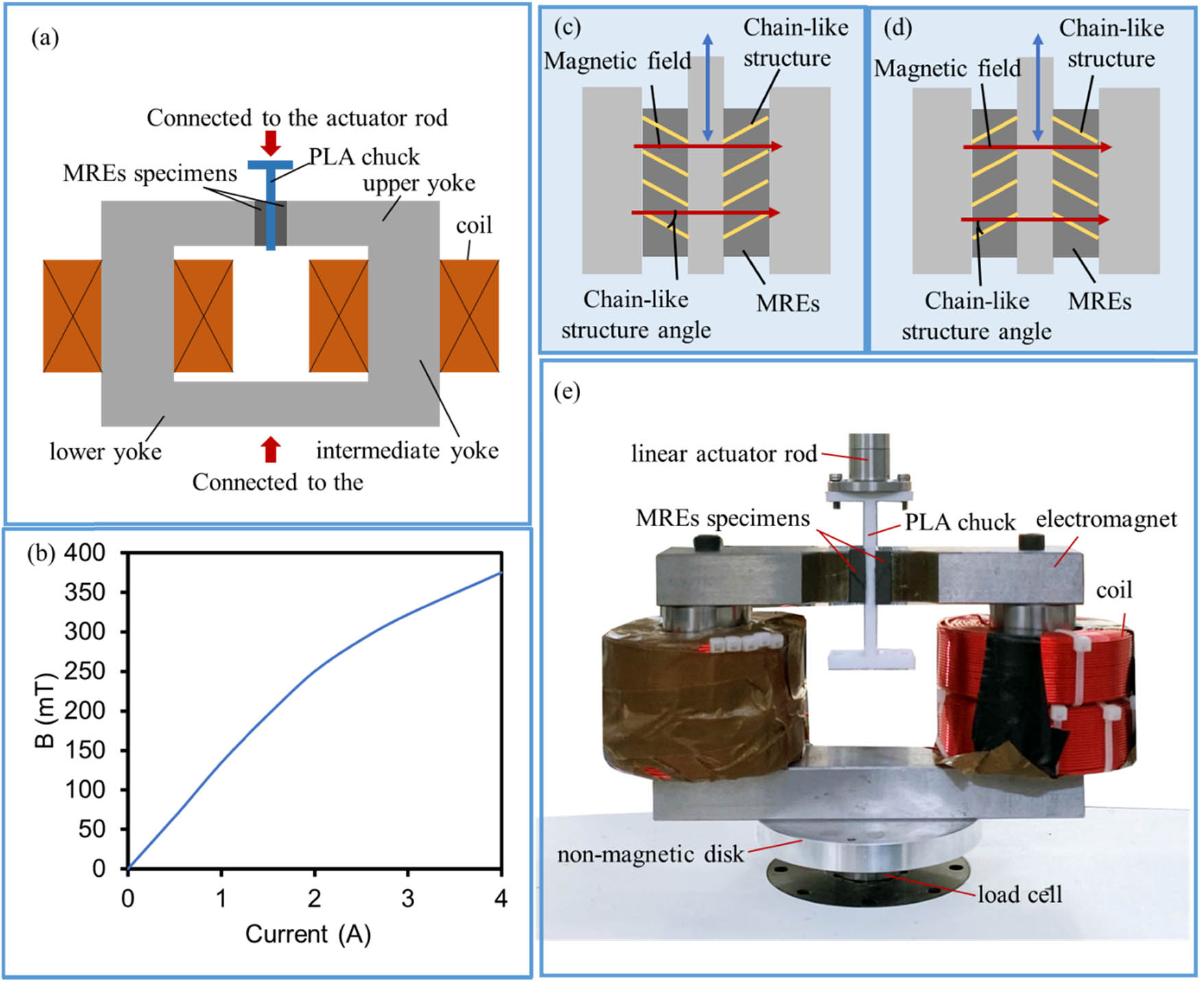
(a) Schematic diagram of the electromagnet design; (b) the relationship between the magnetic field density and input current of the designed electromagnet in the air gap; (c) arrangement form 1 of two pieces of MREs specimens; (d) arrangement form 2 of two pieces of MREs specimens; and (e) photopic of the experimental platform for the shear test of pre-structure MREs.
2.3 Experimental setup
The test platform together with the MREs specimens installed in the material dynamic mechanics testing system is shown in Figure 2(e). The bottom of the electromagnet is installed to a 50 N load cell of the material dynamic mechanics testing system through a non-magnetic disc to prevent the magnetic flux leakage from the magnetic core circuit. The top of the electromagnet is fixed to the rod of the linear electro-motor, which can provide 13 mm maximum displacement and 100 Hz maximum frequency. The material dynamic mechanics testing system is operated in the displacement feedback control mode. The shear displacement and force are measured by nanoscale grating scale (±6.5 mm, 0.05%FS) and load cell (±50 N, 0.05%Fs), and the measured data are recorded by the data acquisition software integrated with the material dynamic mechanics testing system. The sample rate is set at 200 points for one cycle homogeneous excitations. The cut-off frequency of the low-pass filter ranged from 10 to 2,000 Hz, depending on the loading frequency. The magnetic flux density is generated by a 300 W power supplier. The surface temperature of specimens is measured by the infrared thermometer (DECTMS520C, DELIXI ELECTRIC) before and after each experiment. A cooling fan is utilized to control the temperature of specimens at the range of 30° ± 5°C. Four series of experiments are designed to evaluate the shear characteristics of the MREs under translational motion direction, as shown in Table 2.
The experiment setup
| Experiment | Purpose | Specimens | Magnetic flux density (mT) | Strain amplitude (%) | Frequency (Hz) |
|---|---|---|---|---|---|
| Series 1 | Effect of the MREs arrangement forms and the magnetic flux density | Sample 1–7, 11 | 0–375 | 10 | 1 |
| Series 2 | Effect of strain amplitude | Sample 1, 3, 4, 7 | 0–250 | 1–20 | 1 |
| Series 3 | Effect of excitation frequency | Sample 1, 3, 4, 7 | 0–250 | 10 | 0.1–50 |
| Series 4 | Effect of mass faction of CIPs | Sample 4, 8, 10 | 0–250 | 10 | 1 |
3 Method of data analysis
Figure 3 shows a force–displacement loop obtained from the dynamic test on a double-piece shear test. It can be seen that the chain-like structure angle of the MREs specimens may cause the asymmetric and nonlinear characteristics of the force-displacement loop. As suggested by ISO-4664, when the force-displacement loop has some nonlinearity and the ellipse is not perfect, the suggested calculating method of the storage and loss modulus derived from the load–deflection curve will give an average value, which has been reported in several studies for the MRE testing [4,5,19,26,27]. Therefore, the recorded force-displacement data are employed to acquire viscoelastic properties of MREs, including the average storage (G 1) and loss (G 2) moduli in shear mode based on ISO-4664.

The identified parameter to characterize viscoelastic properties from the force–displacement loop.
For the double-piece shear test, the absolute complex shear modulus is given by equation (1):
where F 0 and x 0 are the maximum force and displacement amplitude, respectively; A and h are the cross-sectional area and thickness of the MRE specimens, respectively.
As suggested for rubbers in ref. [34], owing to the considerable nonlinearity in the measured force-displacement data, F 0 is represented by the average value of two peak values at the compression and extension strokes, as follows:
where F max and F min are the peak values of the compression and extension strokes, respectively.
The sine value of loss angle (δ) of the MRE specimens can be expressed as follows:
where A h is the area of the hysteresis loop, which can be derived as follows:
Therefore, the average storage and loss moduli of MREs specimens in the shear mode can be derived from the absolute complex shear modulus and loss angle, as follows:
The MR effect and relative MR effect coefficient can be expressed as follows:
where
4 Results and discussion
In the following sections, the viscoelastic properties of MREs including the average storage and loss moduli, loss factor as well as the relative MR effect calculated from the force-displacement data are analyzed to systematically investigate the impact of chain-like structure angle as well as the excitation conditions and fabrication parameters on the MREs embedding the tilt chain-like structure.
In order to verify the validation of the conducted experimental platform, an isotropic MRE in dick-shape with 50% mass faction of CIPs (diameter: 20 mm, thickness: 1 mm) is also prepared and tested by the rotational rheometer (Discover HR-2) under zero magnetic field. The storage and loss moduli obtained by the rotational rheometer are 28.1 and 7.66 kPa, while the average storage and loss moduli obtained by the proposed method are 26.9 and 8.1 kPa, respectively. The result shows good coherence and then the proposed method is used to investigate the viscoelastic properties of MREs including the average storage and loss moduli, loss factor as well as the relative MR effect.
4.1 Effect of the arrangement forms
Since the two MREs specimens can be arranged in two forms as shown in Figure 2(c) and (d), the effect of the arrangement form on the viscoelastic properties of the MREs is determined first. Figure 4 shows the force-displacement loop of the MRE with 45° chain-like structure under different conditions of magnetic field and arrangement forms. As shown in Figure 4, the force-displacement loop is asymmetric and shows an obvious shift with increase in applied magnetic field. The above phenomenon is related to the asymmetrically chain-like structure of the MREs, which produces the asymmetric magnetic torque of the MREs in the two shear directions under the magnetic field, as shown in Figure 4. The phenomenon can be expressed by the magnetic torque caused by the interaction of magnetized particles in the tilted chain-like structure, which attempts to rotate the chain-like structure to decrease the angle between the chain-like structure and the magnetic field, as shown in Figure 4.

The force-displacement loop of the MREs with 45° chain-like structure under different conditions of magnetic field and arrangement forms: (a) arrangement form 1 and (b) arrangement form 2.
To seek of simple expression, the following assumptions are made during the process of considering the magnetic torque between particles (
where μ 0 is the permeability of vacuum; m is the magnetic moment of each particle, which is always along the direction of the applied magnetic field (B), as the MREs component sample is based on the soft magnetic iron microparticles; and D represents the distance between adjacent particles.
Taking the installation method shown in Figure 2(c) (arrangement form 1) as an example, the two MREs specimens are mounted symmetrically with respect to the intermediate fixture. Under the applied magnetic field, the magnetized magnetic particles in the MREs interact with each other to produce a magnetic torque that makes the chain-like structure tend to be parallel to the direction of the magnetic field, as shown in Figure 4(a). The magnetic torque generated by the chain-like structure of the magnetic particles makes the MREs produce an upward force in the magnetic field on the intermediate fixture. This force generated by the magnetic interaction of the magnetic particles hinders the downward shear motion, and thus the stress acting in the MREs increases in the downward shear direction, which leads to the downward shift of the force–displacement curve, as shown in Figure 4(a). Similarly, after mounting the MREs using the arrangement form 2 as shown in Figure 2(d), the direction of the magnetic torque generated by the chain-like structure in the magnetic field is changed and the force acting in the intermediate fixture of the MREs is directed downwards, which leads to an upward shift of the force-displacement, as shown in Figure 4(b).
However, while the chain-like structure angles may result in the asymmetric stress-strain properties in the two directions related to the middle position, various total force is the same under the symmetric strain excitation for two arrangement forms. For example, the average storage modulus of MREs specimens with different chain-like structure angles and different arrangement forms is shown in Figure 5, where the simple harmonic test signal is 10% strain amplitude and 1 Hz excitation frequency (Series 1 shown in Table 2). As shown in Figure 5, there is only a slight difference in the value of the average storage modulus between the two arrangement forms. Therefore, in the following analysis, the average values between the test data of the two arrangements are taken as the shear modulus of each specimen.

G 1 of MREs specimens with different chain-like structure angles and arrangement forms.
4.2 Effect of the chain-like structure angle
The average storage and loss moduli of MREs specimens with different chain-like structure angles and the same mass ratio in different magnetic fields under a simple harmonic test signal with 10% strain amplitude and 1 Hz excitation frequency are shown in Figure 6 (Series 1 of Table 2). It should be noted that in the same ratio of MREs, the longer the length of the chain-like structure, the higher the magnetic torque produced by a single chain-like structure, due to the larger number of magnetic particles in the chain-like structure, as presented in equation (10). Therefore, the same ratio and size of MREs are used in this section to analyze the effect of the chain-like structure angle. It clearly shows that: (1) according to the increase of average storage and loss moduli with the enhanced magnetic field, all MREs specimens including the isotropic and anisotropic MREs can achieve significant MR effect; (2) compared with the isotropic MRE, the anisotropic MRE can provide more significant variations of the average storage modulus and loss modulus; (3) the chain-like structure angle results in the obvious difference of the average storage and loss moduli of MREs specimens; (4) except for the MREs specimen with 75° chain-like structure, the tilt chain structure angle arrangement can achieve more obvious variations of the average storage and loss moduli compared to symmetrical chain-like structure angle (0° and 90°).

Variation of MRE specimens in different magnetic fields: (a) G 1 and (b) G 2.
Figure 7 shows the relative MR effect of each MREs specimen calculated according to equations (8) and (9) at the magnetic field of 0–250 mT. As shown in Figure 7, the MR effects of the average storage and loss moduli of each MREs specimen are significantly different when the low magnetic field (≤250 mT) is applied to the electromagnet. In particular, the relative MR effect for the average storage modulus and loss modulus of the MREs specimen with 0° chain-like structure is about 4 and 5 times higher than that of the isotropic MREs specimen, as the magnetic field is varied from 0 to 135 mT. In addition, the experimental results show that MREs with tilt chain-like structure have the potential to provide higher MR effects. At 135 mT magnetic field, compared with the MREs with 0° chain-like structure (Sample 1), the relative MR effect of the average storage and loss modulus of MREs with 30° chain-like structure (Sample 3) increases by 51.1 and 70.3%, respectively. This means that MREs with tilt chain-like structure have a good potential for application, because it can achieve the same changes in MR effect at a lower power consumption.

The relative MR effect of MREs specimens at low currents: (a) G 1 and (b) G 2.
The relationship between the average storage and loss moduli of MREs and the chain-like structure angles is shown in Figure 8. From Figure 8(a) and (b), it can be observed that the average storage and loss moduli of each MREs specimen at zero field are similar, which means that the chain-like structure angle has only a small effect on the shear modulus of MREs at zero field. After energizing the electromagnet to apply a magnetic field to the MREs, the average storage and loss moduli of each MREs specimen increased. Under the effect of the applied magnetic field, the average storage and loss moduli of MREs show a tendency to increase and then decrease with the increase of the chain-like structure angle. It should be noted that the MREs specimen with 30° chain-like structure has the largest average storage modulus and loss modulus. Under the excitation of 10% strain amplitude and 1 Hz frequency at 375 mT magnetic field, the average storage modulus and loss modulus can reach 158.7 and 58.5 kPa, respectively. The relationships between the MR effects of the average storage and loss moduli of each MREs specimen and the chain-like structure angles are shown in Figure 8(c) and (d). Due to the similar zero-field modulus of each MRE specimen, the trend of its MR effect with the change of the chain structure angle is generally consistent with the trend of its shear modulus with the change of the chain-like structure angle. Compared with the anisotropic MREs with 0° chain-like structure, the arrangement of chain-like structures over the range of 15° to 45° can enhance the MR effect of the MREs under the same magnetic field, which shows the potential to improve the tunable viscoelastic performance of the MREs and then reduce their energy consumption.

Relationships between MREs shear properties and chain-like structure angle: (a) G 1, (b) G 2, (c) G 1-MR effect, and (d) G 2-MR effect.
It should be noted that it has been reported that the MREs with 45° chain-like structure achieves the greatest MR effect [22,24] subjected to the rheometer-based test. This discrepancy may be due to the fact that the angles between the shear direction and the chain-like structure are different at different regions during the rotational shear test. Taking 45° chain-like structure as an example (as shown in Figure 9), during the rotation testing procedure, there are several typical shear states exist in different regions of the chain-like structure sample. Therefore, the magnetorheological properties obtained from rotation test are the superposition of these shear states. The established linear shear test platform, in which all chain-like structures in all positions have the same operation mode (shear state), can provide a methodology to evaluate the influence of the chain-like structure angle on the magnetorheological properties of MREs.

The schematic of the shear states of the chain-like structure in different regions of the MREs with tilted chain-like structure under the rotational shear testing.
4.3 Effect of the excitation conditions
In order to investigate the influence of excitation conditions on the shear properties of MREs specimens with tilt chain-like structures, typical MREs specimens with 0°, 30°, 45°, and 90° chain-like structures are selected to analyze their shear properties under harmonic excitation signals of different frequencies and amplitudes. Among the four types of specimens, the MREs specimens with 0° and 90° chain-like structure angles have chain-like structures perpendicular/parallel to the shear direction (symmetrical chain-like structures), and the specimens with 30° and 45° chain-like structures are inclined to the shear direction. The experimental condition is shown in Series 2–3 of Table 2.
The relationships between average storage/loss modulus and excitation frequency for each MREs specimen under a harmonic excitation signal of 10% strain amplitude and different frequencies are shown in Figures 10 and 11. The excitation frequencies range from 0.1 to 50 Hz. From Figures 10 and 11, it can be seen that (1) the average storage modulus of each MREs specimen gradually increases with the increase in the excitation frequency and (2) the average loss modulus of each specimen shows a tendency to increase and then decrease with the increase in the excitation frequency. This is because that MREs, as an elastomer-based material, have a frequency dependence on material properties, which is referred to frequency hardening effect [36]. This phenomenon is related to the fact that as the strain rate increases, the rubber does not provide enough time to relax, resulting in greater variations in shear stress (shear force) for a given strain [37]. Besides, similar to the typical viscoelastic material, the MREs show a progression from rubbery–viscoelastic–glassy state with increasing excitation frequency [38]. At low frequencies, both the average storage and loss moduli increase with increasing excitation frequency. As the frequency continues to increase, the average storage modulus gradually stabilizes and the loss modulus peaks and then gradually decreases. Therefore, the tangent loss factor (tanδ) of the material shows a trend to increase and then decrease in this process. This phenomenon can also be found from the experimental data of the shear properties of the MREs with the tilt chain-like structure as shown in Figure 12.

The relationships between G 1 and excitation frequency for MREs with different chain-like structure angles: (a) 90°, (b) 45°, (c) 30°, and (d) 0°.

The relationships between G 2 and excitation frequency for MREs with different chain-like structure angles: (a) 90°, (b) 45°, (c) 30°, and (d) 0°.

Relationships of tangent loss factor and frequency for MREs specimens with 45° chain-like structure.
The comparisons of the MR effect of average storage and loss moduli between the MREs specimens with symmetrical chain-like structure (0° and 90°) and MREs specimens with tilt chain-like structure (30° and 45°) are illustrated in Figure 13. The applied magnetic field is 250 mT. It can be found from Figure 13 that the MREs specimens with tilt chain-like structure have the more obvious MR effect over the range of excitation frequencies (0.1–50 Hz). For example, the MREs specimens with 0° and 90° chain-like structures showed an increase of 54.2 and 26.2 kPa in average storage modulus, and an increase of 21.9 and 9.8 kPa in loss modulus, respectively, under the excitation signal of 10 Hz. Under the same conditions, the MRE specimens with 30° and 45° chain structure produced 87.0 and 71.5 kPa increase in average storage modulus and 46.5 and 36.5 kPa increase in loss modulus, respectively. The results also suggest that the MREs specimens with tilt chain-like structures have a higher frequency dependency compared to the MRE specimens with symmetrical chain-like structures. As an example, while the frequency ranges from 0.1 to 50 Hz, the MR effect of the average storage modulus of the MREs specimen with 30° chain-like structure changes from 81.2 to 96.5 kPa, increasing by 14.3 kPa, and the MR effect of loss modulus of it varies from 41.1 to 46.2 kPa, increasing by 5.1 kPa. In comparison, the MR effect of the average storage and loss moduli of the MREs specimen with 90° chain-like structure increases only by 7.5 and 3.9 kPa, respectively.

The MR effect of the MREs specimens with different chain-like structure angles under 250 mT applied magnetic field and different excitation frequencies (0.1–50 Hz): (1) G 1 and (2) G 2.
The relationship between the average storage/loss modulus and strain amplitude for each MREs specimen under a harmonic excitation signal at 1 Hz frequency and different strain amplitudes (1–20%) is shown in Figures 14 and 15. From Figures 14 and 15, it can be seen that (1) each MREs specimens have the highest shear modulus at 1% strain; (2) with the increase of strain amplitude, the average storage modulus and loss modulus of each MREs specimen show a significant decrease under different magnetic fields. This phenomenon can be explained as the strain softening effect (Payne effect) and caused by the more pronounced viscous flow due to the decomposition of the filler aggregates under the large strain excitations [39]. Besides, for MREs, the breaking of dipole–dipole interactions between neighboring particles as well as the detachment and recombination of filler rubbers also reduces the shear modulus at high strain amplitudes [40].

The relationships between G 1 and strain amplitude for MREs with different chain-like structure angles: (a) 90°, (b) 45°, (c) 30°, and (d) 0°.

The relationships between G 2 and strain amplitude for MREs with different chain-like structure angles: (a) 90°, (b) 45°, (c) 30°, and (d) 0°.
Figure 16 shows the MR effect of the MREs specimens under different strain amplitudes (1 to 20%) and 250 mT. As shown in Figure 16, in shear tests with strain amplitudes ranging from 1 to 20%, the MREs specimens with tilt chain-like structures show higher MR effects than the MRE specimens with chain-like structures symmetrical to the shear direction. For example, under the 1% strain amplitude conditions, the MREs specimens with 0° chain-like structures show an increase in average storage and loss moduli of 184.9 and 70.4 kPa for 10% strain amplitude excitation signals, respectively. Under the same conditions, the average storage and loss moduli increases are 378.4, 156.7, and 114.4 kPa produced by the MREs specimens with 30° chain-like structures, respectively. The results also suggest that the MREs specimens with tilt chain-like structures have higher strain dependency compared to MREs specimens with chain-like structures symmetrical to the shear direction with excitation strain ranging from 1 to 20%. As an example, while the strain ranges from 1 to 20%, the MR effect of the average storage modulus of the MREs specimen with 45° chain-like structure changes from 279.7 to 38.4 kPa, decreasing by 241.3 kPa, and the MR effect of loss modulus of it varies from 114.4 to 20.1 kPa, decreasing by 94.3 kPa. In comparison, the MR effect of the average storage and loss modulus of the MREs specimen with 0° chain-like structure decreases only by 144.2 and 29.7 kPa, respectively.

The MR effect of the MREs specimens with different structure angles under 250 mT applied magnetic field and different strain amplitudes (1–20%): (1) G 1 and (2) G 2.
4.4 Effect of the density of particles
MREs specimens with three mass ratios of 30, 50, and 70% with 45° chain-like structure are tested in a magnetic field ranging from 0 to 250 mT (Series 4 in Table 2), and their average storage modulus and loss modulus are shown in Figure 17. As shown in Figure 17, the average storage and loss moduli of MREs under zero field and in magnetic field show an increasing trend as the mass ratio of magnetic particles increases. For the MREs with tilt chain-like structure, under the same volume conditions, the increase in the mass ratio of the magnetic particles narrows the distance between the magnetic particles and then increases the magnetic moment generated by the magnetization of the magnetic particles, which in turn leads to an increase in the shear modulus of the MREs in the magnetic field. In summary, increasing the mass ratio of magnetic particles can significantly enhance the tunable shear properties of MREs, but too high mass ratio of magnetic particles can disrupt the structure of the matrix material and cause a decrease in the mechanical properties [41].

Effect of mass ratio of magnetic particle on shear modulus of MREs with 45° chain-like structure: (a) G 1 and (b) G 2.
5 Conclusion
In this study, the translational shear characteristics of the MREs with different chain-like structure angles (0°–90° with 15° increment) are tested and analyzed under board ranges of strain amplitudes (1–20%), excitation frequencies (0.1–50 Hz), and magnetic fields (0–375 mT). The test results show that: (1) compared with the isotropic MREs and anisotropic MREs with the symmetrical chain-like structures (0° and 90°), the anisotropic MREs with the tilt chain-like structure can provide more significant variations of the average storage modulus and loss modulus with a slight effect on the zero-field viscoelastic properties, especially under the low applied magnetic field density; (2) between 0° and 90° chain-like structure angles, the MREs specimen with 30° chain-like structure has the largest tunable range of average storage and loss modulus. Under the excitation of 10% strain amplitude and 1 Hz frequency at 375 mT magnetic field, the average storage and loss modulus can reach 158.7 and 58.5 kPa, respectively; (3) the MREs with tilt chain-like structures have more significant frequency and strain dependency compared to the MREs with symmetrical chain-like structures in the translational shear tests; (4) the mass ratio of the magnetic particles leads to an increase in the shear modulus of the MREs in the magnetic field.
Acknowledgment
The authors appreciate the full support from Xiamen TVS Test Science and Technology Co., Ltd.
-
Funding information: This research was supported by the National Natural Science Foundation of China (grant numbers: 52401379, 61733006, and U1813201) and the Natural Science Foundation of Fujian Province of China (grant number: 2022J01808).
-
Author contributions: Dezhao Lin: writing – original draft, methodology, investigation, formal analysis, data curation, and validation; Di Gong: writing – review and editing, conceptualization, methodology investigation, formal analysis, and data curation; Fan Yang: writing – review and editing, supervision, and funding acquisition; Ruihong Li: formal analysis, data curation, and validation; Weiqiang Zhang: formal analysis.
-
Conflict of interest: The authors declare that they have no known competing financial interests or personal relationships that could have appeared to influence the work reported in this paper.
-
Ethical approval: The conducted research is not related to either human or animal use.
-
Data availability statement: The datasets analyzed during the current study are available from the corresponding author on reasonable request.
References
[1] Ahamed R, Choi SB, Ferdaus MM. A state of art on magneto-rheological materials and their potential applications. J Intell Mater Syst Struct. 2018;29:2051–95. 10.1177/1045389X18754350.Suche in Google Scholar
[2] Bahl S, Nagar H, Singh I, Sehgal S. Smart materials types, properties and applications: A review. Mater Today: Proc. 2020;28:1302–6. 10.1016/j.matpr.2020.04.505.Suche in Google Scholar
[3] Rigbi Z, Jilken L. The response of an elastomer filled with soft ferrite to mechanical and magnetic influences. J Magn Magn Mater. 1983;37:267–76. 10.1016/0304-8853(83)90055-0.Suche in Google Scholar
[4] Dargahi A, Sedaghati R, Rakheja S. On the properties of magnetorheological elastomers in shear mode: Design, fabrication and characterization. Compos Part B: Eng. 2019;159:269–83. 10.1016/j.compositesb.2018.09.080.Suche in Google Scholar
[5] Vatandoost H, Hemmatian M, Sedaghati R, Rakheja S. Dynamic characterization of isotropic and anisotropic magnetorheological elastomers in the oscillatory squeeze mode superimposed on large static pre-strain. Compos Part B: Eng. 2020;182:107648. 10.1016/j.compositesb.2019.107648.Suche in Google Scholar
[6] Xie Y, Fu J, Zhu M, Qi S, Tian R, Yu M. A magnetorheological vibration absorber with bidirectional tunability for pipelines. Smart Mater Struct. 2023;32:125007. 10.1088/1361-665X/ad00f2.Suche in Google Scholar
[7] Zhu Z, Wang Z, Dai K, Wang X, Zhang H, Zhang W. An adaptive and space-energy efficiency vibration absorber system using a self-sensing and tunable magnetorheological elastomer. Nano Energy. 2023;117:108927. 10.1016/j.nanoen.2023.108927.Suche in Google Scholar
[8] Zhao W, Li B, Tian W, Liu P, Liao W. Magnetorheological elastomer absorber-based chatter suppression in robotic milling. Robot Computer-Integr Manuf. 2024;88:102740. 10.1016/j.rcim.2024.102740.Suche in Google Scholar
[9] Niu C, Dong X, Xiong X, Ren J, Niu L, Li C, et al. Development of an electrorheological elastomer isolator working in shear-squeeze mixed mode. Smart Mater Struct. 2023;32:065004. 10.1088/1361-665X/accda5.Suche in Google Scholar
[10] Wang Q, Chen Z, Wang Y, Gong N, Yang J, Li W, et al. A metamaterial isolator with tunable low frequency stop-band based on magnetorheological elastomer and magnet spring. Mech Syst Signal Process. 2024;208:111029. 10.1016/j.ymssp.2023.111029.Suche in Google Scholar
[11] Lin D, Yang F, Gong D, Li R. A new vibration isolator integrating tunable stiffness-damping and active driving properties based on radial-chains magnetorheological elastomer. Mech Syst Signal Process. 2023;183:109633. 10.1016/j.ymssp.2022.109633.Suche in Google Scholar
[12] Bastola AK, Hossain M. A review on magneto-mechanical characterizations of magnetorheological elastomers. Compos Part B: Eng. 2020;200:108348. 10.1016/j.compositesb.2020.108348.Suche in Google Scholar
[13] Nam TH, Petríková I, Marvalová B. Effects of loading rate, applied shear strain, and magnetic field on stress relaxation behavior of anisotropic magnetorheological elastomer. Mech Adv Mater Struct. 2022;29:2984–98. 10.1080/15376494.2021.1883162.Suche in Google Scholar
[14] Nedjar A, Aguib S, Djedid T, Nour A, Meloussi M. Measurements and identification of smart magnetomechanical elastomer composite materials properties in shear mode. Mater Res Express. 2019;6:085707. 10.1088/2053-1591/ab201b.Suche in Google Scholar
[15] Hemmatian M, Sedaghati R, Rakheja S. Characterization and modeling of temperature effect on the shear mode properties of magnetorheological elastomers. Smart Mater Struct. 2020;29:115001. 10.1088/1361-665X/abb359.Suche in Google Scholar
[16] Burgaz E, Goksuzoglu M. Effects of magnetic particles and carbon black on structure and properties of magnetorheological elastomers. Polym Test. 2020;81:106233. 10.1016/j.polymertesting.2019.106233.Suche in Google Scholar
[17] Nam TH, Petríková I, Marvalová B. Experimental and numerical research of stress relaxation behavior of magnetorheological elastomer. Polym Test. 2021;93:106886. 10.1016/j.polymertesting.2020.106886.Suche in Google Scholar
[18] Tian TF, Li WH, Alici G, Du H, Deng YM. Microstructure and magnetorheology of graphite-based MR elastomers. Rheol Acta. 2011;50:825–36. 10.1007/s00397-011-0567-9.Suche in Google Scholar
[19] Tian T, Nakano M. Fabrication and characterisation of anisotropic magnetorheological elastomer with 45° iron particle alignment at various silicone oil concentrations. J Intell Mater Syst Struct. 2018;29:151–9. 10.1177/1045389X17704071.Suche in Google Scholar
[20] Boczkowska A, Awietjan SF, Wroblewski R. Microstructure–property relationships of urethane magnetorheological elastomers. Smart Mater Struct. 2007;16:1924. 10.1088/0964-1726/16/5/049.Suche in Google Scholar
[21] Kobzili L, Aguib S, Chikh N, Djedid T, Meloussi M. Modeling and simulation of the static and vibratory behavior of hybrid composite plate off-axis anisotropic. Compos Struct. 2021;273:114297. 10.1016/j.compstruct.2021.114297.Suche in Google Scholar
[22] Sulatchaneenopdon N, Son HW, Khantachawana A, Garcia-Barruetabena J, Elejabarrieta MJ, Takahashi T, et al. Influence of pre-structure orientation on the linear viscoelastic limit of magnetorheological elastomers. J Intell Mater Syst Struct. 2023;34:89–100. 10.1177/1045389X221094304.Suche in Google Scholar
[23] Boczkowska A, Awietjan SF, Pietrzko S, Kurzydłowski KJ. Mechanical properties of magnetorheological elastomers under shear deformation. Compos Part B: Eng. 2012;43:636–40. 10.1016/j.compositesb.2011.08.026.Suche in Google Scholar
[24] Yao J, Yang W, Gao Y, Scarpa F, Li Y. Magnetorheological elastomers with particle chain orientation: modelling and experiments. Smart Mater Struct. 2019;28:095008. 10.1088/1361-665X/ab2e21.Suche in Google Scholar
[25] Zhang J, Pang H, Wang Y, Gong X. The magneto-mechanical properties of off-axis anisotropic magnetorheological elastomers. Compos Sci Technol. 2020;191:108079. 10.1016/j.compscitech.2020.108079.Suche in Google Scholar
[26] Nguyen XB, Komatsuzaki T, Truong HT. Properties of inhomogeneous-type magnetorheological elastomer formed in the presence of a magnetic field with tilted angles. J Magn Magn Mater. 2023;584:171065. 10.1016/j.jmmm.2023.171065.Suche in Google Scholar
[27] Vatandoost H, Sedaghati R, Rakheja S, Hemmatian M. Effect of pre-strain on compression mode properties of magnetorheological elastomers. Polym Test. 2021;93:106888. 10.1016/j.polymertesting.2020.106888.Suche in Google Scholar
[28] Mazlum U, Celik I. Determination of shear behavior of magneto-rheological elastomers under harmonic loading. J Elastomers Plast. 2023;55:361–82. 10.1177/00952443221147638.Suche in Google Scholar
[29] Zhu M, Fu J, Li W, Xia D, Qi S, Yu M. Design and co-optimization of a laminated isolation bearing based on magnetorheological elastomer. Mech Syst Signal Process. 2021;159:107843. 10.1016/j.ymssp.2021.107843.Suche in Google Scholar
[30] Susheelkumar GN, Murigendrappa SM, Gangadharan KV. Theoretical and experimental investigation of model-free adaptive fuzzy sliding mode control for MRE based adaptive tuned vibration absorber. Smart Mater Struct. 2019;28:045017. 10.1088/1361-665X/ab04b6.Suche in Google Scholar
[31] Jalali A, Dianati H, Norouzi M, Vatandoost H, Ghatee M. A novel bi-directional shear mode magneto-rheological elastomer vibration isolator. J Intell Mater Syst Struct. 2020;31:2002–19. 10.1177/1045389X20942314.Suche in Google Scholar
[32] Gao P, Liu H, Xiang C, Yan P, Mahmoud T. A new magnetorheological elastomer torsional vibration absorber: structural design and performance test. Mech Sci. 2021;12:321–32. 10.5194/ms-12-321-2021.Suche in Google Scholar
[33] Rubber, vulcanized or thermoplastic — Determination of dynamic properties. 2022, ISO4664:2022.Suche in Google Scholar
[34] Brown R. Physical testing of rubber. Springer US: Springer Science & Business Media; 2006.10.1007/0-387-29012-5Suche in Google Scholar
[35] Kim J, Chung SE, Choi SE, Lee H, Kim J, Kwon S. Programming magnetic anisotropy in polymeric microactuators. Nat Mater. 2011;10:747–52. 10.1038/NMAT3090.Suche in Google Scholar PubMed
[36] Khanouki MA, Sedaghati R, Hemmatian M. Experimental characterization and microscale modeling of isotropic and anisotropic magnetorheological elastomers. Compos Part B: Eng. 2019;176:107311. 10.1016/j.compositesb.2019.107311.Suche in Google Scholar
[37] Vatandoost H, Norouzi M, Alehashem SMS, Smoukov SK. A novel phenomenological model for dynamic behavior of magnetorheological elastomers in tension–compression mode. Smart Mater Struct. 2017;26:065011. 10.1088/1361-665X/aa6126.Suche in Google Scholar
[38] Dargahi A. Fabrication, characterization and modeling of magnetorheological elastomers. Quebec: Concordia University; 2017.Suche in Google Scholar
[39] Leblanc JL. Rubber–filler interactions and rheological properties in filled compounds. Prog Polym Sci. 2002;27:627–87. 10.1016/S0079-6700(01)00040-5.Suche in Google Scholar
[40] Rendek M, Lion A. Amplitude dependence of filler-reinforced rubber: Experiments, constitutive modelling and FEM–Implementation. Int J Solids Struct. 2010;47:2918–36. 10.1016/j.ijsolstr.2010.06.021.Suche in Google Scholar
[41] Ubaidillah S, Sutrisno J, Purwanto A, Mazlan AS. Recent progress on magnetorheological solids: Materials, fabrication, testing, and applications. Adv Eng Mater. 2015;17:563–97. 10.1002/adem.201400258.Suche in Google Scholar
© 2024 the author(s), published by De Gruyter
This work is licensed under the Creative Commons Attribution 4.0 International License.
Artikel in diesem Heft
- Research Articles
- Bearing behavior of pile foundation in karst region: Physical model test and finite element analysis
- Study on precursor information and disaster mechanism of sudden change of seepage in mining rock mass
- Viscosity model based on Giesekus equation
- Two-dimensional rheo-optical measurement system to study dynamics and structure of complex fluids
- Assessment of heat transfer capabilities of some known nanofluids under turbulent flow conditions in a five-turn spiral pipe flow
- Cubic autocatalysis implementation in blood for non-Newtonian tetra hybrid nanofluid model through bounded artery
- Ramification of Hall effects in a non-Newtonian model past an inclined microchannel with slip and convective boundary conditions
- Computational analysis of nanoparticles and waste discharge concentration past a rotating sphere with Lorentz forces
- Viscoplastic fluid flow in pipes: A rheological study using in-situ laser Doppler velocimetry
- Prediction of sensory textures of cosmetics using large amplitude oscillatory shear and extensional rheology
- Effect of bell plate structure on high- and low-frequency characteristics of hydraulic mount
- Computational role of the heat transfer phenomenon in the reactive dynamics of catalytic nanolubricant flow past a horizontal microchannel
- Exploring concentration-dependent transport properties on an unsteady Riga plate by incorporating thermal radiation with activation energy and gyrotactic microorganisms
- Calendering of non-isothermal viscoelastic sheets of finite thickness: A theoretical study
- Electromagnetic control and heat transfer enhancement in exothermic reactions experiencing current density: The study preventing thermal explosions in reactive flow
- Characterization of the translational shear properties of the magnetorheological elastomers embedding the tilt chain-like structure
- Low-cost rolling ball viscometer for the evaluation of Newtonian and shear-thinning fluids
- Impact of calcination temperature, organic additive percentages, and testing temperature on the rheological behaviour of dried sewage sludge
- Rheo-NMR velocimetry of nanocrystalline cellulose suspensions
- Review Articles
- Master curves construction for viscoelastic functions of bituminous materials
- Electrorheological characterization of complex fluids used in electrohydrodynamic processes: Technical issues and challenges
- Corrigendum
- Corrigendum to: “The ductility performance of concrete using glass fiber mesh in beam specimens”
- Special Issue on The rheological test, modeling and numerical simulation of rock material - Part I
- Study on the evolution of permeability properties of limestone under different stress paths
- Shale hydraulic fracture morphology and inter-well interference rule under multi-wellbore test
- Investigation and numerical simulation study on the vertical bearing mechanism of large-diameter overlength piles in water-enriched soft soil areas
- Evolution characteristics of calcareous sand force chain based on particle breakage
- Structural damage characteristics and mechanism of granite residual soil
- Rheological characteristics and seepage laws of sandstone specimens containing an inclined single fracture under three-dimensional stress