
Perspective on advanced nanomaterials used for energy storage and conversion
-
Hsuanyi Huang


Abstract
To drive the next ‘technical revolution’ towards commercialization, we must develop sustainable energy materials, procedures, and technologies. The demand for electrical energy is unlikely to diminish over the next 50 years, and how different countries engage in these challenges will shape future discourse. This perspective summarizes the technical aspects of nanomaterials’ design, evaluation, and uses. The applications include solid oxide fuel cells (SOFCs), solid oxide electrolysis cells (SOEC), microbial fuel cells (MFC), supercapacitors, and hydrogen evolution catalysts. This paper also described energy carriers such as ammonia which can be produced electrochemically using SOEC under ambient pressure and high temperature. The rise of electric vehicles has necessitated some form of onboard storage of fuel or charge. The fuels can be generated using an electrolyzer to convert water to hydrogen or nitrogen and steam to ammonia. The charge can be stored using a symmetrical supercapacitor composed of tertiary metal oxides with self-regulating properties to provide high energy and power density. A novel metal boride system was constructed to absorb microwave radiation under harsh conditions to enhance communication systems. These resources can lower the demand for petroleum carbon in portable power devices or replace higher fossil carbon in stationary power units. To improve the energy conversion and storage efficiency, we systematically optimized synthesis variables of nanomaterials using artificial neural network approaches. The structural characterization and electrochemical performance of the energy materials and devices provide guidelines to control new structures and related properties. Systemic study on energy materials and technology provides a feasible transition from traditional to sustainable energy platforms. This perspective mainly covers the area of green chemistry, evaluation, and applications of nanomaterials generated in our laboratory with brief literature comparison where appropriate. The conceptual and experimental innovations outlined in this perspective are neither complete nor authoritative but a snapshot of selecting technologies that can generate green power using nanomaterials.
Introduction
Nanotechnology is intrinsically multidisciplinary, including the design of functional structures with dimensions measured in nanometer (nm) in at least one dimension [1]. These nanomaterials and device systems can be engineered to exhibit novel physical, chemical, electronic, magnetic, and biological properties. The unique phenomena and processes are due to the limited size of the constituent particles or clusters [2, 3]. From the size perspective, nanotechnology focuses on understanding and controlling the materials ranging from 1 to 100 nm, at least in one dimension [4]. Research data indicated that the unique phenomena of nanomaterials enable their novel applications, and this perspective presented our discoveries on energy storage and conversion. According to the end demands, these nanomaterials with tunable properties can be used in catalysis, sustainable energy, consumer products, and electronics [5, 6]. It is critical to maintain the stability of interfaces between nanoparticles and integrate these “nanostructures” at micron-length and macroscopic scales [7, 8]. The most important changes in the behavior and activities of nanomaterials mainly result from their intrinsic nature instead of a sole reduction in size [9]. These observations include size confinement, a predominance of interfacial phenomena, and quantum mechanics correlated with electron configurations and orbital diagrams [10]. When the feature and size of nanomaterials can be controlled and tuned, their properties and reactivities can be enhanced according to their unique functions [11], [12], [13].
Research discoveries on molecular self-assembly depict that nanotechnological research opens a new paradigm to explore novel materials at nano-dimension with controllable atomic size, beyond traditional thermodynamics [14]. These concerns have led to a debate among advocacy groups and governments on whether special regulation of nanotechnology is warranted [15]. Over two decades, Dr. Liu and her collaborators designed and produced six different categories of materials, namely perovskite-based ceramics, noble and transition metals, metal oxides and their composites, metal and metal oxide composites, metal-organic frameworks, polymeric membranes, and carbon supported catalysts. Recently, she and Dr. Zhen collectively explored a new family of materials, metal boride. This family of materials was found to be applicable to absorb microwaves and highly resistant to harsh environments. We will begin with sol-gel and solvothermal synthesis, which have the advantages of speed, simplicity, and application to several narrow- and wide-band semiconductor-based photo- and electrocatalysts. We will demonstrate that the addition of reduced graphene oxide as a scaffold and current collector can yield catalytic advantages that are not present with sol-gel nanoparticle systems. We will then describe the ball milling (OBMA) approach that has the advantage of mechanical sieving of the catalyst with rough surfaces for electron/whole generation and their characterization. Morphological examination of materials by scanning and transmission electron microscopy, X-ray powder diffraction, and crystallography. The cyclic voltammetry and electrochemical impedance spectroscopies were applied to measure energy devices’ current and power densities, capacitance, and cycle stability. We will also highlight an important consideration between electrocatalytic performance at the catalyst and device levels, which the investigator must be mindful of to gain the most optimal catalyticity. We pay attention to energy storage or production systems, beginning with solid oxide fuel cells (SOFCs) to generate energy for stationary power applications. In these SOFCs, redox reactions convert chemical reactants into electricity using efficient perovskite ORR catalyst. As is well-known, the N≡N is almost 950 kJ mol−1 and is dissociated by coupling the energy output from a SOFC as an input into a solid oxide electrolysis cell (SOEC). A microbial fuel cell would be appropriate for low power output if chemical energy is required at ambient temperatures. We demonstrate graphene current collector to transport redox chemistries in many electrogenic microorganisms as a more efficient channel than redox mediators. Furthermore, a supercapacitor is an attractive option if fast start-up times are required in a unit (generator or electric engine) to receive the stored potential energy for device start-up. The electrons can be discharged quickly in contrast to a battery, where the potential energy is stored in chemical energy and discharged slowly at a constant voltage. Much of these chemistries are done at higher temperatures to promote faster kinetics and are designed using known physical principles. Microorganism, through evolution, can do similar chemistries, albeit at slower rates but ambient conditions. The role of artificial hydrogenases was studied in the generation of another energy carrier, hydrogen. The advantages include less carbon emission in comparison with coal-based hydrogen generation. The ideal combinations of energy resources should include various devices that can generate constant voltage, have high energy storage capacity, and have fast output. The different systems include solid oxide fuel cells, solid oxide electrolysis cells, proton exchange membrane fuel cells, microbial fuel cells, supercapacitor, cancer theranostics, and water remediation. In this perspective, these materials’ design, evaluation, and different applications (Fig. 1) will be discussed and compared with other research findings.
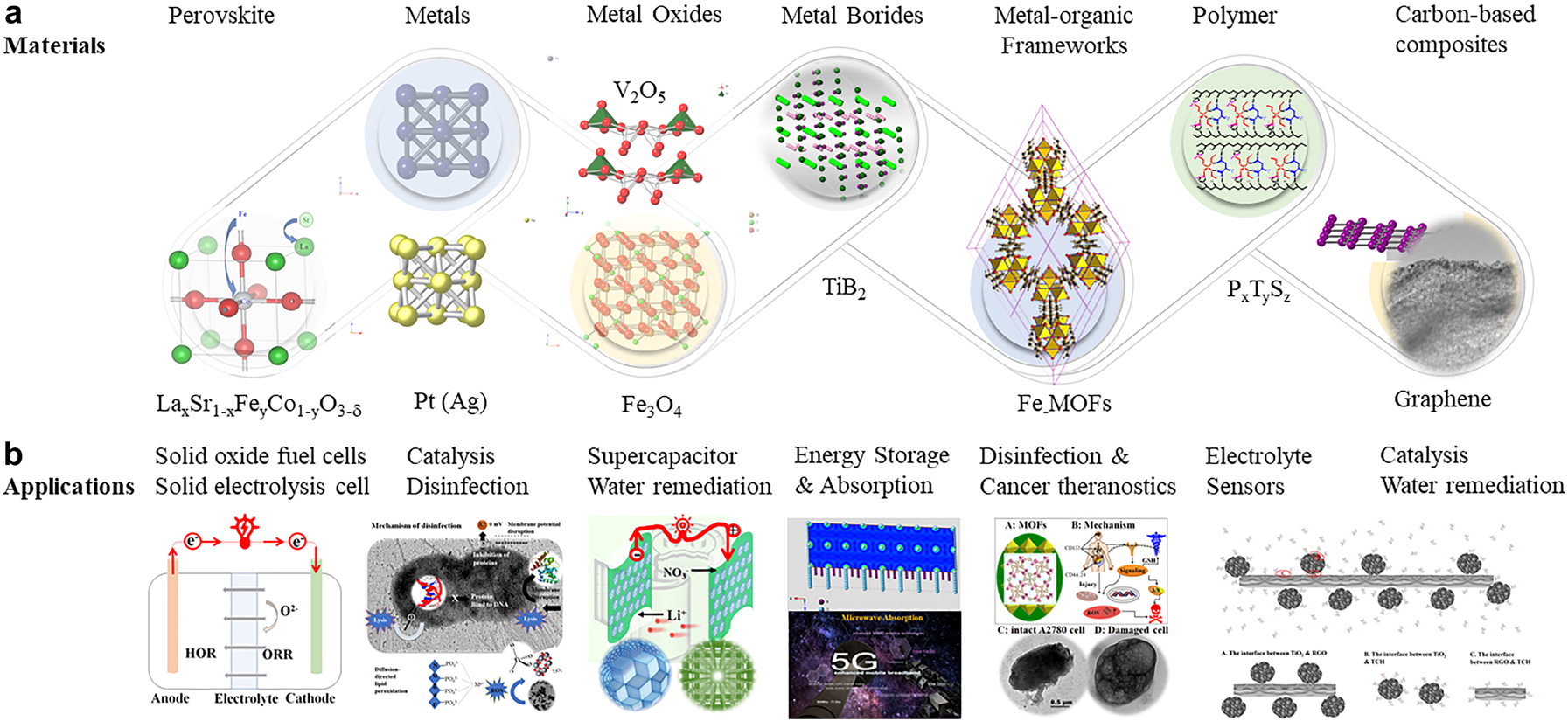
The nanomaterials and their application, (a): Nanomaterials produced in Liu’s laboratory and their structures (top panel), (b): Application of energy nanomaterials (bottom panel).
Design and evaluation of nanomaterials
Synthesis of nanomaterials
The bottom-up and top-down synthesis methods have been widely used to prepare a series of nanostructured materials. The composite materials were used as demonstrations due to a combination of wet-chemistry and solid-state chemistry. The polyvinylpyrrolidone (PVP)-templated TiO2 anatase powders were prepared by a sol-gel method and then coordinated with reduced graphene oxides (rGO) by ultraviolet radiation. The titania is used as the photocatalyst and the PVP as a porogen to control pore size. The rGO acts as the electron conductor and aligns the photocatalyst along one axial plane of the graphene. The PVP templated TiO2 was consequently subject to heat-treatment at 400 °C to form crystallized TiO2 and decompose the porogen. The GO-TiO2 composite was treated under UV radiation to obtain rGO-TiO2 [16]. The aim was to align the p z orbitals of graphene with the d orbitals of Ti to facilitate the electron transfer and extend the charge carriers’ lifespan. It was found that our approach successfully controlled the composite structure, hydrolysis inhibition, mesoporous templating, crystallization, and reduction, as shown in Fig. 2. It was found that the citric acid as a tri-topic ligand enables the formation of a coordinative complex between the Ti and carboxylic groups to successfully prevent the hydrolysis of Ti(OnBu)4 (in Fig. 2a). The d 0 configuration of Ti element in [Ti(OH)4]2− anion in a dimer was demonstrated, indicating that the Ti bidentate complex prevented the growth of sub-building units. The planar bipyramidal structure with citrate located in the equatorial position was formed. During the condensation/polymerization phase of the Ti-containing precursor, the polymer polyvinylpyrrolidone K30 (PVP-K30, Fig. 2b) was used to generate uniform pore diameters and particle sizes due to its inherent properties, such as pyrrolidone ring, high polarity, cohesivity, and resultant propensity. The ion-dipole between Ti from titanium alkoxide and O from the PVP template can be formed. As a result, the TiO2 particles can be anchored along the PVP chain from the molecular level. The continuous lattice, such as Ti-O-Ti or Ti-H-Ti, was formed to create an oxide matrix through poly-condensation responses of a sub-atomic precedent (Fig. 2c and Fig. S1) [17].
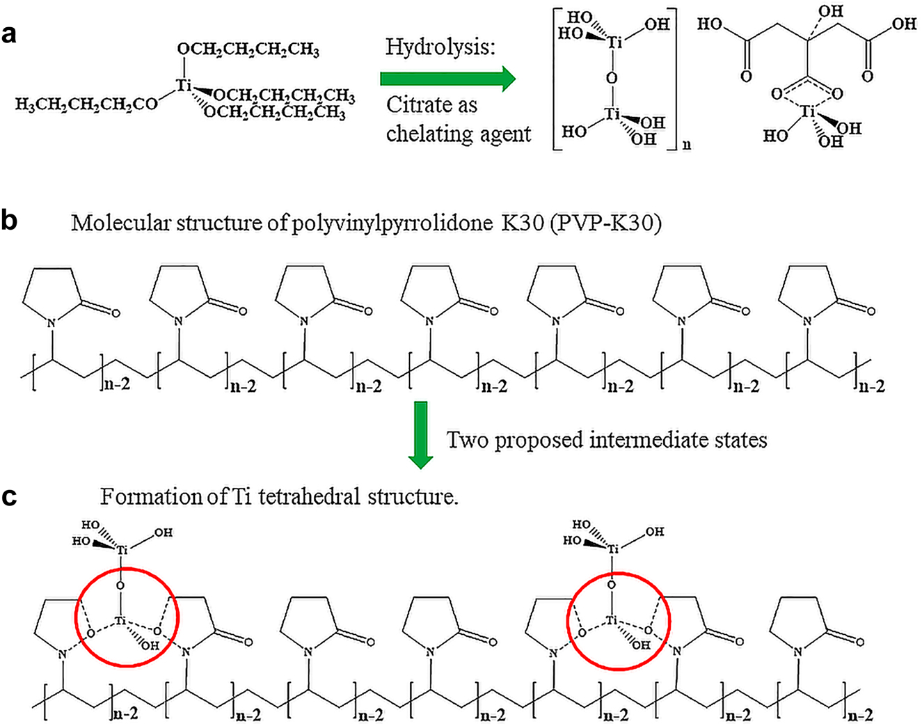
The preparation of rGO-TiO2 composites, using a scalable sol-gel method, followed by a calcination and UV reduction, (a): Sol-gel synthesis to form TiO6 polymeric network; (b): Templation to facilitate the mesoporous structure; (c): Crystallization to form anatase photocatalyst (also see Supplemental Figs. S1–S3).
Through controlled stoichiometry, different amounts of the PVP-K30 were introduced to tune the pore structures. With further drying and heat treatment, the above “wet-gel” was converted into anatase TiO2 polycrystals, showing the d-orbital of Ti splitting (Fig. S2). Based on the crystal field theory, the five d-orbitals of the Ti atom were subject to the energy increase when Ti was coordinatively bonded with bonding atoms, such as oxygen. It was anticipated that a rapid conversion from tetrahedral to octahedral thermal units due to the decrease in splitting energy, resulting in anatase crystalline phases upon heat-treatment. The last step was the reduction of graphene oxide (GO) under ultraviolet, as demonstrated in our previous publication [7]. The Hummer method derived graphene oxide was an ideal candidate for incorporation into the PVP-templated TiO2 matrix. It was found that the graphene substrate allows for anchoring PVP-templated TiO2 through chemical bonding (Fig. S3A). The heat-treatment initiated anatase TiO2 formation (Fig. S3B) along the graphene oxide surfaces. Following the UV radiation, the graphene oxide was reduced (Fig. S3C) to remove a controlled number of functional groups and impurities. During this processing, the conversion from sp 3 to sp 2 hybridization of carbon atoms occurred and resulted in the formation of hybrid materials with tuneable surface texture and composition. The steric hindrance of citric acid and cohesivity of PVP-K30 prevented the TiO2 crystal growth at high temperatures, such as 400 °C. The homogeneity and architecture of rGO-supported TiO2 nanocatalyst can be tuned, enabling photo receptivity to shift from UV alone to visible light (VL) region. This is due to orbital overlap between p z orbital of rGO and d-orbitals of TiO2 to lower than bandgap and allow VL energies to be used to generate O2−/h vacancies on the rGO-TiO2 surface for more efficient catalysis. Multiscale texturation and scaling production can be achieved by combining sol-gel chemistry and heat-treatment, followed by a post-reduction thermal-dynamically [18].
Characterization of nanomaterials
The nanomaterials have been characterized using spectroscopy, electron microscopy, X-ray diffraction, and X-ray photoelectron spectroscopy approaches to determine the crystalline structure, crystallite size, morphology, and oxidation states. The X-ray photoelectron spectroscopy (XPS, Omicron XPS/UPS), UV–Vis adsorption (Shimadzu UV-1601PC), Bruker D8 advance powdered X-ray diffraction (XRD), Tecnai F20 G2 transmission electron microscopy equipped with electron energy loss spectroscopy, and other state-of-the-art instrumentation were used for characterization. Magnetic properties were measured using a Quantum Design MPMS3 SQUID Magnetometry with 7 T Magnet (−70 kOe to +70 kOe), Ultra-low field ±0.05 G with a 7 T magnet at ambient temperature. The data and explanation provide a guideline for materials design based on the end application. Electrochemistry analyses (cyclic voltammetry and impedance spectroscopy) were used to determine the reactivities of the prepared catalysts [19]. The purpose of these techniques is morphology, crystalline phase structure, and the elemental composition of the prepared materials. These analyses are often undertaken using XPS to map out core and valance electrons and speciation of heteroatoms, including oxidation states. Materials with unpaired d-electrons often have weak magnetism, and this can be quantified using magnetometry.
Properties of nanomaterials
These nanomaterials prepared in Liu’s group and her collaborator showed unique physical (Fig. 3), magnetic (Fig. 4), and electronic-optical (Fig. 5) properties. These properties secured high performance and will be discussed in sections Physical properties, Magnetic properties, Electronic properties, and Conclusions.

The ultrahigh surface of rGO-TiO2 nanocatalyst associated with bandgap energy tunability (a): The bandgap calculation using Tauc plot, (b): The transmission electron microscopic analysis, (c): The schematic bandgap of the rGO-supported TiO2.
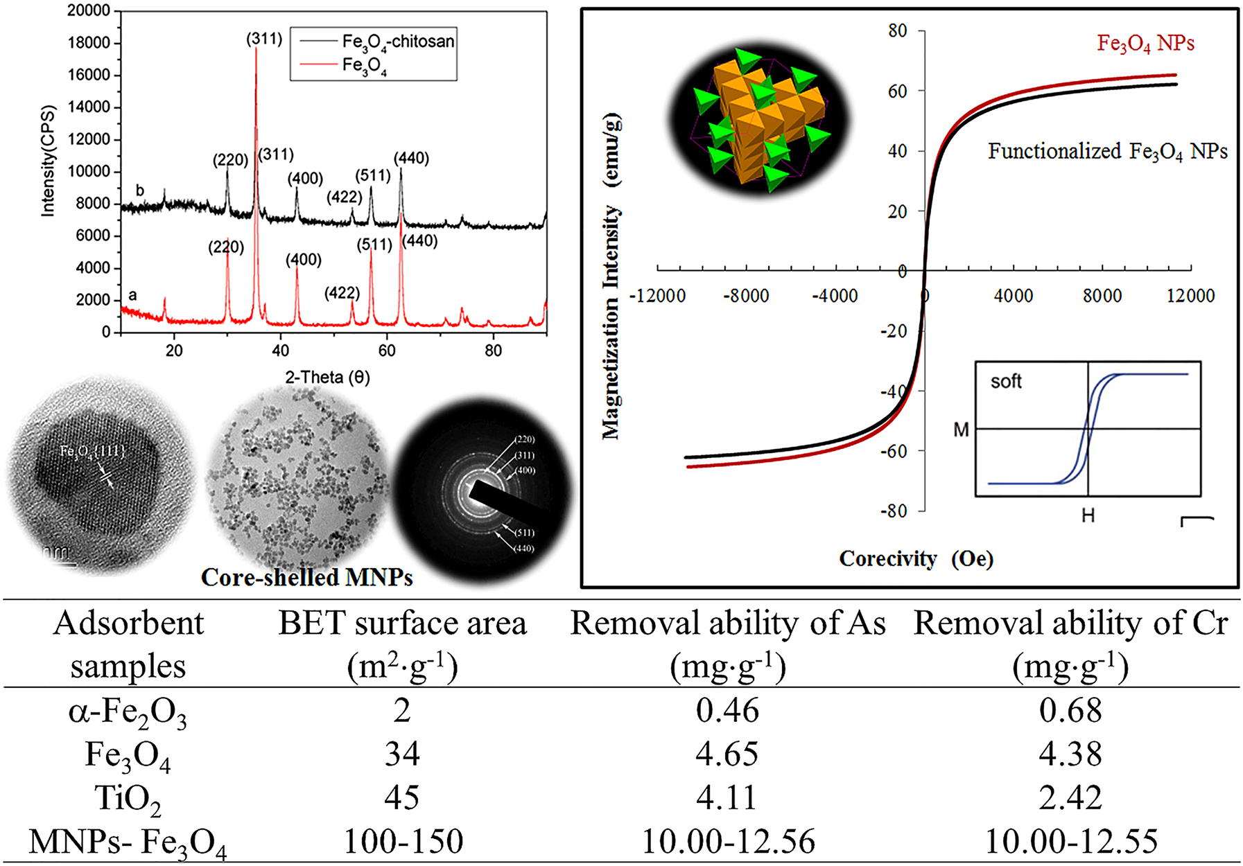
The magnetic nanomaterials with improved removal ability of heavy metal oxyanions through reduction-oxidation reaction using bio-formulated Fe3O4 NPs (TiO2 and α-Fe2O3: commercial samples; Fe3O4: reported data).
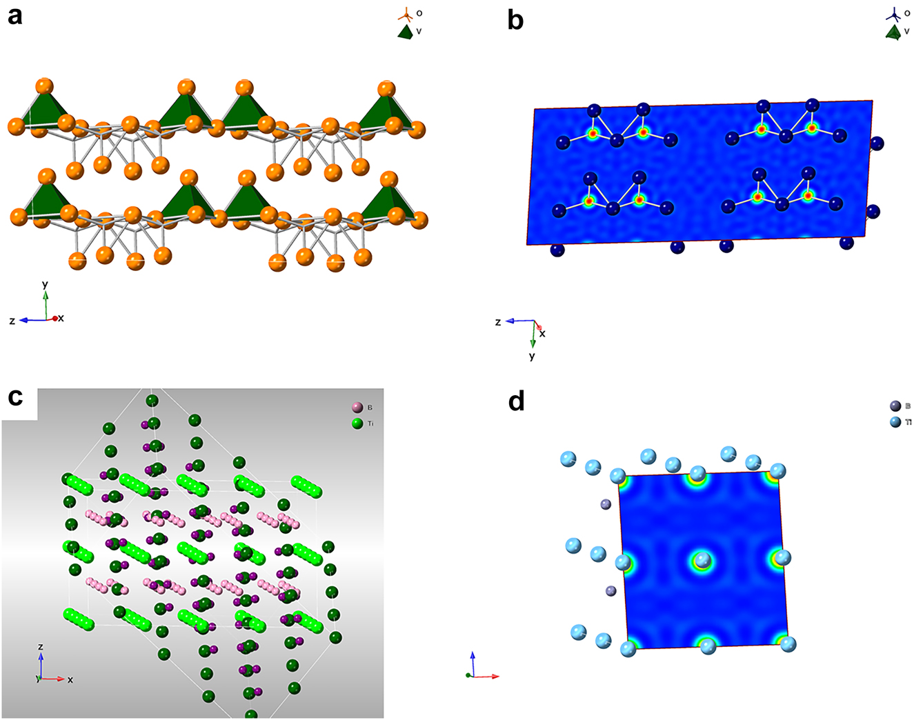
The electron density of materials used in energy conversion and storage, (a): The crystalline structure of V2O5; (b): The electron density of V2O5; (c): The crystalline structure of boride (TiB2), and (d): The electron density of TiB2.
Physical properties
It is commonly agreed that the nanomaterials showed an ultra-high surface effect, ultrahigh volume effect, and quantum size effect. Many atoms on the surface are the major reason for the ultra-high surface effect. Based on the calculation, the surface atoms account for about 20 % of the total atoms within “perfect” nanomaterials, with the size decreased to 10 nm. With future size decreased to 1 nm, the surface atoms account for up to 99 % of the total number [20]. This observation suggested the existence of the dangling atoms, which show high potency to form chemical bonds with other atoms to stabilize the system energy. Our photocatalysts (rGO-TiO2) used in water remediation displayed ultrahigh chemical reactivities due to the surface effect. We also found that the particle size deduction will decrease the bandgap due to the quasi-discrete energy of electron configurations. Our previous study indicated that the bandgap between the highest occupied molecular orbital (HOMO) and lowest unoccupied molecular orbital (LUMO) was tunable by varying the synthesis variables (Fig. 3). Nanoclusters of decreased dimensions impact the electronic structure through energy changes on the valence band between the HUMO and the conduction band of the LUMO [21]. Optical properties like absorption and emission transitions and line strength are connected to changes between these bands. Other changes in the size of nanoparticles will alter the physical and electronic properties, such as color and conductivity in semiconductors and metals [22].
Magnetic properties
One family of metal oxide, iron metal oxide (Fe3O4), showed ferromagnetic property due to unpaired electrons in the d-orbitals and their sensitivity to magnetic fields. Those materials are intrinsically magnetically ordered and develop spontaneous magnetization even though an external magnetic field is not applied. The ordering mechanism is the quantum mechanical exchange interaction. One of the main concerns in producing magnetic particles is to control their sizes and size distribution. Magnetic particles with ultrafine tend to agglomerate, which will lower their vitality because of their high surface tension. However, this vitality is directly linked with these nanoparticles’ high accessible surface region and volume degree. On the other side, these metallic or magnetic nanoparticles are synthetically dynamic; can be oxidized in the air resulting in loss of the magnetic property and dispersibility [23]. To widen the applications of these magnetic nanoparticles, the author treated these particles with natural product extracts, which behave like surfactants, polymers, and other inorganic layers (such as silica or carbon). This treatment also prevents the nanoparticles from debasement and protects them from losing attractive properties (Fig. 4). It is also an important outer layer, or the shell of these nanoparticles must be chosen based on the functions, and the applications as the shell can be made from different ligands [24]. The functionalized nanoparticles can be used in diversified fields, as mentioned above. This functionalization enhances the high scattering, high reactivity, and simple detachments. Now, these magnetic nanomaterials should be blended using different techniques which do not involve oxidation and corrosive disintegration as the security of the particles is essential [25]. The bioencapsulated Fe3O4 magnetic nanoparticles functionalized by natural plants were found to show high removal efficiency of As (V) and Cr(IV). These bioencapsulated MNPs (0.5–5.0 mg) will be introduced into an aliquot of 20 mL Na2HAsO4 and Na2CrO4 solutions with different concentrations. The mixtures will be under agitation using an orbital shaker for 24 h to reach an equilibrium. The adsorption will be performed under different pH values (5–9). The As(V) and Cr(VI) concentrations in the remaining solutions will be determined by an inductively coupled plasma-optical emission spectroscopy (Optima 5300DV). The adsorption isotherm will be obtained by varying the initial As(V) and Cr(VI) concentrations. The relationship between the MNPs’ removal ability and the solution concentration of the contaminants Ar(V) and Cr(VI) was improved from 0.68 to 12.6 mg g−1 in comparison with the reported data (Table 1) [26].
Summary of adsorbent sample, surface area and heavy metal removal ability.
| Adsorbent samples | BET surface area (m2 g−1) | Removal ability of As (mg g−1) | Removal ability of Cr (mg g−1) |
|---|---|---|---|
| α-Fe2O3 | 2 | 0.46 | 0.68 |
| Fe3O4 | 34 | 4.65 | 4.38 |
| TiO2 | 45 | 4.11 | 2.42 |
| MNPs-Fe3O4 | 100–150 | 10.00–12.56 | 10.00–12.55 |
Electronic properties
The Bohr model of the atom (H as an example) depicts the atom as a small, positively charged nucleus surrounded by electrons that travel in circular orbits around the nucleus. Within the atoms, nuclei provide electrostatic attraction to the electrons, while electrons repel from each other. According to the principal quantum number, the shells in a Bohr-type atom occupy three-dimensional space, corresponding spectroscopic labels K, L, M, N [27]. which was used to describe chemical stability across the periodic table in terms of half-full or complete shells. Normally, this phenomenon will be observed if the particle sizes are comparable to de Broglie’s wavelength of electrons [28]. Below a critical size length, conductors become insulators due to the separation of conduction and valence bands. When the system length scale is reduced, changes in electronic properties are related mainly to the increasing influence of the wave-like property and the scarcity of scattering centers based on quantum mechanical effects [29]. When the particle size is comparable with the de Broglie wavelength (λ = h/mν, h represents Planks constant; m the mass of the particle and ν the velocity) of the electrons, the apparent differences between the energy states can be observed, where the electrons are confined in all three dimensions [30]. The electrons can move freely between adjacent nanostructures, defined as the quantum tunneling effect, since the barriers are lower than expected under classical mechanics of larger bodies, enabling movement. The purpose of this electron configuration analysis is to understand the likelihood of co-alloying metals to lower energy levels and enable catalysis to occur at lower input energies. A common example is the incorporation of Gd, where the f-orbitals of the metal are available for bonding from oxygen with cobalt oxide, for example, in a semiconductor-based catalyst. In our example, boron is used as an electron-deficient ‘sink,’ which also has excellent stability under alkaline conditions, with vanadium oxide as the capacitor storage material. The de Broglie effect enables efficient charge separation and twinned ion channel paths for both charge species and oxygen diffusion. Under external voltage, the discrete energy levels are aligned due to the propensity of dative bond formation and charge transport to enhance charge storage. This perspective demonstrated the electron density (Fig. 5) of V2O5 used for supercapacitor and TiB2 for microwave absorption.
Applications of nanomaterials
Solid oxide fuel cells
Solid oxide fuel cells (SOFCs) use a thin layer of ceramic-based rapid ion conductors as a solid electrolyte. The SOFCs have been developed for stationary and portable applications, such as in various auxiliary power devices. SOFCs normally operate a high-temperature range of 700–1000 °C with yttrium-doped zirconia (YSZ) electrolytes and as low as 500 °C with Samaria-doped ceria (SDC) electrolytes [31]. These SOFCs can internally reform natural gas and biogas and can be combined with a gas turbine to produce electrical efficiencies as high as 75 %.
Electrode catalyst
This section will discuss the ABO3 and ABO3-A2BO4 series of electrode catalysts to demonstrate their synthesis, structural characterization, and electrochemical performances. A facile colloidal synthesis was used to prepare La1-xSrxCo1-yFeyO3-δ precursor with tuneable the polymeric frameworks (Fig. 6a-1), which will be subject to calcination for crystallization. When the chemical process incorporates these principles to manipulate the structure and property of the nanomaterials, the “green” outcomes are achieved in reducing the production of hazardous wastes and increasing great energy efficiency [32]. This approach has additional benefits of generating minimal waste, offering low manufacturing costs, and ease of operation. This strategy has the advantage of controlling materials preparation from the molecular/atomic level and guiding the development of nanoscale materials to provide the maximum benefit of these products for society and the environment [33]. The second method, sputter deposition (Fig. 6a–2), was used to prepare ABO3-A2BO4 (La0.6Sr0.4CoO3-(SrLa)CoO4) and followed by the calcination at various temperatures. The sputtering variables were optimized and controlled: the power to initiate plasma at 90 W, power to deposit film at 20 W, Ar flow at 8 mL/min, and the partial pressure of the gaseous atmosphere at 1.0 atm. The deposition time of the ABO3-A2BO4 thin films could vary according to the thickness, and it was controlled at 16 h in the current experimental set-up. The sputtered samples were then calcinated at various temperatures, ranging from 400 to 900 °C with an increment of 100 °C under the heating rate of 10 °C/min. Heat-treatment can be conducted under the oxygen (O2) or argon (Ar) atmosphere for both family’s perovskite materials. The calcination duration was varied significantly to understand the influence of the diffusion co-efficiency of the cations [34].
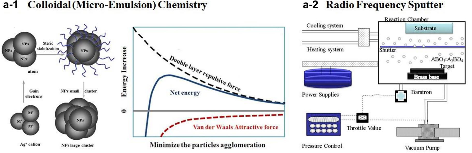
The preparation of cathode catalysts used in solid-state chemistry using colloidal wet-chemistry and sputtering deposition, followed by calcination for crystallization.
The purpose of the fabrication techniques is to give more control over the selective deposition of perovskite ceramic material, including the predefined thickness of the electrode, to promote facile ion transport at higher temperatures. The literature summarizes multiple synthetic approaches, which all have a similar aim. We applied facile non-stoichiometric syntheses to introduce A-site vacancies, which caused lattice strain and enhanced the degree of covalency between the metal and oxygen. This covalency is attributed to electron filling in the metal cation and overlapping between 3d (transition) or 4f (inner transition) to 2p orbital overlap to increase the catalytic ability of catalyst on the oxygen reduction reaction. Our approach was to couple facile colloidal synthesis with sputtering to introduce the catalyst-electrode assembly for chemical conversion to electricity at the SOFC device level of integration.
Structural evaluation
The spectroscopy, electron microscopy, and X-ray diffraction were systematically used to evaluate the crystalline phase, morphology, and elemental composition of different cathode catalysts and composites. The Ultima IV X-ray powder diffractometer, with high-temperature features, was used to determine the crystalline phase of the SOFC cathodic catalyst. The parallel beam geometry was applied for all tests under various temperatures to eliminate the systematic errors caused by the sample thermal expansion, surface displacement, and deformation. The temperature range was controlled from ambient conditions to 900 °C with the increment of 100 °C under a heating rate of 10 °C/min (Fig. 6b-1). Quantitatively, the average crystalline size was calculated according to the Scherer equation. The William-Hall equation was also used to determine the micro-stress of the cathode catalysts with the temperature changes. Both scanning and transmission electron microscopic analyses were employed to determine material characteristics at the micro- to the nanoscale. This multiscale and multi-modal analysis of morphology and defects allows for reliable and informed decisions for process control of materials preparation and design improvement.

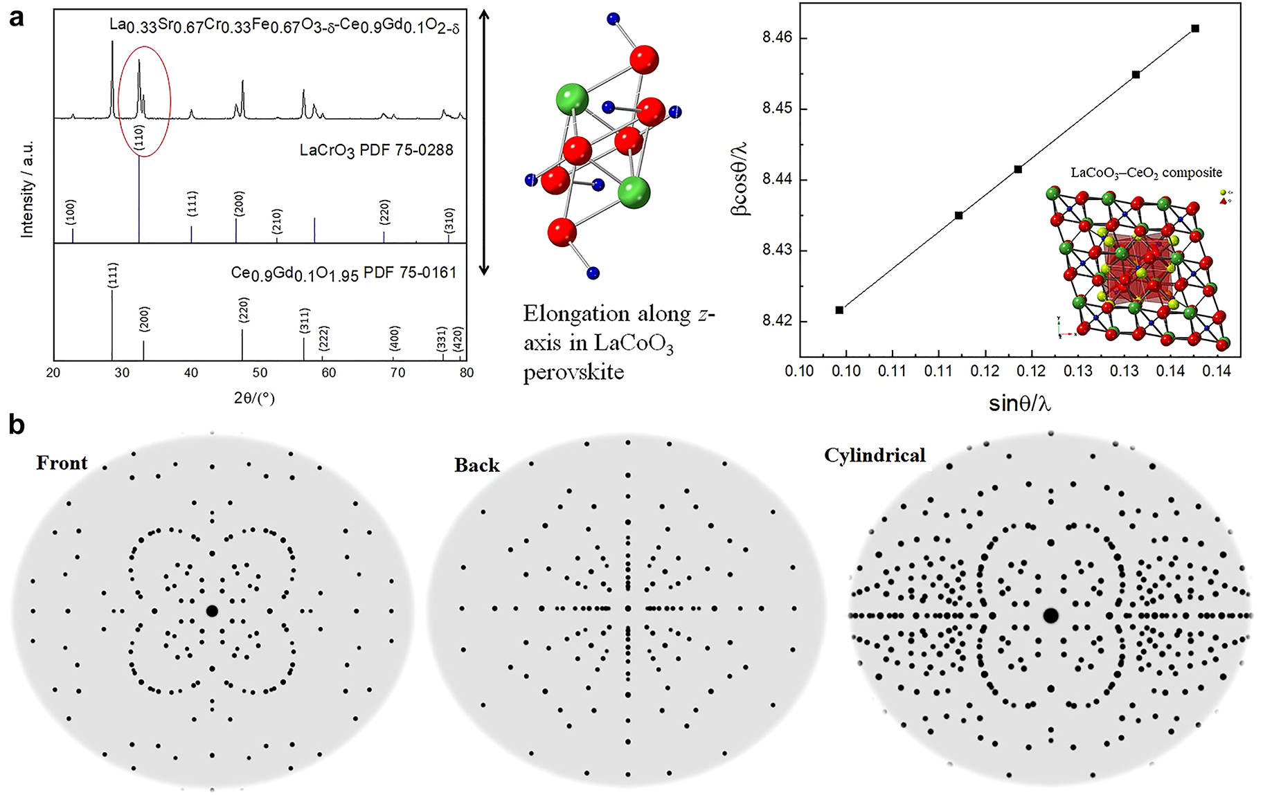
The X-ray powder diffraction analysis of Pt-modified perovskite cathode catalysts (LaSrCoFeO3) used in solid oxide fuel cells under different temperature gradients.
The La0.8Sr0.2Co0.8Fe0.2O3 (LSCF) and cathode on Sm-doped Ceria (Sm0.2Ce0.8O2) were obtained after heating at 900 °C for 4 h at air atmosphere. The typical XRD pattern (Fig. 6b–2) aligns well with the standard perovskite LSCF (unit cell of tetragonal, JCPSD 89-1264). Our results are consistent with the report by Riza and his co-worker [35], whose study showed a degree of distortion from tetragonal to orthorhombic. The fine scanning at 2θ of 31.5° indicated a peak splitting due to the elongation along the z-axis. This elongation was the major reason for non-uniform micro stress, in this case, lattice distortion. Dr. Wang and his group [36] reported the phase transition of LSCF from rhombohedral to cubic, suggesting the deformation of the crystalline phase may depend on the dopant amount of Fe ion and its charge density. Our study also suggested that this lattice distortion is associated with the isostructural atomic re-ordering. The Waller group [37] observed that a quantity of strontium is not incorporated into the perovskite lattice. The symmetry perovskite has an A-site deficiency. The deficiency at the A-site may result in a certain amount of oxygen vacancies, consequently, improve the current exchange density. Two different phases of Fe3O4 and a-Sr from LSCF perovskite seem to be formed at >600 °C, which also more or less hindered the LSCF growth. The metal oxide formation acts as a double-edged sword, preventing particle growth while decreasing the electrical conductivity. The crystalline size of the sol-gel derived LSCF, and its composite was distributed from 20–40 nm. Due to this high specific surface area, the current density was improved by one order in magnitude. In short, our study on phase transition, crystallite growth, and thermal expansion indicated that the parallel beam geometry eliminates the systematic errors caused by the sample thermal expansion and surface displacement and deformation.
The XRD pattern at the different temperatures indicated that crystalline phases composite ABO3-AA′BO4 (La0.6Sr0.4CoO3-(SrLa)CoO4) corresponds to the International Centre for Diffraction Data (ICDD) standards. Two distinctive phases were obtained, rhombohedral La0.6Sr0.4CoO3 (00-036-1393, a = 5.427 Å, c = 13.218 Å, a = 90°, Space group:
Electrochemical performances
The electrochemistry performance of the LSCF catalysts was determined using cyclic voltammetry and AC impedance (Fig. 6c). The IR compensated I/E data (Fig. 6c-1) were obtained using the positive feedback method collaborating with Dr. V. Birss. The exchange currents, i 0 , obtained from these low field measurements has increased from ca. 0.25–250 mA cm−2 by increasing the temperature from 400 to 700 °C, which corresponded with the data obtained from AC impedance measurements (Fig. 6c-2) [40]. The charge transfer resistance (R ct ) value of 0.31 Ω cm2 of LSCF cathode at 700 °C is one order less than that of 2.03 Ω cm2 reported by Yuan Ji and his colleagues and similar to the area-specific resistance of 0.287 Ω cm2 by Steele [41]. The results showed that sol-gel technology has the instinct advantage of forming cathodic materials with large specific surface area and good homogeneity and high porosity. Therefore, after heat treatment, nanoscale cathodic material with a stable structure can be obtained, which will result in stable electrochemical property and reproducibility. It was also found that with the increasing cathodic applied polarization potential, there was no significant change in R ct of LSCF, which implied that homogeneity material had been obtained. For efficient fuel-cell operation, a value of R c < 1 Ω cm−2 is desired [42]. The LSCF cathode formed from the sol-gel method displays lower resistance that ca. 0.30 Ω cm2 at 700 °C. However, at a lower temperature range of 600–400 °C, the cathode exhibited higher resistance with a value of ca. 2, 16, and 200 Ω cm2 respectively. Dr. Kim and his co-workers reported that cathodic composite of LSM and LSCF formed by traditional solid-state powder reaction exhibited good performance of 375 mA cm−2 at 750 °C [42]. Our study of pure LSCF formed by sol-gel technology displayed high exchange current density with the value of ca. 250 mA cm−2 at a temperature of 700 °C. The noble metal Pt-modified LSCF showed significant improvement in both current density and charge transfer resistance. However, the in-situ exsolution was found, which hindered the long-term stability of the SOFC devices [43].
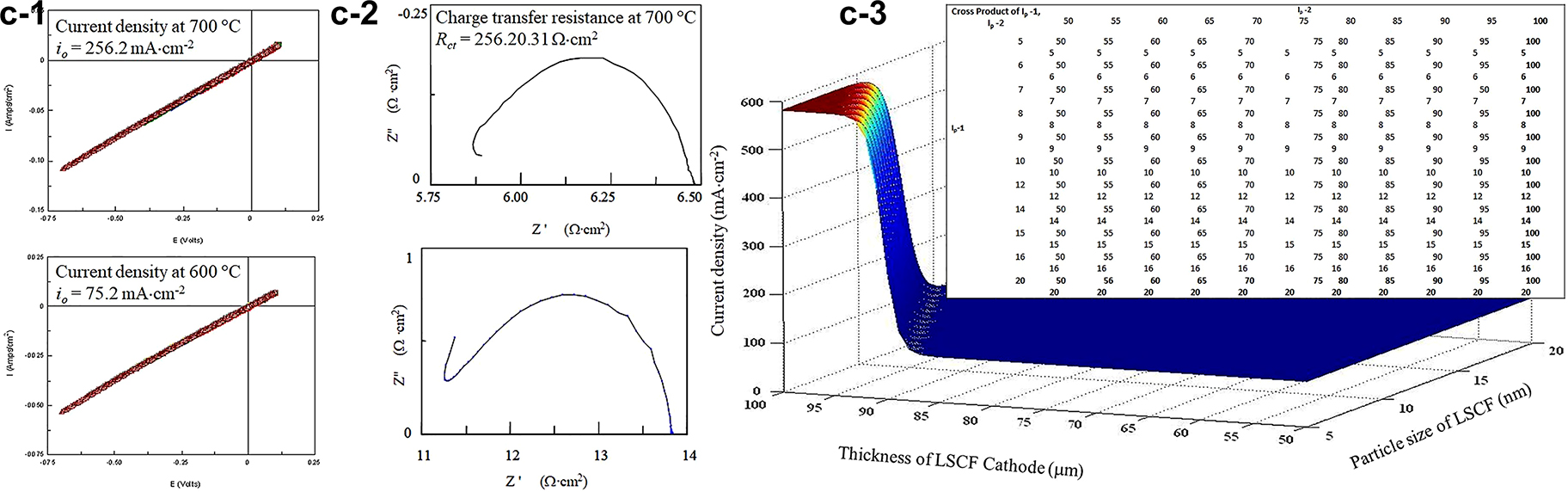
LSCF perovskite cathode catalysts, (1): CV studies of ORR at SG LSCF cathode treated at high temperatures, ranging from 400 to 700 °C, 20 mV/s, Air, IR compensated; (2): AC impedance analysis of the catalyst at a different frequency, 0.05–106 Hz; and (3): The ANN simulated current density as a function of cathode thickness and particle size.
To mitigate the drawbacks of the traditional error-and-trial method, we implemented the artificial neural network (ANN, Fig. 6c-3) in the SOFC cathode screening. Based on the “fit” trials, we propose to combine the ANN modeling and SOFC cathode design to increase the accuracy of our experimental results. ANNs are a class of computer algorithms that attempts to mimic the inference logic of the human brain. ANNs have been used widely in image processing and data classification applications. We found that the most reliable ANN model assists us in predicting the performance of the fuel cell materials [44]. Function_Approx.m and simulation were implemented on the Matlab™ workspace in our previous study. The inputs of the M_1 model included concentration of starting materials (Fe(NO3)3), viscosity of LSCF colloid, catalyst heating temperature, and uncontrollable fabrication variables, and the outputs were catalyst characteristics including particle size (D), the thickness of LSCF (d), and zeta-potential (ζ). M_2 mapped from catalyst microstructure and single-cell measurement variables to current density to predict SOFCs single cell performance. M_2 used catalyst microstructural characteristics (D, d, ζ), oxygen flow rate, operating temperature, and uncontrollable cell test variables as inputs and current density (i o ) as outputs. The trained ANN model was applied to simulate the SOFC cathode performance using microstructural characteristics, O2 flow rate, and performance measurement temperature as inputs and current density (i o ) as outputs. ANN model mapping inputs denoted as I p , to output denoted as O p of performance evaluation was constructed based on the data of particle size (I p -1), thickness of cathode (I p -2), zeta-potential (I p -3), oxygen flow rate (I p -4), measurement temperature (I p -5) and current density as the output. These values are close to the state-of-the-arts values for the microdevice at approximately 250 mA cm−2 [45].
Solid oxide electrolysis cells
Ball-milling preparation of perovskite catalyst
Different formations of non-stoichiometric cathodic powders (La0.33Sr0.67Cr1-xFexO3-δ) were prepared by an optimized ball milling approach ( OBMA ). The ratio of reactants vs. milling balls, ball diameters, rotation rates, and pre-post low-temperature heat-treatment were optimized in this study to obtain homogeneous particles, although thermodynamically metastable [46]. The advantage of this technique is the ability to tailor size both in wet and dry conditions to obtain particles with rough surfaces to increase oxygen adsorption. OBMA produced materials have better catalysis due to improved oxygen reduction through O2− anion diffusion and surface exchange. These processes led to better-distributed atoms catalysis than traditional wet sol-gel synthesis. These nanostructured green powders were then used to construct half-cell and solid oxide electrolysis cells (SOECs). The half-cells were subject to test for their electrochemical reactivity to facilitate NH3 production. Our study chose two different-sized marble balls to provide high impact forces, frequencies, and acceleration. Those balls were found to be projected into the milling chamber and then “cascading” down at different rates, resulting in efficient crushing of all fed reactants, LSCrF, and GDC powders. The quantity of these reactants was controlled at a maximum, 100 % to improve the rate of OBMA milling. The speed of rotation and the coefficient of friction of the fed reactants were also optimized based on our previous experiments to ensure the high efficiency of the milling operation.
Structural characterization
The X-ray powder diffraction results showed that the formation of A-B sites dual-doped LaxSr1-xCryFe1-yO3-δ (LSCrF) powders and corresponding LSCrF-GDC composites (LaCrO3, (PDF): 75–0288, a = 3.88–3.91 Å, c = 7.76 Å, α = 90°) polycrystalline phases with an acceptable frequency of merit. The major diffraction peaks appearing at about 32.50°corresponded to the (101) plane, which showed peak splitting (Fig. 7a), indicating the lattice micro-distortion occurred. It was found that the Fe3+ amount increase resulted in more evidential peak splitting and the diffraction moved toward a smaller angle, indicating an elongation of crystal lattice along the c-axis. This phenomenon resulted from the large ionic size of Fe3+ than Cr3+. The high-resolution transmission electron microscopic (TEM) images (Fig. 7b) were collected under steady incident multi-beam, indicating a well-crystallized particle and pore size uniformity of the LSCrF nanocatalyst with four different formulations. It was found that the molar ratio of Fe3+ (0.67 Å) and 11 mass % of PMMA was the optimal amount of porogen, from which all catalysts were prepared under this synthesis condition. The LSCrF has an average of 10.5 nm (±0.15 nm) with high integrity and well-defined domains. In the composite samples, both LSCrF and GDC were detected with high crystallinity. Upon turning the pore structure using PMMA-5, the LSCrF was well-distinctive, while some of their edges and corners were subject to polarization and distortion, which can act as the reactive sites to enhance NH3 production. It is anticipated that, with the Fe3+ amount increase, the secondary phase of SrCrO4 may occur, as shown in the XRD analysis. However, the impact of this observation will be evaluated to optimize the synthesis variables further and maximize the NH3 production efficiency in future studies. In general, the electrode surface roughness was proposed to provide a large triple phase boundary, favorable for the gaseous reactants’ adsorption and further production formation.
The LSCrF-GDC composites as the SOEC catalysts, (a): The XRD pattern indicating the z-elongation occurrence resulted in lattice distortion; and (b): The simulated LaCoO3 crystal showing the well-crystallized catalysts formed using ball-milling synthesis.
SOEC used for green synthesis of ammonia
To overcome the challenges of using traditional methods to produce NH3, our groups invented a SOEC method to produce NH3 [47]. It was found that the current density significantly dropped from 95 to 80 mA cm−2 and then stayed at constant values with the increase in reaction time duration for ammonia production using this electrochemical green method. This observation is only seen under 600 °C and 1.6 V, in which the mechanism remains mysterious for our group at this point. High applied voltage essentially generated a high current density, indicating a high NH3 production yield. The study on the stability of the reaction rate within 3 h was evaluated, suggesting the current density changed by ±0.62 % for majority studies (Fig. 7c). However, spikes were noticed due to the fluctuation of the electrochemical reactivities. As a general tendency, the electrodes are stable over time at OCV, as shown be by the deviations of current density varying by ±0.62 %, except the measurement at 600 °C at 1.6 V. LSCrF electrode appears to be stable under the test conditions without any signs of ongoing phase segregation or decomposition as evaluated by XRD. The secondary Sr-chromite phases that initially were present seem to re-dissolve into the perovskite within 10 h at 1000 °C. The substitution of the La site and Cr site with the other elements can decrease the sintering temperature and increase the electronic conductivity. Because interconnects must separate fuel and oxidant gases, the LaCrO3-based perovskite should be a dense body. However, alkaline earth-doped or non-doped LaCrO3 with stoichiometric compositions (La/Cr = 1) are difficult to sinter in an air atmosphere because of the vaporization of chromium vapor-phase transports, which causes grain growth without densification. Doping of alkaline earth with liquid-phase formation can reduce the sintering temperature and improve densification. Doping Sr into LaCrO3 (La0.84Sr0.16CrO3) markedly increases the sintered density when 3–5 mol% excess SrCO3 is added as a sintering aid before firing in a reducing atmosphere around 2200 K. Liquid-phase formation was also observed in La0.76Sr0.24CrO3 and Y0.6Ca0.4CrO3. Because of limited alkaline earth solubility, melting chromates, SrCrO4 and CaCrO4 precipitated from the perovskite structure at intermediate temperatures. These liquid-phase chromates enhance the densification of doped LaCrO3 at high temperatures. The major advantage of ammonia synthesis by SOEC is conducting the reaction at ambient pressure compared to the Haber-Bosch process. The high temperature and pressure are required in the Haber process due to the large endothermic energy attributed to the high energy cost of nitrogen bond dissociation enthalpy. In contrast, the redox couple supplied the reducing ‘equivalence’ in the electrolyzer process and conducted it at low pressure (Fig. 7d). Like the Haber-Bosch process, high temperatures are required to make the reaction kinetics acceptable on an industrial scale. The electrochemical production of ammonia at low pressure will reduce engineering costs and make ammonia synthesis more portable in that large engineering stations are not required. While electrochemical synthesis of ammonia is a step forward, it is not comparable to the biosynthesis of ammonia by nitrogenase-containing microorganisms. The catalytic center usually consists of a dinitrogenase reductase (Fe-containing) and dinitrogenase (Fe/Mo containing) domain. Electrons are transferred from reduced ferredoxin (Fe) to molybdoferredoxin (Fe/Mo). Each mole of fixed nitrogen requires 16 mol of adenosine triphosphate (ATP) to be hydrolyzed to adenosine diphosphate (ADP) and inorganic phosphate (Pi). Under ambient conditions, ammonia is biosynthesized; however, the reaction rate is slower than that observed with SOEC. The biosynthesized ammonia is often converted into ammonium and incorporated into proteins, which hinders the application of microbial-assisted biosynthesis of ammonia. The next section briefly outlines how microorganisms convert simple sugars to carbon dioxide or lactates and electrical power through exoelectrogenesis [48].
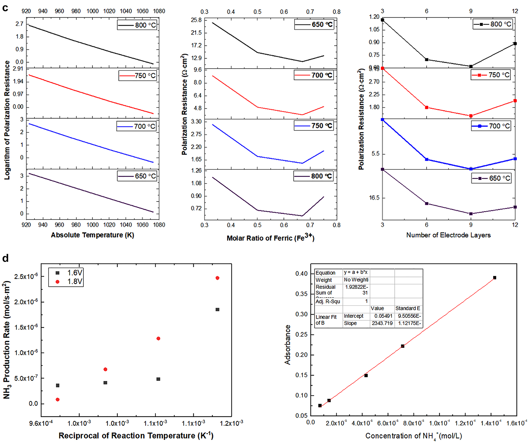
Electrochemical performance of LSCrF-GDC with different A and B-site doping used as the electrocatalyst; (d): NH3 production using the solid oxide electrolysis cells, showing high production rate in comparison with traditional methods.
The design criteria between a SOFC and SOEC are similar, but the operational mechanisms are different. The purpose of the anode electrode (e.g., Ni-YSZ) in a SOFC device is to provide mechanical strength and to limit polarization losses. The design of the electrolyte aims to enhance ionic conductivity and material compatibility. The cathode electrode extends the triple-phase boundary and offers low ohmic loss. The purpose of the SOFC is to generate electricity using fuel and oxidants. SOFC can operate at 0.7–1.00 cell voltage (V) using hydrogen as the preferred fuel, which involves a four-electron oxidation reaction. The electrons are transported from the anode to the cathode through an external circuit, while the oxygen anion diffuses through the solid electrolyte in the opposite direction. In SOEC mode, external power input is applied to facilitate the redox reaction. In electrolyzer mode, as reported by Vikrar, the oxygen partial pressure inside the device increased, resulting in delamination of the electrode surface, which needs to be considered at the device level of integration [49]. In our example, ammonia is formed in the cathode chamber using nitrogen and water steam as reactants. The ammonia formation occurs at 550 °C with an applied voltage (1.6 V) without pressure build-up.
Microbial fuel cells
The microbial fuel cells (MFCs) have been rapidly developed, focusing on concepts, termini, and materials design based on their end applications and commercialization [50]. The MFC performances highly depend on the electrode properties, potential of redox couples, design of polymeric membranes, nature of the substrates, and operational conditions, as discussed in the proceeding sections [51]. Usually, power density, current density, and cell voltage are the main indicators to demonstrate the MFC’s performance and another electrochemical perspective (charge transfer resistance and durability) under different measurement conditions [52, 53].
Single-cell assembly
The MFC system’s power output and long-term stabilities will be affected by a strain of microorganism, type of substrate, oxygen tension, microbial growth rate, substrate affinity, kinetic and biomass transfer, and thermodynamics of the anodic reaction. A series of interactive biofilms were prepared by enabling an attachment between select extroelectrogenic microbe (bacteria and yeast) to the nanostructured anode surface via an active “sucking” attractive interaction. Upon nano-modification, these biofilm anodes are anticipated to respond to the external environmental changes and self-regulate their structures. To better understand how microorganisms such as sulfur-reducing function on the anode surface, an anodic compartment was assembled using the select yeast (Saccharomyces cerevisiae). The media, composed of glucose enriched phosphate-buffered saline (PBS), was used, and yeast was harvested in the late exponential phase by centrifugation under anaerobic conditions. The cell pellets were suspended in a freshwater medium without an electron donor or acceptor and inoculated into the anode chambers. In addition, a suspension composed of graphene and other inorganic catalysts was introduced into the above anodic media. The resultant biofilm anodes (Fig. 8) were found to show high conductivity due to the extension of electron transfer by conductive microorganisms.
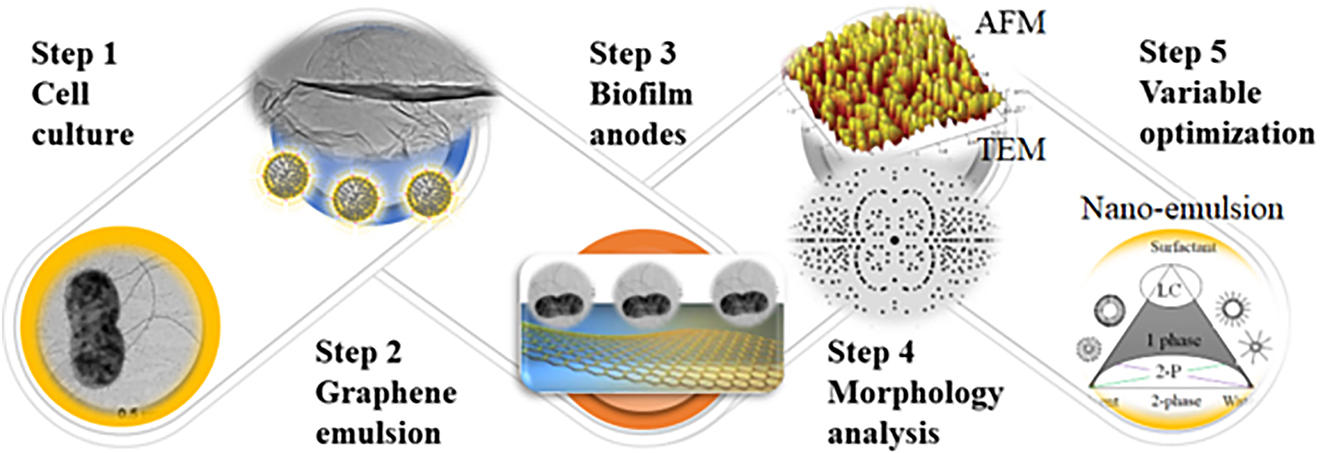
The performance of MFC devices using electrocatalysts to form biofilm using graphene as support.
Device performance
Cyclic voltammetry (CV) and electrochemical impedance spectroscopy (EIS) will be used to evaluate the MFC performance. A two-chamber MFC power system (Fig. 8b) was constructed using the above anode and a polymeric PTS membrane (developed in Liu’s lab). The configuration, substrates, and measurement conditions have been controlled and optimized to secure high maximum power density. Although the conductivity of prepared anodes is anticipated to improve power output generated by the MFCs, the mixed cell culture shows its potential application for the advancement of MFCs due to its synergistic effects of different components. The nano-emulsion allows for formations of interactive nanomaterials by a simplified feasible wet-chemistry, securing a homogeneous tunability of structure and properties from the molecular or atomic level. The current density was highly dependent on the microbial surface coverage, suggesting the use of multilayer biofilm increasing anode current. Production efficiency per cell can be correlated with biofilm thickness even when the outer layer is significantly distant from the anode surface. Viability staining indicates cell viability to biofilm thickness to current as cells are expected to grow at a distance from the electrode surface divide during biofilm development, suggesting if the cells are metabolically active and involved in electron transfer from microbes to the anodic electrode [54].
Mechanism study
The proposed mechanism of oxygen reduction reaction (ORR) involves a multielectron transfer process with five elementary steps, namely, O2 adsorption, reduction of O2ads through two processes; desorption of product of H2O2; reduction of reduction H2O2ads , and desorption of adsorbed H2O [55]. Previous data reported by Logan et al. have demonstrated that they can produce micrometer-long proteinaceous. These appendages can extend from their outer surface into the extracellular matrix, involved in extracellular electron transport processes. The biofilm anodes displayed two properties: a conductive solid matrix characterized by the biofilm conductivity and accepting electrons from microbes and conducting these electrons to the anode [56]. The biofilm conductivity strongly influences the electron-donor (ED), current fluxes, and biomass distribution. The conductivity was correlated to an increased ED and current fluxes under different conditions, such as carbon sources, biofilm thickness, and strain of microbes. Our study inferred two possible modes of the current generation: direct and indirect electron transfer. The first mode by direct electron transfer mechanism involves electron transfer via conductive pili, where the microbial nanowires act as conductive channels. The second mode is indirect electron transfer via redox-active protein, where the microbe extrudes redox-active molecules into the extra membrane space. By careful adjustment of the redox potential of the mediators, a charge transfer shuttle enables indirect electron transport. The modified biofilm anodes are anticipated to directly contact the microorganisms, further promoting electron transfer due to graphene’s high conductivity. A microorganism capable of forming nanowires can extend its proteinaceous filaments into the extracellular matrix to facilitate electron transport. The redox-active microbial membrane proteins also allow for short-range electron transfer without physical contact between microbe and electrode. These electrons can be transferred to the electrode surface from the conductive proteins such as C-type cytochromes [57].
Super-capacitor
Ternary metal oxide selection
Among the consortia of energy power systems, the supercapacitors are one class of electrochemical storages that have been systematically studied for several decades due to their rapid charge-discharge properties, improved power density, and enhanced efficiency cycle stability. We demonstrated self-regulatable heterojunction configurations composed of manganese (IV) oxide nanoparticles (MnO2) grafted vanadium (V) oxide ribbon arrays (V2O5) to enhance their super capacitive performance. During the two-step hydrothermal reaction, an endothermic metathesis of NH4VO3 resulted in the formation of V2O5, while reduction of KMnO4 leads to the formation of nanoscales MnO2 under 180 °C (Fig. 9a–d). The surface-bound Mn4+ cation was nucleated under high pressure to form [MnO6] octahedra building units, then formed MnO2 phased NPs during the hydrothermal treatment (Fig. 9c and 9f) under various temperatures and pressures. These surface Mn atoms enable attraction with the negative oxygen end from V2O5 single-crystal units through ion-diploe intermolecular forces. This attraction allows for the formation of twinned channels and strong adhesion through which charge transport can occur between two crystalline phases at their interfaces. These attractive forces ensured ion intercalation into a redox-active material without causing crystallographic phase collapse. The XRD data showed orthorhombic V2O5 well-indexed with the standard (JCPDS: 41–1426, a = 11.516 Å, b = 3.5656 Å, c = 4.3727 Å, α = 90°, space group: Pmmn (59)) and tetragonal α-MnO2 (JCPDS: 44–0141, a = 9.7847 Å, c = 2.8630 Å, α = 90°, space group: I4/m (87)). The XRD spectra suggest that both α-MnO2 and V2O5 crystalline phases were maintained well after grafting. These grafted structures were found to be assisting Li-ion insertion, allowing for rapid ionic conduction and an improved supercapacitor performance. The well-organized interleaved structure significantly improved their capacitance (10–20 times) and energy density (>10 times) compared with the published data [58, 59]. Multiple factors have been considered for selecting two metal oxides, MnO2 and V2O5, as the supercapacitor electrodes, particularly their potential windows in an aqueous solution.
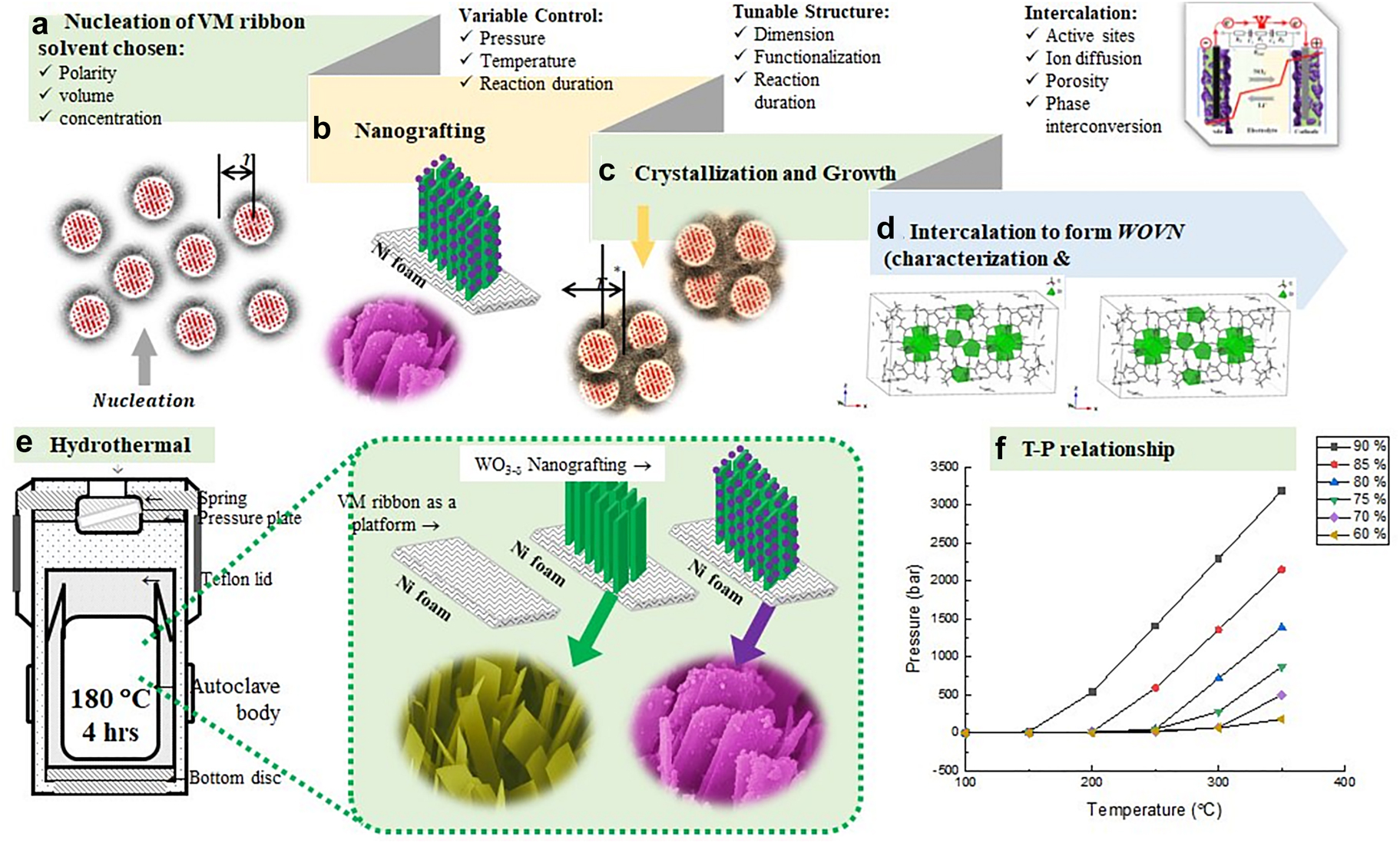
Hydrothermal synthesis to create bi-metallic oxide electrode heterojunction structure; (a): Nucleation of metal oxides under optimized synthesis variables; (b): Nanografting to form desired crystalline phases and morphology; (c): Crystallization and particle growth due to the thermal motion; (d): Intercalation to form heterojunction structure, offering shortened spontaneous pathways to facilitate ion diffusion and electron conduction; (e): The schematic of hydrothermal synthesis to produce grafted heterojunction structures; and (f): Relationship between reaction temperature and pressure.
Electrochemical performance
The heterojunction materials were used as the anode and cathode electrodes to assemble symmetrical supercapacitors (SC: 1.0 × 1.0 cm2 in length and width with a thickness of 0.02 cm) in two configurations, the first using V2O5 defined as VSC and the second using MnO2 grafted V2O5 as MVSC. The CV profiles were collected under different applied voltage and scan rates, respectively. The CV spectra indicated a distinct polarization for both devices (Fig. 10) were observed at the voltage window at 2.0 V. The specific capacitances of MVSC were 370, 258, 216, 189, and 162 F g−1 at different scan rates (5, 10, 20, 50, 100 mV s−1), showing an average 15.4 % increase, compared with the VSC systems (Fig. 10a). This improvement of current density corroborated that MVSC systems can effectively storage electrolyte cations, showing potential to be used as effective emerging energy storage devices. The VMSC capacitors were also able to prevent polarization due to a decrease of concentration gradient at a high voltage window. However, we only reported the data up to 1.8 V. The supercapacitors’ galvanostatic discharge curves (GDC) spectra demonstrated similar variations in variations between VSC and VMSCs. The VMSCs exhibited 14.1–22.8 % improvement of specific capacitance (Fig. 10b), averaged at 307, 271, 235, 208, and 180 F g−1 at different current densities (0.5, 1.0, 2.0, 5.0, and 10.0 A g−1), respectively.
![Fig. 10:
Electrochemical analyses of select metal oxide electrodes; (a): CV results under different scan rates; (b): GDC results; (c): DPSCA results; and (d): Ragone plots, showing an improved combination of energy and power density (note references numbers are from actual publication [62]).](/document/doi/10.1515/pac-2021-0802/asset/graphic/j_pac-2021-0802_fig_010.jpg)
Electrochemical analyses of select metal oxide electrodes; (a): CV results under different scan rates; (b): GDC results; (c): DPSCA results; and (d): Ragone plots, showing an improved combination of energy and power density (note references numbers are from actual publication [62]).
Both complimentary CV and GDC spectra illustrated that the tetragonal MOPs played multifunctional roles due to their intrinsic intercalation nature. The double potential step chronoamperometry (DPSCA) was implemented to evaluate the current response of the metal oxide electrodes as a function of time (Fig. 10c). Based on the maximum charge and minimum discharge peak current density, the relaxation time will be determined as indicators of quasi-reversible reactions and (un)equal diffusion coefficients of the oxidant and the reductant. It is hypothesized that ion diffusion may be the major pathway of mass transport from an electrolyte to the electrodes when the metal oxide electrode is used. Based on the Cottrell equation, the diffusion coefficient of Li+ ions will be calculated to understand the redox kinetics based on the relationship between current density and time. The Ragone plot of the VSC and VMSC (Fig. 10d-1) indicated that the relationship between their gravimetric energy density and power density, which were calculated using the specific capacitive values (Cs, F g−1) [60] based on the GCD curves. The energy densities of the VSC and VMSC devices were determined to be 117 and 138 W h kg−1 at 450 W kg−1, while the energy densities can be retained at 62.6 and 81.0 W h kg−1 at a high-power density of 9000 W kg−1. Compared with the other reported transition metal oxide electrodes (Fig. 10d-2), the hydrothermal derived bimetallic oxide electrodes and their supercapacitors exhibited comparable or superior behaviors [61].
Guest-host catalysts for hydrogen evolution
Synthesis of MHAE
The metal-organic framework-complexed hydrogenase active site analogs as electrocatalysts (MHAEs) were designed and prepared using hydro-solvo-chemistry. The purpose of the MHAE study was not to generate hydrogen but to design catalytic materials to mimic microbial hydrogenase. These microorganisms can generate hydrogen under anaerobic and ambient conditions using a binuclear center composed of ferredoxin [Fe-Fe], nickel-iron, or Fe-S catalysts. In our approach, we configured the active center based on highly porous metal-organic frameworks (MOFs) for immobilization and outer coordination sphere interactions that might protect delicate molecular catalysts with enhanced catalytic efficiency. The MOFs simulate an active center in ferredoxin [FeFe]-H2ase by various chemical modification routes. Our goal was to design MOF/model complex constructs thermodynamically favorable for hydrogen production and catalyst longevity (Fig. 11). Previously Drs. Darensbourg, Zhou, and Liu found a synthetic route (Fig. 11a) to coordinate the zirconium-metalloporphyrin PCN-95 MOF (Zr-TBAPy, PCN-95, the ligand H4TBAPy: 4,4′,4″,4‴-(pyrene-1,3,6,8-tetryl) tetra benzoic acid (H4TBAPy)) to the [FeFe]-H2ase as shown in X-ray powder diffraction. However, the MHAE synthesis and H2 production variables remain optimized, and the actual moles/h rate was low. The approach demonstrates that a hydrogenase-based mimetic could be formulated if the redox-active site could be constructed with the correction interspaced distances and orientation. Our post-synthetic modification route for PCN-95 MOFs (from Zhou’s group) was extremely robust and had large open cavities [63]. According to well-established synthetic protocol, the 2Fe2S catalyst will be prepared with a pyridine attached at the nitrogen bridgehead of the S to S-linker. The MOFs will be used as a matrix during the reduction of disulfides to thiols. CO/CN can accomplish incorporation of H2ase active site models into MOFs− exchange and insertion of the (µ-SRS)[Fe(CO)2CN]2 2− complex. Alternatively, the CO/CN− exchange may be attempted on the MOF pre-loaded with the (µ-SRS) [Fe(CO)3]2 to enhance insertion percent incorporation. The very mild conditions that affect the diatomic ligand exchange are not expected to degrade PCN-95 MOF [64]. Both metal complexes feature di-carboxylic acid units prime for incorporation into MOFs through post-synthetic exchange or the diiron complex as a metallic ligand to synthesize new MOFs. Two strategies are shown, one which incorporates the dicarboxylic acid unit through the carbene ligand, or a second, which places the carboxylic acids at the nitrogen of the S to S-linker. Both complexes were used for the direct synthesis of MOFs (Zr-TBAPy, PCN-95, the ligand H4TBAPy: 4,4′,4″,4‴-(pyrene-1,3,6,8-tetryl) tetra benzoic acid (H4TBAPy)). Three new [FeFe]-H2ase metallo-ligands were synthesized through condensation of Fe2(SH)2(CO)6 with formaldehyde and an appropriate primary amine [65]. The amino substituent features either a pyridinyl group or a phenyl carboxylic acid, which will act as the linker between the MOF and the [FeFe]-H2ase model complex. The above narrative demonstrates the importance of catalysts used to assemble devices and optimization at each step from nano to micro to macro integration.

Synthesis and characterization of MHEAs, (a): The simplified procedure to prepare immobilized catalysts; (b): crystallographic analysis of a selected MHAE, in which data indicated H2ase synthetic analog was inserted into the MOF pore; (c): Spectroscopic analyses of four MOF motifs complexed H2ase synthetic analog by a post-modification; and (d): X-ray powder diffraction of these four MOF motifs.
Characterization of MHAE
All complexes were characterized by single-crystal X-ray diffraction (SCXRD, Fig. 11b), Infrared and UV–Vis data (Fig. 11c), and powered X-ray diffraction (Fig. 11d), to evaluate the effects that the MOF has on the geometry and stability of the [FeFe]-H2ase model complexes [66]. Specifically, the frameworks’ ability to produce a rotated model complex geometry was estimated to provide steric pressure similar to the enzyme active site. The powder D-8 X-ray diffractometer equipped with a Cu-sealed tube and APEX-II diffractometer with a low-temperature device and a fine-focus sealed-tube X-ray source (Mo-K α radiation) have been used to identify the crystalline structure of electrocatalysts [67]. The electrocatalyst structures were solved by direct methods and refined by the full-matrix least-squares technique against F2 with the anisotropic temperature parameters via the SHELXTL software package. In this approach, the size and shape of the MOF-H2ase catalyst were evaluated. Therefore, the optimized particle size and distribution will be controlled according to the current density of the ORR and HOR, respectively [68] for energy storage applications [69].
Conclusions
This perspective provides insights on the nanomaterials design, evaluation, and applications focusing on electrocatalyst study. In total, seven different families of materials were produced with tunable structures and properties. The design and synthesis of nanoscale interactive catalysts require careful coordination between the structural support and correct placement of the catalytically active sites. These materials with high catalysis efficiency can be obtained by sol-gel, solvothermal, electrochemical deposition or sputtering of co-alloyed metals, metal-insertion, metal-ion doping, or metal substitution. Noble metals, transition metal oxides & borides, perovskites ceramic, and graphene were discussed for different applications, such as heavy metal removal from greywater, electricity generation using fuel cells, green ammonia electrochemical synthesis. Our research demonstrated that site-A or -B stoichiometric or non-stoichiometric incorporation could be utilized for specific catalytic applications. Titania nanoparticles were modified with reduced graphene oxide in the metal oxides, using PVP/K30 polymer as porogen. The mixed iron oxides coated with natural product extracts such as chitosan increased surface area to adsorb As(V) and Cr(IV) from greywater. This removal of heavy metals is necessary if greywater is the electrolysis feed to generate clean fuels such as hydrogen. The material morphology and geometry (2D planar-flat, 3D round, hexagonal) are important factors for efficient ion diffusion through the electrolyte. We demonstrated that these purified inputs might not be available in the field, requiring clean-up using a different toolkit and catalysts. The results obtained from the mixed iron oxide catalysts demonstrate a practical approach to designing energy materials using the same principles. Boride chemistry has drawn attention due to its thermal and electromagnetic properties.
The catalytic kinetics of the catalysts can be improved by fabrication into geometric electrodes, which may also include binders to introduce barriers to wettability and prevent agglomeration. The efficient catalysis and high substrate turnover frequency can be achieved through doping heteroatoms into transition or noble metal-based catalysts, facilitating “single or clustered atom” catalysis. To promote electron transport within the electrode and interfacial layers, carbon nanotubes or graphene are often employed to decrease bulk resistance, open active sites, and enable the diffusion of ions. This electrode material, for example, Ni film or sponge, is close to carbon conducting polymers that bring strong electrical connections between a catalyst and current collector. Graphene sheets offer an ideal platform for the deposition of single or clustered atoms. However, much like gold deposition on a glass slide, they offer a low resistance path for electron flow to the external circuit. Graphene also enables high gas diffusion and penetration through electrolytes for higher electrochemical energy conversion without cathode flooding (from the water reaction) due to its hydrophobicity.
The next generation of non-noble catalysts has exhibited high discharge capacity and reversibility for energy storage and conversion, which employ unique 3D mesoporous stacked structures for the oxygen reduction (ORR) and hydrogen evolution reaction (HER). This ORR reaction is often accomplished using bi-Funct. Mater. tuned for high surface area and reactive sites. We also demonstrated bimetallic oxides (V2O5/MnO2) aligned nanoribbon for high super capacitance. The resulting structure would exhibit twinned channels between Mn4+ and ribboned vanadium oxide to promote Li+ and charge carriers. The resulting electrochemistry supported the initial hypothesis where power densities of 9000 W kg−1 were determined. Tunability of select transition metals with accessible oxidation states and vacant orbitals for energy overlap was achieved by solvothermal/hydrothermal synthesis, colloidal chemistry, and sputtering deposition. The analysis underscores the difficulty of transitioning from catalyst powder/ink to electrode geometry and electrolyte and cell design. The synthesis variables and catalyst structure greatly influence electrochemical device performance (e.g., SOFC and SC). The ‘end-game’ is to transition from fossil fuels to a sustainable energy platform at ambient temperature and pressure, mimicking catalysis achieved by plants and microbes. Although their conversion percent and actual synthesis rate are low, a large quantity of biomass production can be obtained over time. The design for biota-inspired catalysts requires an intimate understanding of the photosynthetic or biochemical machinery associated with the generation of biofuels or other energy carriers. To achieve similar chemistries, one must know the catalytical centers, such as redox proteins. In our microbial fuel cells approach, S. cerevisiae was used as biotic catalysts, grown on graphene as abiotic catalysts. This combination of the biotic and abiotic catalysts results in a higher power, current densities, and prolonged stability. Comparing the power profile between the microbe alone and with graphene encapsulation also gave insight into yeast’s electron transport mechanism, enabling us to fine-tune the electron transport phenomena resulting in higher power output.
Our approach for hydrogen production was to mimic the hydrogenase catalytic environment, which is composed of ferredoxin (or Fe-Ni or Fe-N) hydrogenase catalytic centers. While the iron-iron ferredoxin hydrogenase environment was reproduced, the structural characterization was carried out systematically to optimize the attraction between the MOFs (host) and the ferredoxin (guest), simulating the catalytic properties of a hydrogenase. It is critical that materials scientists also carefully consider catalyst-to-device integration for optimized fuel production rather than focus solely on the properties of the catalyst. The challenges in sustainable energy productions bring about exciting opportunities for innovation and development. Our research can provide a fundamental understanding of material design, synthesis, characterization, and applications in energy generation, conversion, and storage.
Funding source: American Chemical Society
Award Identifier / Grant number: 53827-UR10
Funding source: Robert Welch Foundation
Award Identifier / Grant number: AC-0006
Acknowledgments
It is said that Zeus had Prometheus for wise counsel, I had Drs. Viola Briss (The Department of Chemistry, at The University of Calgary, Canada), Marcetta Darensbourg & Hong-Cai Zhou (The Department of Chemistry at Texas A&M University, College Station, USA), and Shu Yamaguchi (The Department of Materials Engineering, School of Engineering, The University of Tokyo, Japan) for their unyielding support and never give up attitude for which I am a wiser and a better person. There are over 150 undergraduate and 50 graduate students whose efforts span these pages, and without this body of literature would not exist. I am eternally grateful for their sacrifice, dedication, and due diligence.
-
Research funding: This research was supported by the various funding agencies identified in the specific research articles, the Petroleum Research Fund of the American Chemical Society (53827-UR10), and the Robert Welch Foundation (Departmental Grant, AC-0006).
References
[1] S. Bashir, J. L. Liu. in Nanostructured Materials for Next-Generation Energy Storage and Conversion, pp. 291–339, Springer, Berlin, Heidelberg (2017).10.1007/978-3-662-53514-1_10Suche in Google Scholar
[2] S. Bashir, N. KingSanders, J. L. Liu. in Nanostructured Materials for Next-Generation Energy Storage and Conversion, pp. 1–26, Springer, Berlin, Heidelberg (2018).10.1007/978-3-662-56364-9_1Suche in Google Scholar
[3] J. Liu, V. Birss, J. Hill. AIChE J. 56, 1651 (2010), https://doi.org/10.1002/aic.12080.Suche in Google Scholar
[4] Y. Yuan, J. Smith, G. Goenaga, D. J. Liu, B. Zhou, J. Liu. J. Exp. Nanosci. 8, 797 (2013), https://doi.org/10.1080/17458080.2011.608728.Suche in Google Scholar
[5] I. Medina-Ramirez, S. Bashir, Z. Luo, J. L. Liu. Colloids Surf. B Biointerfaces 73, 185 (2009), https://doi.org/10.1016/j.colsurfb.2009.05.015.Suche in Google Scholar PubMed
[6] Y. H. Yu, Y. Shuai, Z. Cheng. in Nanostructured Materials for Next-Generation Energy Storage and Conversion, pp. 1–41, Springer, Berlin, Heidelberg (2017).Suche in Google Scholar
[7] S. Wang, F. Li, Y. Wang, D. Qiao, C. Sun, J. Liu. ACS Appl. Nano Mater. 1, 711 (2018), https://doi.org/10.1021/acsanm.7b00173.Suche in Google Scholar
[8] I. Medina-Ramírez, M. González-García, J. L. Liu. J. Mater. Sci. 44, 6325 (2009).10.1007/s10853-009-3871-3Suche in Google Scholar
[9] I. Medina-Ramirez, X. Pan, S. Bashir, J. Liu. Mater. Res. Soc. Symp. Proc. 1213 (2009), https://doi.org/10.1557/PROC-1213-T10-12.Suche in Google Scholar
[10] K. Onubogu, I. Medina-Ramirez, S. Bashir, Z. Luo, J. Liu. Int. J. Green Nanotechnol. 3, 140 (2011), https://doi.org/10.1080/19430892.2011.574932.Suche in Google Scholar
[11] S. Bashir, J. Liu. Overviews of synthesis of nanomaterials, pp. 51–115, Elsevier, New York (2015).10.1016/B978-0-12-801528-5.00002-6Suche in Google Scholar
[12] S. Bashir, P. Hanumandla, H. Y. Huang, J. L. Liu. in Nanostructured Materials for Next-Generation Energy Storage and Conversion, pp. 517–542, Springer, Berlin, Heidelberg (2018).10.1007/978-3-662-56364-9_18Suche in Google Scholar
[13] S. Bashir, S. Chava, W. Song, Y. J. Gao, J. L. Liu. in Advances in Sustainable Energy, pp. 1–26, Springer Nature, New York (2021).10.1007/978-3-030-74406-9_1Suche in Google Scholar
[14] Y. P. Chen, S. Bashir, J. Liu. Carbon Capture and Storage. Advanced Nanomaterials and Their Applications in Renewable Energy, pp. 329–366, Elsevier, New York (2015).10.1016/B978-0-12-801528-5.00007-5Suche in Google Scholar
[15] R. Sambangi. in Fabrication and Characterization of Sol-Gel Derived Platinum-Modified LSCF as a Cathode Electrode for Solid Oxide Fuel Cells. ProQuest Dissertations Publishing, Ann Arbor, Thesis 1487044., Texas A&M University-Kingsville, Ann Arbor (2010).Suche in Google Scholar
[16] C. Huang, Y. Ding, C. Hao, S. Zhou, X. Wang, H. Gao, J. Wu. Chem. Eng. J. 378, 122202 (2019), https://doi.org/10.1016/j.cej.2019.122202.Suche in Google Scholar
[17] A. Ahmed, B. Adak, M. O. Faruk, S. Mukhopadhyay. Ind. Eng. Chem. Res. 60, 10882 (2021), doi:https://doi.org/10.1021/acs.iecr.1c01830.Suche in Google Scholar
[18] Z. Wang, J. Liu, X. Hao, Y. Wang, Y. Chen, P. Li, M. Dong. New J. Chem. 44, 13377 (2020), https://doi.org/10.1039/d0nj02105a.Suche in Google Scholar
[19] J. He, Y. Chen, P. Li, F. Fu, J. Liu, Z. Wang. RSC Adv. 5, 80063 (2015), https://doi.org/10.1039/c5ra09783e.Suche in Google Scholar
[20] S. Yang, C. Wang, H. Sahin, H. Chen, Y. Li, S. S. Li, S. Tongay. Nano Lett. 15, 1660 (2015), https://doi.org/10.1021/nl504276u.Suche in Google Scholar PubMed
[21] J. Guo, S. Zhu, Z. Chen, Y. Li, Z. Yu, Q. Liu, D. Zhang. Ultrason. Sonochem. 18, 1082 (2011), https://doi.org/10.1016/j.ultsonch.2011.03.021.Suche in Google Scholar PubMed
[22] X. W. Liu, Z. Z. Yang, F. S. Pan, L. Gu, Y. Yu. Chem. Eur J. 23, 1757 (2017), https://doi.org/10.1002/chem.201604603.Suche in Google Scholar PubMed
[23] X. Du, Y. Yao, J. Liu. J. Nanoparticle Res. 15, 1 (2013), https://doi.org/10.1007/s11051-013-1731-1.Suche in Google Scholar
[24] X. Hu, G. Nian, X. Liang, L. Wu, T. Yin, H. Lu, W. Yang. ACS Appl. Mater. Interfaces 11, 10292 (2019), https://doi.org/10.1021/acsami.8b20937.Suche in Google Scholar PubMed
[25] C. Li, Z. Li, X. Du, C. Du, J. Liu. Rare Met. 31, 31 (2012), https://doi.org/10.1007/s12598-012-0457-z.Suche in Google Scholar
[26] L. S. Zhong, J. S. Hu, H. P. Liang, A. M. Cao, W. G. Song, L. J. Wan. Adv. Mater. 18, 2426 (2006), https://doi.org/10.1002/adma.200600504.Suche in Google Scholar
[27] J. Mu, B. Chen, Z. Guo, M. Zhang, Z. Zhang, P. Zhang, Y. Liu. Nanoscale 3, 5034 (2011), https://doi.org/10.1039/c1nr10972c.Suche in Google Scholar
[28] M. Zhang, C. Shao, J. Mu, Z. Zhang, Z. Guo, P. Zhang, Y. Liu. CrystEngComm 14, 605 (2012), https://doi.org/10.1039/c1ce05974b.Suche in Google Scholar
[29] J. T. Sun, S. R. Song, S. Meng, S. X. Du, F. Liu, H. J. Gao. Appl. Phys. Lett. 107, 161602 (2015).10.1063/1.4934610Suche in Google Scholar
[30] F. Qin, J. S. Pan, S. Wang, G. C. Guo. Eur. Phys. J. 71, 1 (2017), https://doi.org/10.1140/epjd/e2017-80180-0.Suche in Google Scholar
[31] G. He, X. Liu, R. Li, D. Zhai, Y. Liu, C. Xie, J. Liu. ACS Appl. Mater. Interfaces 12, 9421 (2020), https://doi.org/10.1021/acsami.9b19634.Suche in Google Scholar PubMed
[32] J. Liu, A. C. Co, S. Paulson, V. I. Birss. Solid State Ionics 177, 377 (2006), https://doi.org/10.1016/j.ssi.2005.11.005.Suche in Google Scholar
[33] J. Liu, V. Birss, J. Hill. AIChE J. 56, 1651 (2010), https://doi.org/10.1002/aic.12080.Suche in Google Scholar
[34] X. Chen, L. Zhang, E. Liu. Int. J. Hydrogen Energy 36, 805 (2011), https://doi.org/10.1016/j.ijhydene.2010.09.087.Suche in Google Scholar
[35] G. C. Kostogloudis, G. Tsiniarakis, F. Riza, C. Ftikos. Funct. Mater. 13, 175 (2000).10.1002/3527607420.ch30Suche in Google Scholar
[36] F. Wang, M. Nishi, M. E. Brito, H. Kishimoto, K. Yamaji, H. Yokokawa, T. Horita. J. Power Sources 258, 281 (2014), https://doi.org/10.1016/j.jpowsour.2014.02.046.Suche in Google Scholar
[37] D. Waller, J. A. Lane, J. A. Kilner, B. C. H. Steele. Solid State Ionics 86, 767 (1996), https://doi.org/10.1016/0167-2738(96)00362-1.Suche in Google Scholar
[38] N. F. M. Rahimi, S. T. Thirugnana, S. K. Ghoshal. J. Environ. Treat. Tech. 8, 604 (2020).Suche in Google Scholar
[39] M. V. Sandoval, C. Pirovano, E. Capoen, R. Jooris, F. Porcher, P. Roussel, G. H. Gauthier. Int. J. Hydrogen Energy 42, 21930 (2017), https://doi.org/10.1016/j.ijhydene.2017.07.062.Suche in Google Scholar
[40] J. Liu, I. Serebrennikova, C. M. Abel, V. I. Birss. J. Mater. Sci. 40, 4039 (2005).10.1007/s10853-005-1994-8Suche in Google Scholar
[41] B. C. Steele, J. M. Bae. Solid State Ionics 106, 255 (1998), https://doi.org/10.1016/s0167-2738(97)00430-x.Suche in Google Scholar
[42] S. D. Kim, S. H. Hyun, J. Moon, J. H. Kim, R. H. Song. J. Power Sources 139, 67 (2005), https://doi.org/10.1016/j.jpowsour.2004.07.013.Suche in Google Scholar
[43] J. Zhang, Y. Ji, H. Gao, T. He, J. Liu. J. Alloys Compd. 395, 322 (2005), https://doi.org/10.1016/j.jallcom.2004.11.056.Suche in Google Scholar
[44] J. Han, X. Wang, L. Yan, A. Dahlak. Int. J. Hydrogen Energy 44, 27947 (2019), https://doi.org/10.1016/j.ijhydene.2019.09.055.Suche in Google Scholar
[45] T. Hatae, Y. Matsuzaki, S. Yamashita, Y. Yamazaki. Solid State Ionics 180, 1305 (2009), https://doi.org/10.1016/j.ssi.2009.08.003.Suche in Google Scholar
[46] J. L. Liu, S. Bashir (Eds.), Advanced Nanomaterials and their Applications in Renewable Energy, pp. 89–104, Elsvier B.V. Press, New York (2015).10.1016/B978-0-12-801528-5.00001-4Suche in Google Scholar
[47] R. Li, X. Liu, G. He, P. Hu, Q. Zhen, J. L. Liu, S. Bashir. Catal. Today 374, 102 (2021), https://doi.org/10.1016/j.cattod.2021.03.029.Suche in Google Scholar
[48] C. Liu, K. K. Sakimoto, B. C. Colón, P. A. Silver, D. G. Nocera. Proc. Natl. Acad. Sci. 114, 6450 (2017), https://doi.org/10.1073/pnas.1706371114.Suche in Google Scholar PubMed PubMed Central
[49] A. V. Virkar. Int. J. Hydrogen Energy 35, 9527 (2010), https://doi.org/10.1016/j.ijhydene.2010.06.058.Suche in Google Scholar
[50] C. Santoro, C. Arbizzani, B. Erable, I. Ieropoulos. J. Power Sources 356, 225 (2017), https://doi.org/10.1016/j.jpowsour.2017.03.109.Suche in Google Scholar PubMed PubMed Central
[51] A. E. Franks, K. P. Nevin. Energies 3, 899 (2010), https://doi.org/10.3390/en3050899.Suche in Google Scholar
[52] D. Pant, G. Van Bogaert, L. Diels, K. Vanbroekhoven. Bioresour. Technol. 101, 1533 (2010), https://doi.org/10.1016/j.biortech.2009.10.017.Suche in Google Scholar PubMed
[53] Z. Du, H. Li, T. Gu. Biotechnol. Adv. 25, 464 (2007), https://doi.org/10.1016/j.biotechadv.2007.05.004.Suche in Google Scholar PubMed
[54] L. Huang, J. M. Regan, X. Quan. Bioresour. Technol. 102, 316 (2011), https://doi.org/10.1016/j.biortech.2010.06.096.Suche in Google Scholar PubMed
[55] A. Kulkarni, S. Siahrostami, A. Patel, J. K. Nørskov. Chem. Rev. 118, 2302 (2018), https://doi.org/10.1021/acs.chemrev.7b00488.Suche in Google Scholar PubMed
[56] B. E. Logan, K. Rabaey. Science 337, 686 (2012), https://doi.org/10.1126/science.1217412.Suche in Google Scholar PubMed
[57] A. Okamoto, K. Hashimoto, R. Nakamura. Bioelectrochemistry 85, 61 (2012), https://doi.org/10.1016/j.bioelechem.2011.12.003.Suche in Google Scholar PubMed
[58] S. D. Perera, M. Rudolph, R. G. Mariano, N. Nijem, J. P. Ferraris, Y. J. Chabal, K. J. BalkusJr. Nanomater. Energy 2, 966 (2013), https://doi.org/10.1016/j.nanoen.2013.03.018.Suche in Google Scholar
[59] S. D. Perera, A. D. Liyanage, N. Nijem, J. P. Ferraris, Y. J. Chabal, K. J. BalkusJr. J. Power Sources 230, 130 (2013), https://doi.org/10.1016/j.jpowsour.2012.11.118.Suche in Google Scholar
[60] K. Panigrahi, P. Howli, K. K. Chattopadhyay. Electrochim. Acta 337, 135701 (2020), https://doi.org/10.1016/j.electacta.2020.135701.Suche in Google Scholar
[61] I. Hod, P. Deria, W. Bury, J. E. Mondloch, C. W. Kung, M. So, J. T. Hupp. Nat. Commun. 6, 1 (2015), https://doi.org/10.1038/ncomms9304.Suche in Google Scholar PubMed PubMed Central
[62] Q. Zhu, D. Zhao, M. Cheng, J. Zhou, K. A. Owusu, L. Mai, Y. Yu. Adv. Energy Mater. 9, 1901081 (2019), https://doi.org/10.1002/aenm.201901081.Suche in Google Scholar
[63] S. Wu, X. Shen, G. Zhu, H. Zhou, Z. Ji, L. Ma, A. Yuan. Carbon 116, 68 (2017), https://doi.org/10.1016/j.carbon.2017.01.085.Suche in Google Scholar
[64] Y. Xiao, X. Guo, J. Liu, L. Liu, F. Zhang, C. Li. Chin. J. Catal. 40, 1339 (2019), https://doi.org/10.1016/s1872-2067(19)63329-2.Suche in Google Scholar
[65] P. Ghosh, S. Ding, R. B. Chupik, M. Quiroz, C. H. Hsieh, N. Bhuvanesh, M. Y. Darensbourg. Chem. Sci. 8, 8291 (2017), https://doi.org/10.1039/c7sc03378h.Suche in Google Scholar PubMed PubMed Central
[66] R. X. Li, X. F. Liu, T. Liu, Y. B. Yin, Y. Zhou, S. K. Mei, J. Yan. Electrochim. Acta 237, 207 (2017), https://doi.org/10.1016/j.electacta.2017.03.216.Suche in Google Scholar
[67] S. Ott, M. Kritikos, B. Åkermark, L. Sun, R. Lomoth. Angew. Chem. 116, 1024 (2004), https://doi.org/10.1002/ange.200353190.Suche in Google Scholar
[68] H. Li, H. Zhu, Z. Zhuang, S. Lu, F. Duan, M. Du. Sustain. Energy Fuel. 4, 996 (2020), https://doi.org/10.1039/c9se01004a.Suche in Google Scholar
[69] W. Song, Y. J. Gao, S. Bashir, J. L. Liu. In Advances in Sustainable Energy, pp. 839–846, Springer Nature, New York (2021).10.1007/978-3-030-74406-9_27Suche in Google Scholar
Supplementary Material
The online version of this article offers supplementary material (https://doi.org/10.1515/pac-2021-0802).
© 2021 IUPAC & De Gruyter. This work is licensed under a Creative Commons Attribution-NonCommercial-NoDerivatives 4.0 International License. For more information, please visit: http://creativecommons.org/licenses/by-nc-nd/4.0/
Artikel in diesem Heft
- Frontmatter
- In this issue
- Preface
- IUPAC Distinguished Women in Chemistry and Chemical Engineering Awards 2021
- Invited papers
- My journey in chemistry education
- My path in the company of chemistry
- When passion meets purpose: love for chemistry drives female Jordanian professor
- Perspective on advanced nanomaterials used for energy storage and conversion
- Progress of albumin-polymer conjugates as efficient drug carriers
- In-situ synthesis of metal nanoparticle embedded soft hybrid materials via eco-benign approach
- Machine learning, artificial intelligence, and chemistry: How smart algorithms are reshaping simulation and the laboratory