
Digital toolbox for vector field characterization
-
Keshaan Singh


Abstract
Vectorial structured light fields have displayed properties advantageous in many disciplines ranging from communications, microscopy and metrology to laser cutting and characterizing quantum channels. The generation of these fields has been made convenient through the implementation of nanophotonic metasurfaces amongst other static and digital techniques. Consequently, the detection and characterisation of these fields is of equal importance. Most existing techniques involve using separate polarization optics and correlation filters to perform the projective measurements – or are only able to perform such measurements on a subset of possible vector states. We present a compact, fully automated measurement technique based on a digital micro-mirror device (DMD), which facilitates the complete, local and global, characterisation of the spatial mode and polarization degrees-of-freedom (DOFs) for arbitrary vectorial fields. We demonstrate our approach through the identification of relevant hybrid-order Poincaré spheres, the reconstruction of state vectors on these spheres, as well as the recovery of the non-separability and states-of-polarization for a variety of vector beams.
1 Introduction
The field of structured light focuses on the tailoring of light’s degrees-of-freedom (DOFs) to probe fundamental features of nature as well as to extend the industrial optics toolbox [1], [2], [3]. Prior to the last two decades, disproportionate focus has been given to structuring the intensity and phase DOFs. Recent interest in the tailoring of light’s polarization has led to observations of interesting topological [4, 5] and energy transport [6, 7] behavior – which, in some cases, prove useful for communication [8], metrology [9], microscopy [10] and even laser machining [11]. The increased interest in these structured polarization fields (referred to as vector fields [12]), has unsurprisingly coincided with the development of tools allowing for their convenient generation. These tools take the form of dynamic and geometric phase elements such as nano-structured metasurfaces [13, 14] and liquid crystal q-plates [15]; as well as versatile digital devices such as liquid crystal spatial light modulators (SLMs) [16] and digital micro-mirror devices (DMDs) [17]. Techniques used to characterize these vector fields include Stokes polarimetry measurements capable of recovering the total spatially varying polarization structure. Stokes measurements also have the ability to recover the concurrence based non-separability of the spatial and polarization DOFs, or vector quality factor (VQF) [18]. Of additional importance to characterizing quantum channels using vector fields, is a basis dependent non-separability measurement (VQF′) acquired through polarization projections in conjunction with spatial mode projections [19, 20]. Naturally, the efficient characterization of vector fields needs to grow in conjunction with their increasing popularity. The basis dependent characterizations have been carried out using arrangements including polarization gratings, mode sorters and q-plates, which – while effective – only permit the measurements in a limited subset of spatial mode bases [21, 22]. Recently a more versatile and efficient approach to the basis dependent measurement was proposed, where the polarisation independence of a DMD was exploited – however, this technique requires a set of parallel polarization optics, making the arrangement complex [23]. Only recently have a few publications been dedicated to full Poincaré polarimetry [24, 25] and the adaptive control of vectorial fields via polarization and phase correction [26, 27]. Universal polarisation mapping has been demonstrated with the use of a GRIN lens [24, 25] to map the polarization analyzer states to vectorial fields with very high-precision and single acquisition measurements. However, this requires custom made optics (in the form of a specially designed GRIN lens), restricting the versatility of the measurement device.
We have previously demonstrated digital Stokes measurements, which provides general information about polarization (in)homogeneity, but no modal information [28]. In this work we present a system, based on a DMD capable of performing sequential and simultaneous spatial and polarization measurements on arbitrary vector fields, permitting their full characterization in a rapid, compact and completely automated manner. Our scheme exploits the small separation angle afforded by a 1° Wollaston prism (WP), the polarization independence of DMDs and polarization interference phenomena to achieve its functionality. The ability to simultaneously project into the spatial and polarization DOFs allows us to extract the global relative phase and amplitude between the constituent orthogonally polarized components, while exclusive spatial mode and polarization projections lead to reconstructions of the scalar fields and resulting polarization structure. Previously demonstrated methods which have been used to acquire polarization and phase information have been reliant on interference with reference plane waves leading to cumbersome optical systems [29, 30], while other techniques use light with polarization known a priori to probe anisotropic systems [31]. Our system provides a versatile, fast and compact solution to full field characterization without any prior information or reference. We demonstrate the effectiveness of our approach on a variety of vector beams including beams with large orbital angular momentum (OAM), fractional OAM and beams with non-zero radial orders. Our scheme serves as a versatile automated detection solution to complement the growing utilisation of vector fields in research and industrial settings.
2 Concept
To represent a vector field, we will adopt the convenient quantum mechanical notation [3]
Here, |ψ i ⟩ represent arbitrary, un-normalized spatial modes, while |R, L⟩ represent the respective right- and left-circular polarization Jones matrices (these can be any two orthogonal Jones matrices – |R, L⟩ are chosen without loss of generality). The parameters α ∈ [0, π] and β ∈ [−π, π] represent the relative amplitudes and phases of the orthogonally polarized components. This state can be represented by a vector lying on the surface of the hybrid-order Poincaré sphere (HOPS) [32]. A HOPS is constructed with the scalar (i.e., α = 0, π) states on the poles and vector (i.e., α = π/2) states lying on the equator. The vector of a given field lying on the HOPS is specified by the same parameters α and β which are the respective polar and azimuthal coordinates. An example of a HOPS and two states lying on its surface are shown in Figure 1A (note that the tensor product operator ⊗ has been suppressed in the text for brevity). The ellipses overlaying the “non-scalar” fields represent the local state-of-polarization (SOP) across the transverse plane – where green ellipses are used to represent approximately linear polarization and red(blue) to represent right-(left-) circular handedness. From Eq. (1) and Figure 1A we can see that, in order to completely specify the state of a vector field, we need to know the spatial modes |ψ1,2⟩ as well as the parameters α and β. In order to determine |ψ1,2⟩, we can independently compute their inner products with the modes of a complete orthogonal basis (e.g., the Laguerre–Gaussian, LG, basis), according to:
where p and l are the respective radial and azimuthal indices of the LG modes. If
and then computing
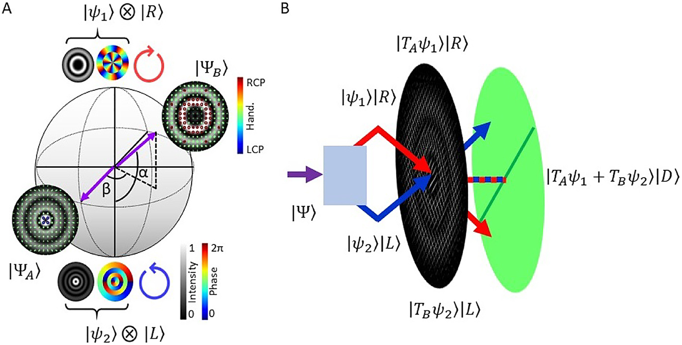
Concept diagrams illustrating our characterization scheme.
(A) HOPS with
We can then reconstruct |ψ1,2⟩ according to
this procedure is known as modal decomposition [33].
With |ψ1(2)⟩ specified, we can now determine α and β. To begin, let us consider taking inner products of |Ψ⟩ with |ψ1(2)⟩|D⟩ individually (i.e., we project into the spatial mode and polarization degree of freedom simultaneously) – where we denote the intensities of these projections as I1(2)
Next, we can consider taking inner products with respect to superpositions of spatial modes |ψ1(2)⟩
Using these six intensity measurements I i , we can construct the Cartesian coordinates Σ i of the state vector |Ψ⟩
Therefore, we can extract α and β as
A detailed derivation of the expression above is included in the Supplementary Information. The projection into the |D⟩ polarization allows for the exploitation of the third Arago–Fresnel law which states “Orthogonally polarized light derived from polarized light, when brought into the same plane, will interfere” [34]. From Eqs. (14) and (15) we can see how only six intensity measurements are required to extract global parameters α and β. Additionally, by simply replacing the spatial mode projections with identity projections, we recover spatially varying Stokes intensity measurements.
3 Experimental procedure
3.1 Generation
In order to test our detection scheme on a variety of vector beams we implemented a generation process which used the arrangement shown in (the left of) Figure 2 [17]. A Gaussian beam from a 632.8 nm HeNe laser was expanded and collimated using lenses EL and CL respectively – such that the central region approximated a constant intensity plane wave. A half-wave plate (HWP) was used to change the plane of polarization to diagonal. The expanded beam was passed through a WP (splitting the horizontally and vertically polarized components at an angle of
Here,

(Left) Diagram showing the arrangement used to generate arbitrary vector beams using a Wollaston prism to separate orthogonal circular polarizations and a DMD to recombine these – post modulation. (Right) Diagram showing the arrangement used to characterize arbitrary vector fields making use of a Wollaston prism to separate and a DMD to recombine orthogonal polarization components, with a linear polarizer to allow for interference of orthogonally polarized components. Abbreviations: HeNe – helium neon laser, EL – expansion lens, CL – collimation lens, HWP – half-wave plate, WP – Wollaston prism, BS – beam splitter, LP – linear polarizer, DMD – digital micro-mirror device, FL – Fourier lens, IFL – inverse Fourier lens, CCD – charge coupled device.
3.2 Detection
The core device – the detection system (shown on the right of Figure 2), was arranged with a QWP placed before a WP positioned at the plane of interest, which – together – separated the right- and left-circularly polarized components of the input field at an angle of 1°. A 4f imaging system was used to image this plane onto the screen of a DMD (TI-DLP4710). A diagonally orientated linear polarizer (LP) was placed within the 4f system in order to acquire projections of orthogonal polarizations in the same plane. The detection DMD was also addressed with multiplexed complex amplitude holograms of the form in Eq. (16). The Fourier intensity of the modulated combined beam at the DMD was imaged onto a CCD1 using a Fourier lens (FL), measuring on-axis intensities at this plane together with appropriate TA(B) allowed for determination of inner products [33]. A 50:50 beam splitter (BS) was used to capture the image plane intensity using a second CCD2 after an aperture (A) and an inverse Fourier lens (IFL). In Table 1 we show the transmission functions TA(B) used to acquire
where s i = ∫S i (r)dr are the global Stokes parameters, with S i being the spatially varying Stokes parameters determined as
Table showing the transmission functions TA(B) used to acquire measurements to specify: orthogonal circularly polarized components of a vector field (top), the relative amplitudes and phases of the orthogonal components (middle) and the Stokes intensity measurements (bottom).
| TA | TB | CCD | Component | Measurement |
|---|---|---|---|---|
|
|
0 | 1 | | ψ 1 ⟩ |
|
| 0 |
|
1 | |ψ 2 ⟩ |
|
|
|
0 | 1 | | ψ 1 ⟩ |
|
| 0 |
|
1 | | ψ 2 ⟩ |
|
|
|
0 | 1 | | ψ 1 ⟩ |
|
| 0 |
|
1 | | ψ 2 ⟩ |
|
|
|
0 | 1 | | ψ 1 ⟩ | I 1 |
| 0 |
|
1 | | ψ 2 ⟩ | I 2 |
|
|
|
1 | | ψ 1 ⟩ & | ψ 2 ⟩ | I 3 |
|
|
|
1 | | ψ 1 ⟩ & | ψ 2 ⟩ | I 4 |
|
|
|
1 | | ψ 1 ⟩ & | ψ 2 ⟩ | I 5 |
|
|
|
1 | | ψ 1 ⟩ & | ψ 2 ⟩ | I 6 |
| 1 | 0 | 2 | | ψ 1 ⟩ | I R |
| 0 | 1 | 2 | | ψ 2 ⟩ | I L |
| 1 | 1 | 2 | | ψ 1 ⟩ & | ψ 2 ⟩ | I H |
| 1 | e iπ/2 | 2 | | ψ 1 ⟩ & | ψ 2 ⟩ | I D |
4 Results
As an initial demonstration of arbitrary vector state measurements, we generated cylindrical vector vortex beams (i.e.,
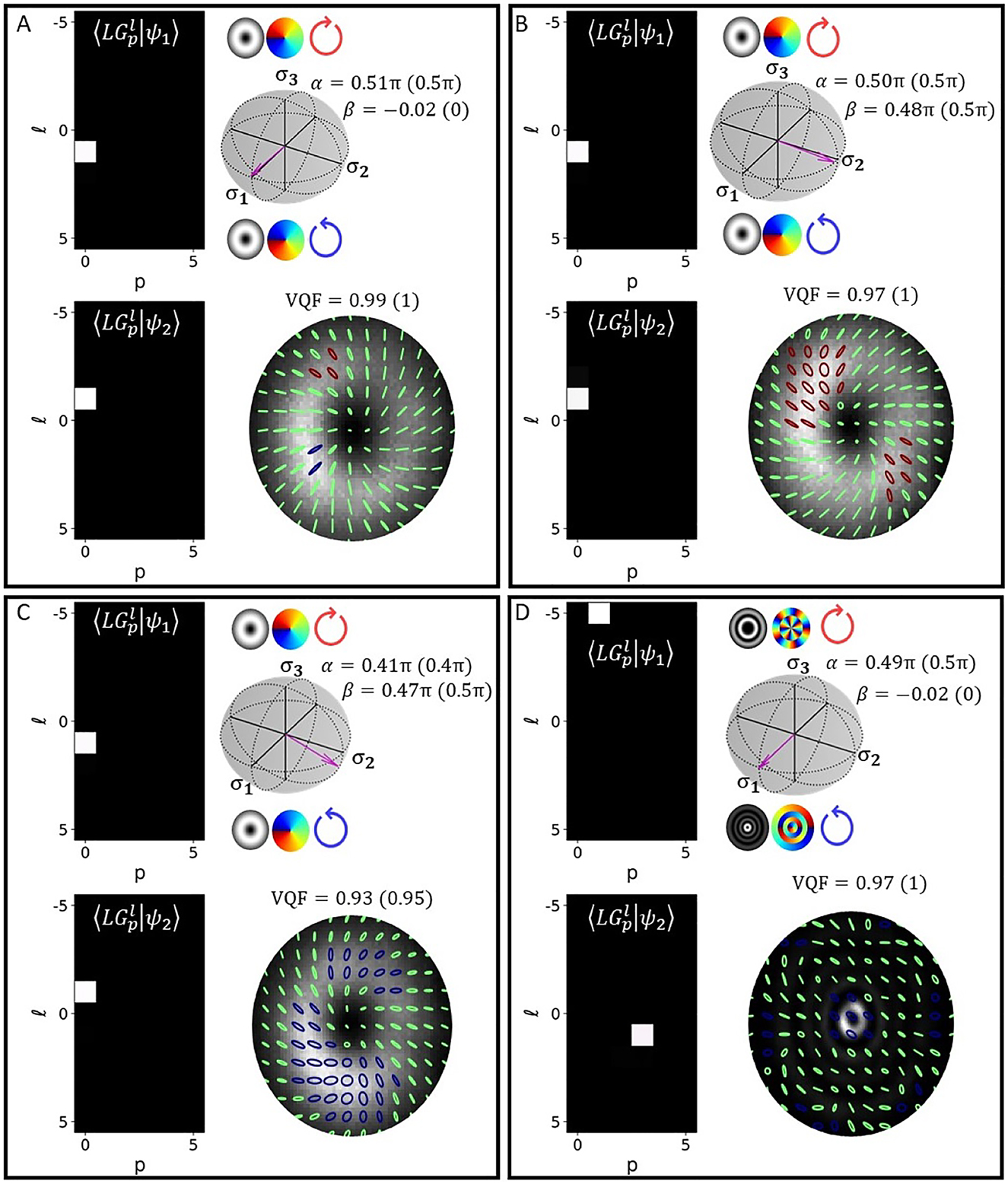
Crosstalk matrices (left), HOPS spheres with associated state vectors (top right) and SOP (bottom right) – measured for beams generated with (A) α = β = 0,
In Figure 4 we present results, displaying our technique’s performance in characterizing vector beams made up of orthogonally polarized components with fractional OAM. The beams were generated by encoding TA(B) = e±iφM on the generation DMD, where φ is the azimuthal coordinate and M = m + μ is a fractional OAM index, with
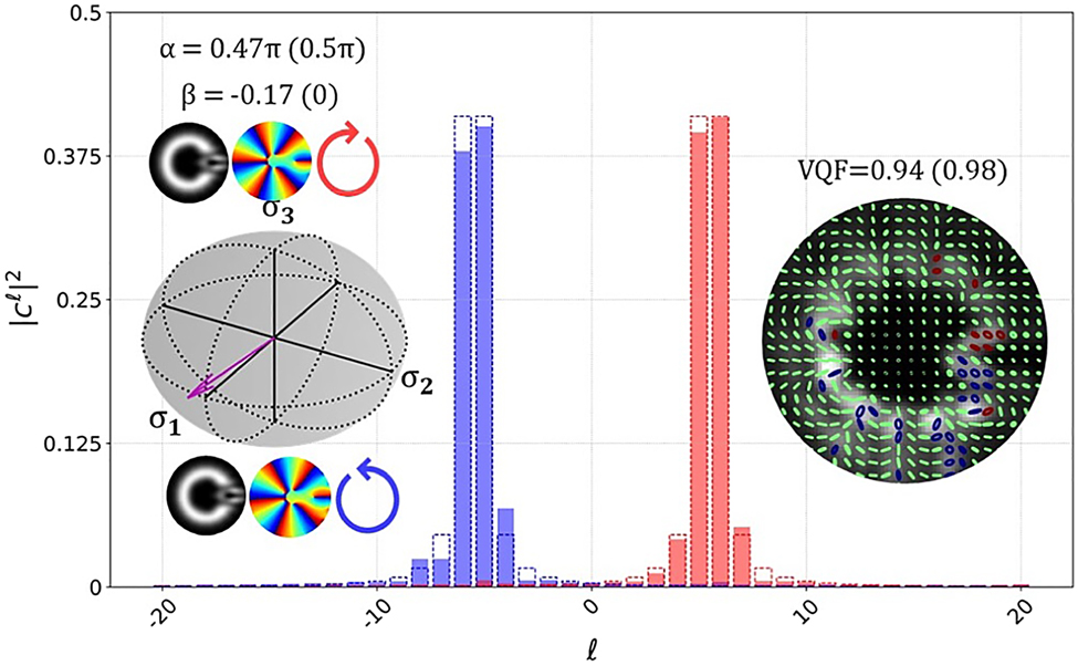
OAM spectra for individual components |ψ1(2)⟩ = e±i5.5φ (red – |ψ1⟩, blue – |ψ2⟩; experimental results in solid bars and theoretical prediction in dashed lines). The vector on the HOPS sphere and SOP for the vector beam generated by the orthogonal fractional OAM components are included as insets.
It should be noted that factors of the above expression relating the orientation of the phase discontinuity to the intra-modal phases have been omitted for brevity. We also adjusted our detection scheme to that of a phase only OAM decomposition, this avoids the need to sample the variety of radial orders which naturally manifest from phase plates (interested readers are directed to Refs [39, 41]). The OAM decomposition involves setting transmission functions equal to e−ilφ, since these are not eigenmodes of free space the physical effect is measuring the total power of
In Figure 5 we can see results obtained for beams with l = ±40. This represents the largest mode order our system is able to analyse (with a beam waist of w0 = 0.6 mm). This limitation of the system is determined by the size of the DMD and/or WP which impedes detection of beams with a larger spatial extent, this limit will generally precede the mode fidelity limit of the DMD which has been shown to exceed that of SLMs [42]. The crosstalk matrices presented, represent a portion of the entire l ∈ [−50, 50], p ∈ [0, 10] subspace which was sampled. The power in the desired
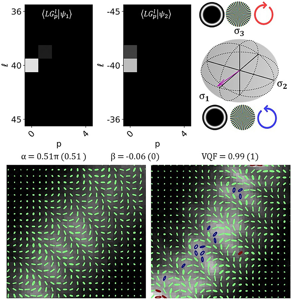
Crosstalk matrices and state vector lying on the HOPS sphere for
5 Conclusions
We have presented our arrangement, composed of a WP to separate orthogonal polarization components, a DMD to modulate and recombine them as well as a static linear polarizer to project the orthogonally polarized components into the same plane and interfere. We have demonstrated the effectiveness of our approach in completely specifying the state of a vector field, as well as in reconstructing the SOP of the field along with the associated VQF. We have shown how we can accurately characterise cylindrical vector vortex beams, vector beams with radial orders and vector beams with orthogonal components containing fractional OAM while also being able to extract digital Stokes intensity measurements. Additionally our system is able to characterize a significantly large subset of mode orders while maintaining a more compact arrangement while avoiding the need for reference fields, therefore addressing some of the problems faced by preceding vectorial characterization techniques. Furthermore the dynamic nature of the arrangement as well as the dual Fourier and image plane sampling leaves room for extensions to the functionality of our scheme. We believe this scheme will be of interest in industry, particularly for the characterization of liquid crystal and metasurface q-plates and j-plates, as well as other areas such as communications, microscopy and laser machining – where vectorial structured light is seeing increasing interest.
Acknowledgments
The authors thank Prof. Andrew Forbes, for many valuable discussions. KS acknowledges funding from the Department of Science and Innovation (South Africa) as well as the Council for Scientific and Industrial Research (South Africa).
-
Author contribution: All the authors have accepted responsibility for the entire content of this submitted manuscript and approved submission.
-
Research funding: None declared.
-
Conflict of interest statement: The authors declare no conflicts of interest regarding this article.
References
[1] A. Forbes, M. de Oliveira, and M. R. Dennis, “Structured light,” Nat. Photonics, vol. 15, no. 4, pp. 253–262, 2021. https://doi.org/10.1038/s41566-021-00780-4.Suche in Google Scholar
[2] H. Rubinsztein-Dunlop, A. Forbes, M. V. Berry, et al.., “Roadmap on structured light,” J. Opt., vol. 19, no. 1, p. 013001, 2016. https://doi.org/10.1088/2040-8978/19/1/013001.Suche in Google Scholar
[3] C. Rosales-Guzmán, B. Ndagano, and A. Forbes, “A review of complex vector light fields and their applications,” J. Opt., vol. 20, no. 12, p. 123001, 2018. https://doi.org/10.1088/2040-8986/aaeb7d.Suche in Google Scholar
[4] H. Larocque, D. Sugic, D. Mortimer, et al.., “Reconstructing the topology of optical polarization knots,” Nat. Phys., vol. 14, no. 11, pp. 1079–1082, 2018. https://doi.org/10.1038/s41567-018-0229-2.Suche in Google Scholar
[5] T. Bauer, P. Banzer, E. Karimi, et al.., “Observation of optical polarization möobius strips,” Science, vol. 347, no. 6225, pp. 964–966, 2015. https://doi.org/10.1126/science.1260635.Suche in Google Scholar PubMed
[6] K. Singh, W. T. Buono, A. Forbes, and A. Dudley, “Accelerating polarization structures in vectorial fields,” Opt. Express, vol. 29, no. 2, pp. 2727–2737, 2021. https://doi.org/10.1364/oe.411029.Suche in Google Scholar
[7] R. Rajput and P. Senthilkumaran, “Optical currents in poincaré beams,” Phys. Rev. A, vol. 102, no. 1, p. 013509, 2020.10.1103/PhysRevA.102.013509Suche in Google Scholar
[8] G. Milione, T. A. Nguyen, J. Leach, D. A. Nolan, and R. R. Alfano, “Using the nonseparability of vector beams to encode information for optical communication,” Opt. Lett., vol. 40, no. 21, pp. 4887–4890, 2015. https://doi.org/10.1364/ol.40.004887.Suche in Google Scholar
[9] S. Berg-Johansen, F. Töppel, B. Stiller, et al.., “Classically entangled optical beams for high-speed kinematic sensing,” Optica, vol. 2, no. 10, pp. 864–868, 2015. https://doi.org/10.1364/optica.2.000864.Suche in Google Scholar
[10] G. Bautista and M. Kauranen, “Vector-field nonlinear microscopy of nanostructures,” ACS Photonics, vol. 3, no. 8, pp. 1351–1370, 2016. https://doi.org/10.1021/acsphotonics.6b00052.Suche in Google Scholar
[11] S. Matsusaka, Y. Kozawa, and S. Sato, “Micro-hole drilling by tightly focused vector beams,” Opt. Lett., vol. 43, no. 7, pp. 1542–1545, 2018. https://doi.org/10.1364/ol.43.001542.Suche in Google Scholar PubMed
[12] D. G. Hall, “Vector-beam solutions of Maxwell’s wave equation,” Opt. Lett., vol. 21, no. 1, pp. 9–11, 1996. https://doi.org/10.1364/ol.21.000009.Suche in Google Scholar PubMed
[13] H. Sroor, Y.-W. Huang, B. Sephton, et al.., “High-purity orbital angular momentum states from a visible metasurface laser,” Nat. Photonics, vol. 14, no. 8, pp. 498–503, 2020. https://doi.org/10.1038/s41566-020-0623-z.Suche in Google Scholar
[14] A. H. Dorrah, N. A. Rubin, A. Zaidi, M. Tamagnone, and F. Capasso, “Metasurface optics for on-demand polarization transformations along the optical path,” Nat. Photonics, vol. 15, no. 4, pp. 287–296, 2021. https://doi.org/10.1038/s41566-020-00750-2.Suche in Google Scholar
[15] A. Rubano, F. Cardano, B. Piccirillo, and L. Marrucci “Q-plate technology: a progress review,” JOSA B, vol. 36, no. 5, pp. D70–D87, 2019. https://doi.org/10.1364/josab.36.000d70.Suche in Google Scholar
[16] C. Rosales-Guzmán, N. Bhebhe, and A. Forbes, “Simultaneous generation of multiple vector beams on a single slm,” Opt. Express, vol. 25, no. 21, pp. 25697–25706, 2017. https://doi.org/10.1364/oe.25.025697.Suche in Google Scholar PubMed
[17] C. Rosales-Guzmán, X.-B. Hu, A. Selyem, et al.., “Polarisation-insensitive generation of complex vector modes from a digital micromirror device,” Sci. Rep., vol. 10, no. 1, pp. 1–9, 2020. https://doi.org/10.1038/s41598-020-66799-9.Suche in Google Scholar PubMed PubMed Central
[18] A. Selyem, C. Rosales-Guzmán, S. Croke, A. Forbes, and S. Franke-Arnold, “Basis-independent tomography and nonseparability witnesses of pure complex vectorial light fields by Stokes projections,” Phys. Rev. A, vol. 100, no. 6, p. 063842, 2019. https://doi.org/10.1103/physreva.100.063842.Suche in Google Scholar
[19] B. Ndagano, H. Sroor, M. McLaren, C. Rosales-Guzmán, and A. Forbes, “Beam quality measure for vector beams,” Opt. Lett., vol. 41, no. 15, pp. 3407–3410, 2016. https://doi.org/10.1364/ol.41.003407.Suche in Google Scholar
[20] B. Ndagano, B. Perez-Garcia, F. S. Roux, et al.., “Characterizing quantum channels with non-separable states of classical light,” Nat. Phys., vol. 13, no. 4, pp. 397–402, 2017. https://doi.org/10.1038/nphys4003.Suche in Google Scholar
[21] B. Ndagano, I. Nape, B. Perez-Garcia, et al.., “A deterministic detector for vector vortex states,” Sci. Rep., vol. 7, no. 1, pp. 1–8, 2017. https://doi.org/10.1038/s41598-017-12739-z.Suche in Google Scholar PubMed PubMed Central
[22] I. Moreno, J. A. Davis, K. Badham, M. M. Sánchez-López, J. E. Holland, and D. M. Cottrell, “Vector beam polarization state spectrum analyzer,” Sci. Rep., vol. 7, no. 1, pp. 1–10, 2017. https://doi.org/10.1038/s41598-017-02328-5.Suche in Google Scholar PubMed PubMed Central
[23] B. Zhao, X.-B. Hu, V. Rodríguez-Fajardo, et al.., “Determining the non-separability of vector modes with digital micromirror devices,” Appl. Phys. Lett., vol. 116, no. 9, p. 091101, 2020. https://doi.org/10.1063/1.5142163.Suche in Google Scholar
[24] C. He, J. Lin, J. Chang, et al.., “Full Poincaré mapping for ultra-sensitive polarimetry,” arXiv preprint arXiv:2101.09372, 2021.Suche in Google Scholar
[25] C. He and M. J. Booth, “Full poincaré polarimetry for enhanced microscopic sensing,” in Novel Techniques in Microscopy, Washington, DC, Optical Society of America, 2021, p. NM1C-2.10.1364/NTM.2021.NM1C.2Suche in Google Scholar
[26] Q. Hu, C. He, and M. J. Booth, “Arbitrary complex retarders using a sequence of spatial light modulators as the basis for adaptive polarisation compensation,” J. Opt., vol. 23, no. 6, p. 065602, 2021. https://doi.org/10.1088/2040-8986/abed33.Suche in Google Scholar
[27] C. He, Q. Hu, Y. Dai, and M. J. Booth, “Vectorial adaptive optics-correction of polarization and phase,” in Adaptive Optics: Analysis, Methods & Systems, Washington, DC, Optical Society of America, 2020, p. OF2B-5.10.1364/AOMS.2020.OF2B.5Suche in Google Scholar
[28] K. Singh, N. Tabebordbar, A. Forbes, and A. Dudley, “Digital Stokes polarimetry and its application to structured light: tutorial,” JOSA A, vol. 37, no. 11, pp. C33–C44, 2020. https://doi.org/10.1364/josaa.397912.Suche in Google Scholar PubMed
[29] S. Liu, L. Han, P. Li, Y. Zhang, H. Cheng, and J. Zhao, “A method for simultaneously measuring polarization and phase of arbitrarily polarized beams based on pancharatnam-berry phase,” Appl. Phys. Lett., vol. 110, no. 17, p. 171112, 2017. https://doi.org/10.1063/1.4982650.Suche in Google Scholar
[30] S. Qi, S. Liu, L. Han, et al.., “Dynamically measuring the holo-information of light fields in three-dimensional space using a periodic polarization-structured light,” Sci. China Phys. Mech., vol. 64, no. 6, pp. 1–8, 2021. https://doi.org/10.1007/s11433-021-1686-9.Suche in Google Scholar
[31] B. Ge, R. Zhou, Y. Takiguchi, Z. Yaqoob, and P. T. So, “Single-shot optical anisotropy imaging with quantitative polarization interference microscopy,” Laser Photon. Rev., vol. 12, no. 8, p. 1800070, 2018. https://doi.org/10.1002/lpor.201800070.Suche in Google Scholar PubMed PubMed Central
[32] X. Yi, Y. Liu, X. Ling, et al.., “Hybrid-order poincaré sphere,” Phys. Rev. A, vol. 91, no. 2, p. 023801, 2015. https://doi.org/10.1103/physreva.91.023801.Suche in Google Scholar
[33] C. Schulze, D. Naidoo, D. Flamm, O. A. Schmidt, A. Forbes, and M. Duparré, “Wavefront reconstruction by modal decomposition,” Opt. Express, vol. 20, no. 18, pp. 19714–19725, 2012. https://doi.org/10.1364/oe.20.019714.Suche in Google Scholar PubMed
[34] R. Barakat, “Analytic proofs of the arago–fresnel laws for the interference of polarized light,” JOSA A, vol. 10, no. 1, pp. 180–185, 1993. https://doi.org/10.1364/josaa.10.000180.Suche in Google Scholar
[35] W.-H. Lee, “Binary computer-generated holograms,” Appl. Opt., vol. 18, no. 21, pp. 3661–3669, 1979. https://doi.org/10.1364/ao.18.003661.Suche in Google Scholar PubMed
[36] S. Scholes, R. Kara, J. Pinnell, V. Rodríguez-Fajardo, and A. Forbes, “Structured light with digital micromirror devices: a guide to best practice,” Opt. Eng., vol. 59, no. 4, p. 041202, 2019. https://doi.org/10.1117/1.oe.59.4.041202.Suche in Google Scholar
[37] A. Manthalkar, I. Nape, N. T. Bordbar, et al.., “All-digital Stokes polarimetry with a digital micromirror device,” Opt. Lett., vol. 45, no. 8, pp. 2319–2322, 2020. https://doi.org/10.1364/ol.389346.Suche in Google Scholar
[38] J. B. Götte, S. Franke-Arnold, R. Zambrini, and S. M. Barnett, “Quantum formulation of fractional orbital angular momentum,” J. Mod. Opt., vol. 54, no. 12, pp. 1723–1738, 2007. https://doi.org/10.1080/09500340601156827.Suche in Google Scholar
[39] J. B. Götte, K. O’Holleran, D. Preece, et al.., “Light beams with fractional orbital angular momentum and their vortex structure,” Opt. Express, vol. 16, no. 2, pp. 993–1006, 2008. https://doi.org/10.1364/oe.16.000993.Suche in Google Scholar PubMed
[40] B. Sephton, Y.-W. Huang, A. Ambrosio, et al.., “Purity and efficiency of hybrid orbital angular momentum-generating metasurfaces,” J. Nanophotonics, vol. 14, no. 1, p. 016005, 2020. https://doi.org/10.1117/1.jnp.14.016005.Suche in Google Scholar
[41] B. Sephton, A. Dudley, and A. Forbes, “Revealing the radial modes in vortex beams,” Appl. Opt., vol. 55, no. 28, pp. 7830–7835, 2016. https://doi.org/10.1364/ao.55.007830.Suche in Google Scholar
[42] S. Turtaev, I. T. Leite, K. J. Mitchell, M. J. Padgett, D. B. Phillips, and T. Čižmár, “Comparison of nematic liquid-crystal and dmd based spatial light modulation in complex photonics,” Opt. Express, vol. 25, no. 24, pp. 29874–29884, 2017. https://doi.org/10.1364/OE.25.029874.Suche in Google Scholar PubMed
Supplementary Material
The online version of this article offers supplementary material (https://doi.org/10.1515/nanoph-2021-0484).
© 2021 Keshaan Singh et al., published by De Gruyter, Berlin/Boston
This work is licensed under the Creative Commons Attribution 4.0 International License.
Artikel in diesem Heft
- Frontmatter
- Editorial
- Photonic angular momentum: progress and perspectives
- Reviews
- Spiraling light: from donut modes to a Magnus effect analogy
- Orbital angular momentum and beyond in free-space optical communications
- Research Articles
- Parabolic-accelerating vector waves
- Experimental synthesis of partially coherent beam with controllable twist phase and measuring its orbital angular momentum
- Harnessing of inhomogeneously polarized Hermite–Gaussian vector beams to manage the 3D spin angular momentum density distribution
- Introducing Berry phase gradients along the optical path via propagation-dependent polarization transformations
- Angular momentum redirection phase of vector beams in a non-planar geometry
- Transverse shifts and time delays of spatiotemporal vortex pulses reflected and refracted at a planar interface
- Spatiotemporal optical vortices with arbitrary orbital angular momentum orientation by astigmatic mode converters
- Digital toolbox for vector field characterization
- Phase conjugation of twisted Gaussian Schell model beams in stimulated down-conversion
- Spin to orbital angular momentum transfer in frequency up-conversion
- Deep-learning-based recognition of multi-singularity structured light
- Reconfigurable terahertz metasurfaces coherently controlled by wavelength-scale-structured light
- Nonlinear wavefront engineering with metasurface decorated quartz crystal
- Nanostructured silica spin–orbit optics for modal vortex beam shaping
- Spin separation based on-chip optical polarimeter via inverse design
- Photonic integrated chip enabling orbital angular momentum multiplexing for quantum communication
- Fabrication of lithium niobate fork grating by laser-writing-induced selective chemical etching
- High-power thin-disk lasers emitting beams with axially-symmetric polarizations
- The generation of femtosecond optical vortex beams with megawatt powers directly from a fiber based Mamyshev oscillator
- Generation of hexagonal close-packed ring-shaped structures using an optical vortex
- A phase-to-intensity strategy of angular velocity measurement based on photonic orbital angular momentum
- SDM transmission of orbital angular momentum mode channels over a multi-ring-core fibre
- Dynamic aerosol and dynamic air-water interface curvature effects on a 2-Gbit/s free-space optical link using orbital-angular-momentum multiplexing